14 Amazon DevOps Engineer Interview Questions & Answers

amazon icon

Questions with Detailed ExplanationsWith Detailed Explanations

(Last Updated: September 1, 2026)

1. What happens from an S3 PUT request until the object is durably acknowledged?Cloud InfrastructureEasyAmazon

Question Details

Trace one successful object upload from the client request through endpoint resolution, authentication and authorization, request routing, integrity checks, storage across failure domains, and the response returned to the client. Also state how retries and duplicate requests are handled and what the durability acknowledgement does and does not guarantee about later reads.

Short Interview Answer (30-60 seconds)

At a high level, the goal is to accept an S3 PUT and return success only after the object is durably stored. The main challenge is validating the request, protecting the data across failure domains, and handling uncertain retries correctly. I would explain three parts: validate and route the request, store the object durably, then acknowledge success. If a response is lost, the client can retry, but another successful PUT may occur.

Detailed Explanation

The goal is to follow one successful object upload from the client until S3 says it succeeded. S3 must first check that the request is valid and allowed. It must then protect the object against the storage failures it is designed to handle before returning success. A lost response also creates uncertainty because the client may send the same PUT again. The diagram organizes the explanation into request entry and validation, internal storage and durability completion, then the response and retry behavior.

Useful Questions to Ask the Interviewer
  1. Should I assume a normal single-Region S3 PUT over HTTPS?
  2. Should I cover both normal PUT retries and multipart uploads?
  3. Should I explain what the success response means for later GET, HEAD, and LIST operations?
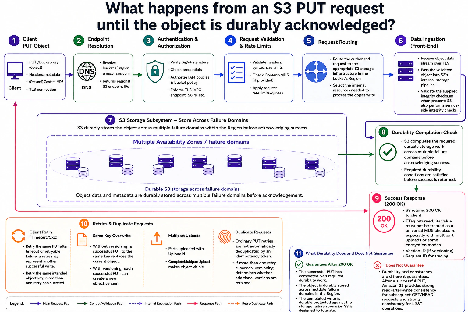
What happens from an S3 PUT request until the object is durably acknowledged? diagram
How to Explain It in an Interview
1. Start with the client and endpoint resolution

I would start with the request entering S3. The client sends a PUT for a bucket and object key over TLS. The request contains headers, metadata, and the object body. It may also include an integrity checksum such as Content-MD5.

Endpoint Resolution resolves the regional S3 endpoint. The request then reaches the S3 front-end through the protected network connection.

2. Authenticate, authorize, and validate the request

Next, S3 checks who sent the request and whether it is allowed. Authentication & Authorization verifies the SigV4 signature and credentials. It also checks IAM policies, the bucket policy, and the access conditions shown in the diagram.

Request Validation & Rate Limits checks headers, syntax, size limits, and an optional Content-MD5 value. Request limits and quotas can also be applied here. If these checks fail, the successful write path stops.

3. Route and ingest the object

After validation, Request Routing sends the authorized request to the appropriate S3 storage infrastructure in the bucket's Region. S3 selects the internal resources needed to process the object write.

Data Ingestion receives the object data over TLS. The validated object then enters S3's internal storage pipeline. If the client supplied an integrity checksum, S3 validates it. The diagram also shows service-side integrity checks during this stage.

4. Store the object and complete durability work

The S3 Storage Subsystem stores the object data and metadata across multiple Availability Zones or other failure domains in the Region. The diagram does not depend on a specific replica count or a documented internal replication algorithm.

The Durability Completion Check represents the point where S3 has completed its required durable storage work. The required durability conditions must be satisfied before success is returned. S3 then sends a 200 OK response to the client. The response includes an ETag and may include a Version ID when versioning is enabled. The ETag should not be treated as a universal MD5 checksum.

5. Explain retries, duplicates, and later reads

If the client times out or does not receive the response, it can retry the same intended object key. The first PUT may already have succeeded, so another retry may also become a successful write. Ordinary PUT retries are not automatically deduplicated by an idempotency token.

Without versioning, a successful PUT to the same key replaces the current object. With versioning, each successful PUT can create another object version. Multipart uploads use an UploadId, and CompleteMultipartUpload makes the completed object visible.

Durability and read consistency are separate guarantees. After a successful PUT, S3 provides strong read-after-write consistency for later GET and HEAD requests, and strong consistency for LIST operations.

Practical Complexity & Trade-offs

The benefit is that S3 waits for its required durability work before returning success. This protects a completed write across multiple failure domains in the Region. The downside appears when the client loses the response. The client may retry even though the first PUT already succeeded. Ordinary PUT retries are not automatically deduplicated. Without versioning, another successful PUT to the same key replaces the current object. With versioning, another successful PUT can create another version. We accept this because a timeout does not prove that the original write failed.

Why Interviewers Ask This

Interviewers ask this to see whether you can trace a cloud write from request entry to durable storage. They want to test your understanding of authentication, authorization, validation, integrity checks, failure domains, and acknowledgement timing. They also want to see whether you handle retry uncertainty correctly and understand that durability and read consistency answer different questions.
Interviewer may ask next
What changes if the client times out after sending the PUT and cannot tell whether S3 already stored the object?

I would retry the same intended object key, but I would not assume the retry is automatically deduplicated. A timeout only means the client did not receive the final response. The original PUT may still have completed successfully.

The affected part of the diagram is the Retries & Duplicate Requests section. Another successful PUT can happen when the client retries. Without bucket versioning, a successful PUT to the same key replaces the current object. With versioning enabled, another successful PUT can create another object version.

The retry still follows the normal validation, routing, integrity, storage, and durability-completion path. S3 only returns success after that request satisfies the required durability conditions.

The main downside is uncertainty after a lost response. The client cannot treat a timeout as proof that nothing was stored. Applications that care about repeated writes must design around that behavior.

What does the 200 OK durability acknowledgement guarantee about reading the object immediately afterward?

I would separate durability from read consistency because they answer different questions. The 200 OK means the successful PUT has completed S3's required durability work across multiple failure domains in the Region. It tells the client that the write reached the Durability Completion Check shown in the diagram.

For later reads, the diagram states that Amazon S3 provides strong read-after-write consistency after a successful PUT. A later GET or HEAD can therefore observe the completed write. LIST operations are also strongly consistent.

This does not change the request path. Authentication, authorization, validation, routing, integrity checks, durable storage, and the success response still happen in the same order.

The main interview point is that durability and consistency should not be mixed together. Durability describes whether stored data survives supported storage failures. Consistency describes what later reads observe.

2. How would you reach a database in a private subnet without using NAT or a bastion host?Cloud InfrastructureMediumAmazon

Question Details

Design an administrative or application access path to a database that has no public route and must remain private. Cover the initiating principal, private network path, DNS resolution, database authentication, authorization, encryption, audit evidence, and how you prove that neither the client nor the database traverses the public internet.

Short Interview Answer (30-60 seconds)

At a high level, I would keep both the administrator and the database off the public internet. The main challenge is creating a private access path while keeping strong identity, authorization, encryption, and audit controls. I would explain it in three parts: private connectivity, Session Manager port forwarding, and database security. The administrator enters through Direct Connect or VPN, uses private Systems Manager endpoints, and reaches RDS through an SSM-managed node. The downside is extra private-network and endpoint setup.

Detailed Explanation

The goal is to let an administrator reach a private database without exposing either side to the public internet. The hard part is providing useful administrative access without a bastion host or NAT gateway. The diagram solves this with private corporate connectivity, AWS Systems Manager Session Manager, and an SSM-managed node inside the VPC. Identity rules decide who may start a session. Private DNS finds internal addresses. Encryption protects each network leg. Logs provide evidence that the access path stays private.

Useful Questions to Ask the Interviewer
  1. Does the administrator already have Direct Connect or Site-to-Site VPN connectivity?
  2. Can we use an SSM-managed EC2 instance as the private connection point?
  3. Should the database use IAM database authentication or database credentials stored in Secrets Manager?
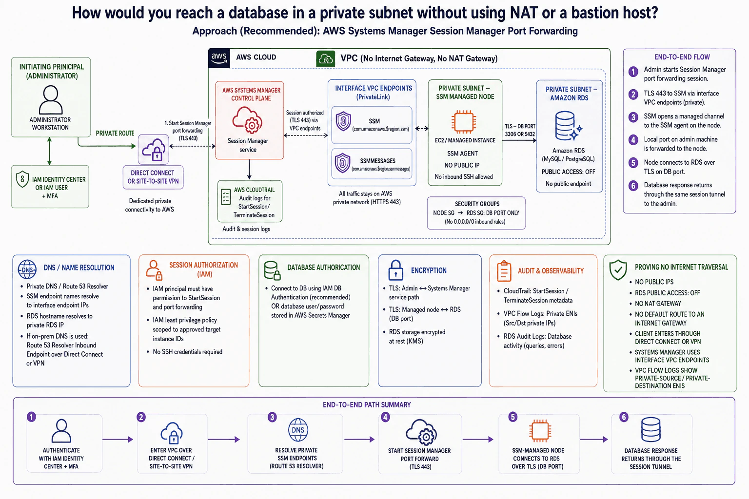
How would you reach a database in a private subnet without using NAT or a bastion host? diagram
How to Explain It in an Interview
1. Start with identity and private connectivity

I would first authenticate the administrator with IAM Identity Center or an IAM user and require MFA. Then I would give the workstation a private network path into AWS using Direct Connect or Site-to-Site VPN.

This means the client does not need a public route into the VPC. The design does not depend on a bastion host, a public EC2 address, or a NAT gateway.

2. Reach Systems Manager through private VPC endpoints

Next, I would use AWS Systems Manager Session Manager for the administrative connection. The VPC has interface VPC endpoints for SSM and SSMMESSAGES.

These endpoints have private IP addresses inside the VPC. Systems Manager traffic uses HTTPS on port 443 through those private endpoints. The SSM-managed node also keeps its Systems Manager channel through those endpoints, so it does not need internet access.

IAM provides session authorization. The administrator gets only the StartSession permission needed for approved managed-node instance IDs. The managed node does not accept inbound SSH.

3. Port-forward the database connection

The administrator starts a Session Manager port-forwarding session. A local port on the workstation is carried through the Session Manager tunnel.

The SSM-managed node then opens the database connection to Amazon RDS. It uses the required database port, such as 3306 or 5432, over TLS. The node security group can reach the RDS security group only on that database port.

RDS remains in a private subnet. Public access is turned off. There is no broad 0.0.0.0/0 database ingress rule.

4. Resolve names and authenticate to RDS

Private DNS keeps name resolution on the private path. SSM endpoint names resolve to interface endpoint private IPs. The RDS hostname resolves to the private RDS address.

If DNS starts on-premises, Route 53 Resolver can provide private name resolution across Direct Connect or VPN.

Session authorization and database authentication are separate. RDS can use IAM database authentication or database credentials stored in Secrets Manager. RDS storage is encrypted at rest.

5. Prove that the path never used the internet

Finally, I would prove the design with configuration and logs. CloudTrail records Session Manager actions such as StartSession and TerminateSession. VPC Flow Logs show traffic between private network interfaces. RDS audit logs show database activity.

The network evidence is also clear. There are no public IPs, no NAT gateway, and no default route to an Internet Gateway. RDS public access is off. Systems Manager uses interface VPC endpoints. The database response returns through the same Session Manager tunnel.

Practical Complexity & Trade-offs

The benefit is that the database never needs a public address, and the administrator does not need a bastion host. Session Manager also removes inbound SSH access. Private VPC endpoints let the managed node use Systems Manager without NAT. The downside is more private-network setup. Direct Connect or VPN, Route 53 Resolver, VPC endpoints, IAM rules, and security groups must all be configured correctly. The SSM-managed node is also another component that must stay healthy and managed. We accept this extra work because it gives a controlled private path with clear identity, network, encryption, and audit evidence.

Why Interviewers Ask This

The interviewer wants to see whether you understand private cloud access as a complete security problem. They are checking whether you can separate identity, session authorization, database authentication, networking, DNS, encryption, and auditing. They also want to know whether you understand how Session Manager removes the need for SSH and bastion hosts. A strong answer proves the path is private instead of only claiming that it is private.

Interviewer may ask next
What would you change if the company did not already have Direct Connect or Site-to-Site VPN connectivity?

I would keep the private RDS, SSM-managed node, security groups, and Session Manager design the same. The part that must change is how the administrator reaches the private AWS network.

The diagram depends on Direct Connect or Site-to-Site VPN for the private client path. Without one of those connections, the workstation cannot follow the same private route into the VPC. I would first establish an approved private network connection before using this administrative workflow.

After that connection exists, the rest stays the same. IAM Identity Center and MFA authenticate the administrator. Session Manager still uses the SSM and SSMMESSAGES interface VPC endpoints. The managed node still reaches RDS over TLS on the database port. RDS still has public access turned off, and the managed node still needs no inbound SSH.

The main downside is extra networking work before administrators can use the design. That private connection also has its own operating cost and availability requirements.

How would you prove to an auditor that the database connection did not traverse the public internet?

I would prove it with both network configuration and logs. I would not rely only on saying that the architecture is private.

First, I would show that RDS has public access turned off and the SSM-managed node has no public IP. I would show that the relevant private route tables have no default route to an Internet Gateway or NAT gateway. I would also show that the administrator enters through Direct Connect or Site-to-Site VPN.

Next, I would show the SSM and SSMMESSAGES interface VPC endpoints. They explain how Systems Manager traffic uses private endpoint IPs instead of an internet path. Private DNS records should resolve the service and RDS names to private addresses.

For audit evidence, CloudTrail shows StartSession and TerminateSession activity. VPC Flow Logs show the private source and destination network interfaces. RDS audit logs show database activity.

The downside is that several evidence sources must be reviewed together. No single log proves the complete end-to-end path by itself.

3. What happens when cross-Region S3 replication races with a delete marker?Cloud InfrastructureHardAmazon

Question Details

Analyze an enabled-versioning source bucket and destination bucket when an object update and a delete marker are created close together while replication is delayed. Explain the possible ordering observed at the destination, how versions and delete markers are represented, what replication status proves, and how an application should recover without assuming that arrival order equals source-operation order.

Short Interview Answer (30-60 seconds)

At a high level, this is about delayed cross-Region replication changing what the destination may temporarily show. The main challenge is that a new object version and its delete marker can become visible there in a different order. I would explain the source operations, the two destination arrival orders, and safe recovery. Replication status describes each individual item, not ordering between items. The trade-off is that applications need version-aware logic instead of trusting arrival order.

Detailed Explanation

The same file is copied from one place to another. A new copy of the file is saved, and almost immediately the file is deleted. Because the copy work happens later, the second place may see the save and delete in a different order. That can make the file appear present or missing for a while. I would explain what is saved first, what the second place may see, what the copy status really tells us, and how the application can recover safely without guessing the original order.

Useful Questions to Ask the Interviewer
  1. Is delete marker replication enabled for this replication rule?
  2. Does the application need to know the exact business order of updates and deletes?
  3. Can the application store its own sequence or event ID with each change?
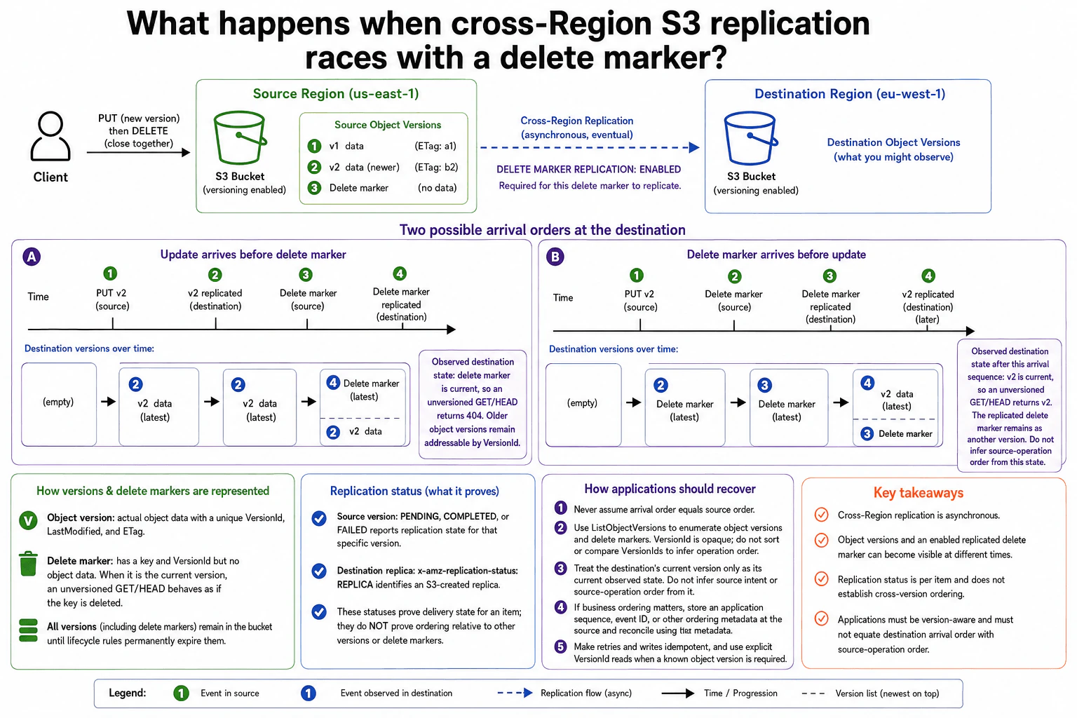
What happens when cross-Region S3 replication races with a delete marker? diagram
How to Explain It in an Interview
1. Start with the versioned source bucket

I would start with what happens in the Source Region. Versioning is enabled, so a PUT creates a new object version instead of removing the older version.

The diagram shows old data as v1 and newer data as v2. A DELETE then creates a delete marker. A delete marker has a key and VersionId, but it contains no object data.

Delete marker replication is enabled in this design. That setting is required for the delete marker shown in the diagram to be copied to the Destination Region.

2. Explain why destination arrival order can differ

Cross-Region Replication works asynchronously, which means the copy happens in the background. The application must not assume that destination arrival order proves source-operation order.

In path A, v2 reaches the destination before the delete marker. When the delete marker later becomes current, an unversioned GET or HEAD returns 404. Older object versions are still available when requested with their VersionId.

In path B, the delete marker reaches the destination before v2. When v2 arrives later, v2 becomes the destination's current observed version. An unversioned GET or HEAD then returns v2. The replicated delete marker still remains in the version history.

3. Explain how versions and delete markers are represented

I would next explain that S3 keeps these entries separately. An object version contains object data and metadata and has its own VersionId.

A delete marker has a key and VersionId but no object data. When it is current, an unversioned GET or HEAD behaves as if the key is deleted. Older versions remain until lifecycle rules permanently remove them.

4. Explain what replication status proves

Replication status is useful, but it only describes a specific item. On the source, PENDING, COMPLETED, or FAILED reports the replication state for that version.

On an S3-created destination replica, x-amz-replication-status: REPLICA identifies the object as a replica. These statuses tell us about delivery. They do not prove ordering between different object versions or delete markers.

5. Explain safe application recovery

The application should never rebuild source order from destination arrival order. It can use ListObjectVersions to enumerate object versions and delete markers.

VersionId values are opaque, so the application should not compare or sort them to infer operation order. The destination's current version represents only what the destination currently shows.

If business ordering matters, store an application sequence, event ID, or similar ordering value at the source. Use that value when deciding which operation should win. Make retries and writes idempotent, meaning repeating the same operation does not produce a wrong result. When a known object version is required, read that exact VersionId.

Practical Complexity & Trade-offs

The benefit is that S3 Versioning keeps object history, so an update or delete does not automatically destroy older versions. Cross-Region Replication also copies changes without blocking the source operation. The downside is that the destination can show those changes in a different order while replication is delayed. Replication status helps with one item at a time, but it does not establish order between versions. We accept this by making the application version-aware. If exact business order matters, the application stores its own sequence or event ID and uses that value to decide the correct result.

Why Interviewers Ask This

The interviewer wants to see whether you understand delayed, asynchronous replication instead of assuming copies arrive in source order. They also want to test your understanding of S3 versions, delete markers, and replication status. The key judgment is knowing which facts S3 proves and where the application needs its own ordering rule. A strong candidate can also explain safe recovery without inventing guarantees that S3 does not provide.

Interviewer may ask next
What would you change if the application must know the exact business order of every update and delete?

I would keep the same S3 buckets, Versioning, and Cross-Region Replication, but I would not use destination arrival order to decide business order. Each source operation would carry an application sequence, event ID, or another ordering value before replication starts.

When the destination sees v2 or a delete marker, the application can inspect that stored value. It can then decide which operation represents the newer business action. This stays correct whether the delete marker arrives first or v2 arrives first.

I would still use ListObjectVersions when I need to enumerate the available object versions and delete markers. I would not compare VersionIds because they are opaque and do not define operation order. When I need a known object version, I can request its explicit VersionId.

The downside is extra metadata and application logic. The application now owns the business-order rule instead of relying only on the destination's current observed state.

How would you handle a source version whose replication status stays PENDING or becomes FAILED?

I would treat the replication status as information about that specific source version. PENDING means replication for that version has not completed yet. FAILED means replication for that version failed and needs investigation.

I would not use either status to make claims about the order of other versions or delete markers. Another item may already be visible in the Destination Region. The application therefore still needs version-aware behavior and must not rebuild source order from the destination's current state.

If the workflow can safely retry an operation, I would make that retry idempotent, meaning repeating it cannot create an incorrect result. If business ordering matters, I would continue using the source-side application sequence or event ID. For a known object version, I would use its explicit VersionId when reading it.

The downside is that the application may need to wait or retry while replication catches up, and FAILED items require operational investigation.

4. What role does Docker play in a DevOps workflow, and how would you deploy an application with it?Containers And KubernetesEasyAmazon

Question Details

Describe the path from application source and a Dockerfile to a built image and a running container. Cover build context, layers, runtime configuration, ports, volumes, environment values, image storage, startup command, health verification, logs, and how the same image is promoted rather than rebuilt for each environment.

Short Interview Answer (30-60 seconds)

At a high level, Docker packages the application and its dependencies into one portable image. The main challenge is keeping that image consistent while changing runtime settings for each environment. I would explain the workflow in three parts: build the image, store and run it, then verify and promote it. We build from the source and Dockerfile, push the image to a registry, and run containers with ports, volumes, environment values, and a startup command. The same tested image is promoted instead of rebuilt.

Detailed Explanation

The goal is to package an application so it can run the same way in different environments. We start with the application files and instructions that describe how to package them. The difficult part is keeping the application package unchanged while still allowing each environment to use different runtime settings. The diagram solves this by separating image creation, image storage, container startup, verification, and promotion. This gives us one repeatable image that can move from development to staging and production without being rebuilt.

Useful Questions to Ask the Interviewer
  1. Where should the built container images be stored?
  2. Which runtime values should change between environments?
  3. Does the application need persistent data through a volume?
  4. What health check should prove the application is working?
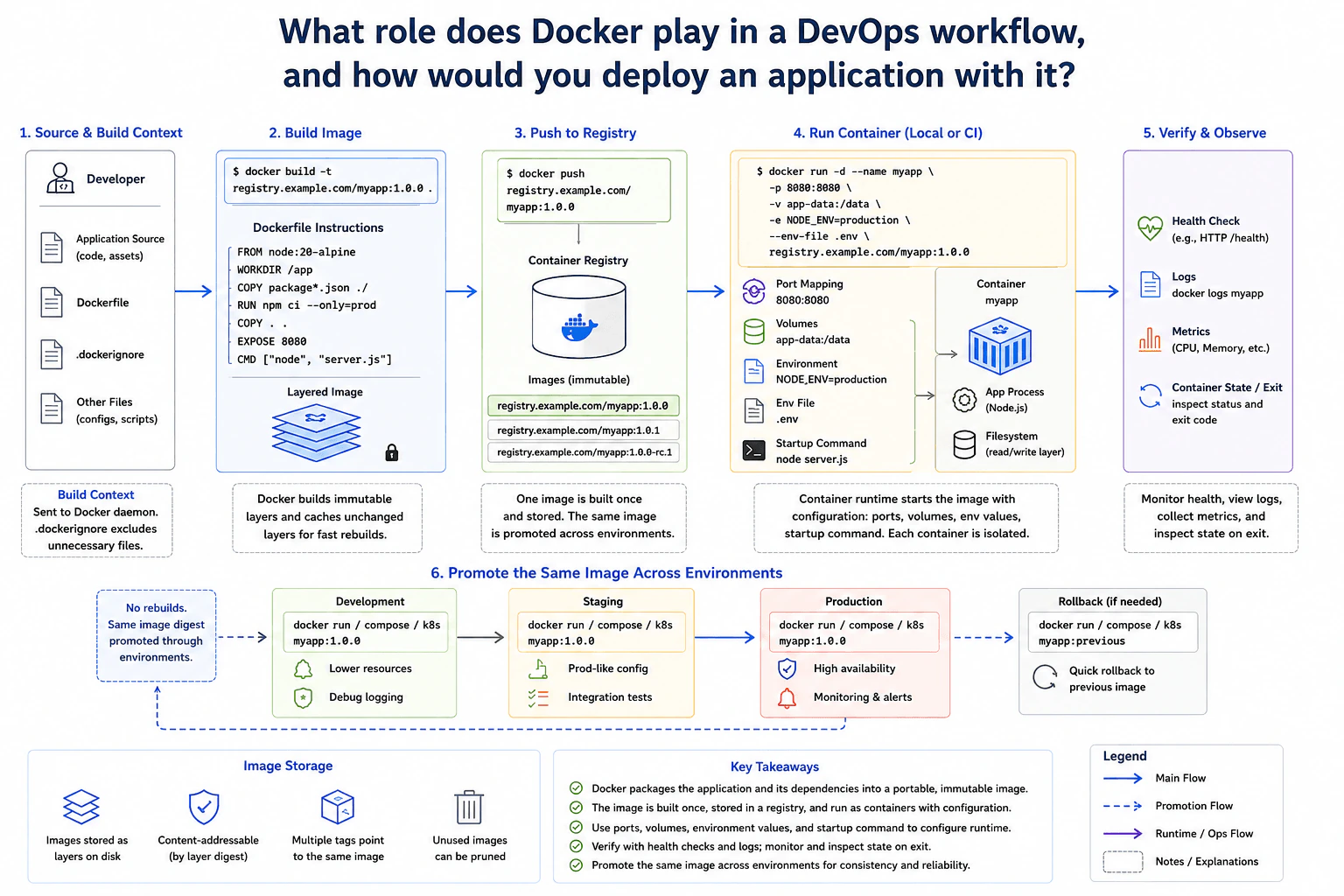
What role does Docker play in a DevOps workflow, and how would you deploy an application with it? diagram
How to Explain It in an Interview
1. Start with the source and build context

I would start with the application source, Dockerfile, and other files needed for the build. The build context is the directory Docker can read while creating the image. A .dockerignore file keeps unnecessary files out of that context. This can reduce unnecessary build input and keeps the build more focused.

2. Build the layered image

Next, Docker reads the Dockerfile and creates image layers. The diagram uses a Node base image, copies application files, installs production dependencies, exposes port 8080, and defines the startup command. Docker can reuse unchanged layers during later builds. The finished image is tagged as registry.example.com/myapp:1.0.0.

3. Push the image to the registry

After the build, I push that tagged image to the Container Registry. The registry stores and distributes the image. Images are content-addressable, which means their contents can be identified by a digest. Multiple tags can point to the same image. This stored image becomes the package used by later environments.

4. Run the container with runtime configuration

To deploy it, the container runtime starts a container from that image. Port mapping connects host port 8080 to container port 8080. A named volume mounts app-data at /data so required data can live outside the container's writable layer. Environment values such as NODE_ENV=production and an .env file provide runtime configuration. The startup command runs node server.js. The application process runs inside the container with its own writable filesystem layer.

5. Verify and promote the same image

After startup, I verify the application with an HTTP health check. I inspect logs with docker logs and watch useful runtime metrics such as CPU and memory. I also inspect the container state and exit code when it stops. Once the image is verified, I promote the same image digest through Development, Staging, and Production. I do not rebuild it for each environment. If a release fails, the diagram shows rolling back to the previous image. The benefit is consistent releases. The downside is that environment-specific values must stay outside the image and be managed carefully.

Practical Complexity & Trade-offs

The benefit is consistency. We build the application once and promote the same image through the environments. This reduces the chance that staging and production run different application packages. Reusing unchanged image layers can also make later builds faster. The downside is that runtime configuration must stay separate from the image. Ports, environment values, volumes, and startup settings must be correct when the container starts. Persistent data should not depend on the container's writable layer. Health checks and logs also matter because a running container does not automatically mean the application is healthy. Rollback is easier when the previous working image remains available.

Why Interviewers Ask This

Interviewers ask this to see whether you understand Docker as more than a command-line tool. They want to know if you can explain the full path from source code to a running container. They also look for good judgment around image layers, registries, runtime configuration, persistent data, health checks, logs, promotion, and rollback. A strong answer shows that you understand why teams build an image once and reuse that same image across environments.

Interviewer may ask next
What would you change if production needs different configuration from development and staging?

I would keep the same application image and change only the runtime configuration. That is the main reason the diagram separates the image from environment values, ports, volumes, and startup settings.

For example, Development might use debug logging and lower resources. Staging can use settings that look more like production. Production can use NODE_ENV=production, its required volume, monitoring settings, and other environment values. Those differences are supplied when the container starts. They are not baked into a new application image.

This keeps the release consistent because Development, Staging, and Production still run the same tested image digest. We are changing configuration around the image, not rebuilding the application package itself.

I would also verify the health check, logs, metrics, and container state after each promotion. If production configuration causes a failure, the diagram allows us to roll back to the previous image. The downside is that runtime configuration becomes another important part of the deployment process that must be managed correctly.

What would you do if the newly deployed container fails its health check in production?

I would first treat the failed health check as evidence that the application is not healthy. I would inspect the application logs with docker logs and check useful runtime metrics. If the process has stopped, I would also inspect the container state and exit code.

Next, I would check the runtime values shown in the diagram. I would verify the port mapping, mounted volume, environment values, .env file, and startup command. A correct image can still fail when one of those runtime settings is wrong.

If the problem cannot be corrected safely, I would use the rollback path shown in the diagram and run the previous known working image. I would not rebuild the current image just to make production different. The failed release should remain traceable as the same stored image that was tested.

The downside is that rollback depends on keeping the previous working image available and knowing exactly which image version should be restored.

5. How can you limit namespace resource consumption without editing each Deployment?Containers And KubernetesMediumAmazon

Question Details

A shared cluster needs a namespace-wide ceiling and per-container defaults while existing workload manifests omit requests and limits. Design the namespace controls, explain admission-time behavior, distinguish aggregate quota from default or bounded container values, and show how a rejected Pod and current namespace usage would be diagnosed.

Short Interview Answer (30-60 seconds)

At a high level, I would control resources at the namespace level instead of editing every Deployment. The main challenge is separating per-container defaults from the total namespace ceiling. I would explain three parts: admission, allow or reject, and diagnosis. LimitRange adds missing requests and limits and checks per-container bounds. ResourceQuota checks total namespace usage. The main limitation is that these controls affect newly admitted Pods. They do not go back and change Pods that are already running.

Detailed Explanation

The goal is to stop one namespace from consuming too much shared cluster capacity without changing every Deployment manifest. Some workloads may omit CPU and memory requests or limits. We still need sensible values when new Pods are created. We also need a ceiling for the namespace as a whole. The diagram solves these as two different controls. LimitRange handles values for each container during admission. ResourceQuota checks the combined namespace usage. Kubernetes either accepts the new object or rejects it before creation.

Useful Questions to Ask the Interviewer
  1. Which resources need namespace ceilings, such as CPU, memory, or Pod count?
  2. What default CPU and memory requests and limits should containers receive?
  3. What minimum and maximum values should each container be allowed to use?
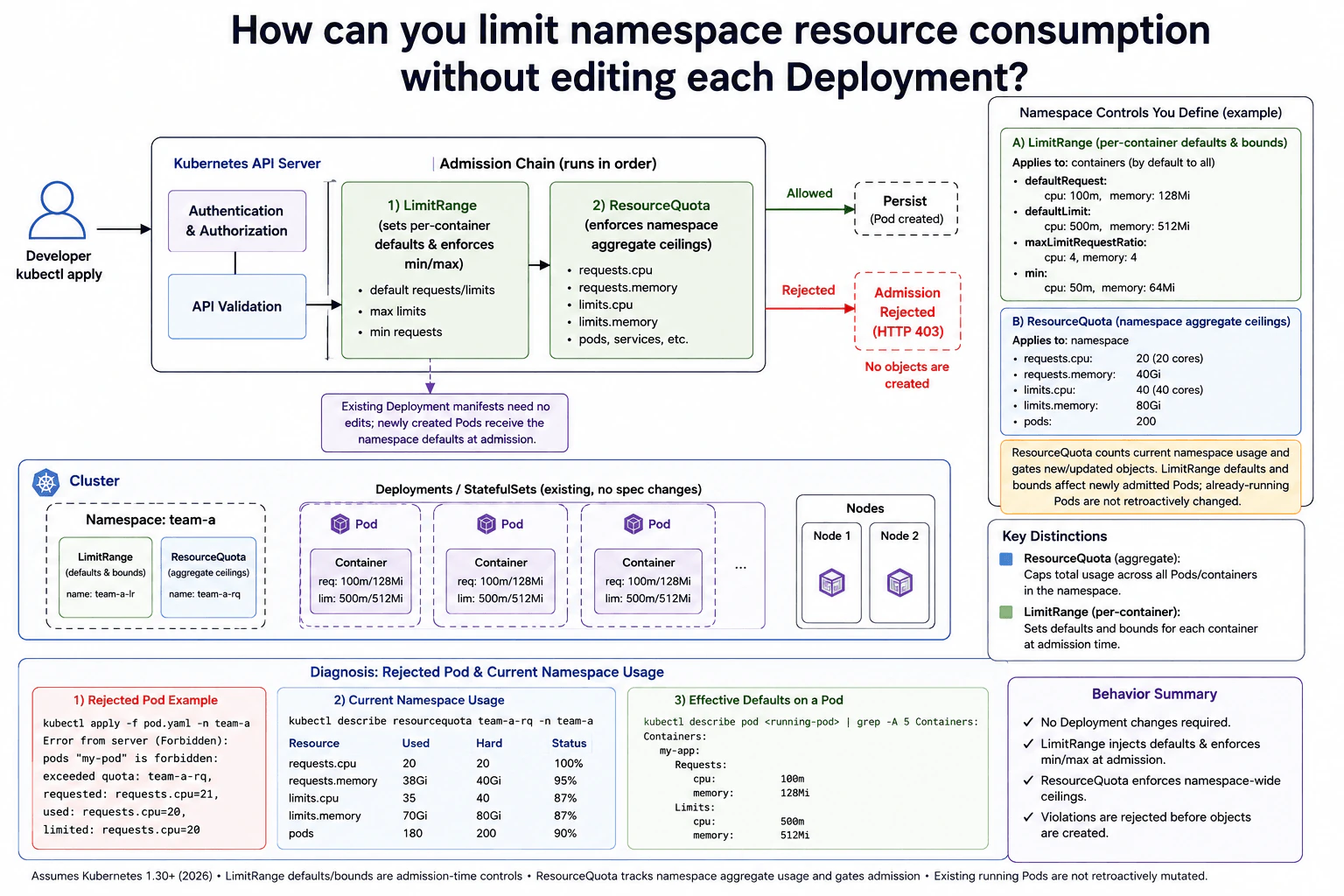
How can you limit namespace resource consumption without editing each Deployment? diagram
How to Explain It in an Interview
1. Start with namespace-level controls

I would say that the Deployment manifests can stay unchanged. The namespace contains a LimitRange and a ResourceQuota. These controls solve different problems.

LimitRange works per container. It can provide missing requests and limits. It can also reject container values that break configured minimum or maximum bounds. ResourceQuota works across the namespace. It limits the combined resource usage of all admitted workloads.

2. Follow the Kubernetes API Server admission path

A developer submits a workload with kubectl. The Kubernetes API Server performs authentication and authorization. It also validates the submitted object.

When a Pod reaches admission, LimitRange can add missing defaults. In the diagram, the example defaults are a 100m CPU request, 128Mi memory request, 500m CPU limit, and 512Mi memory limit. LimitRange can also enforce configured minimum and maximum values.

ResourceQuota then checks the namespace totals. The diagram includes ceilings for CPU requests, memory requests, CPU limits, memory limits, and Pod count. This check prevents individually valid Pods from pushing the whole namespace beyond its configured ceiling.

3. Allow or reject the Pod

If the admission checks pass, Kubernetes persists the object and the Pod can be created. A newly admitted Pod can therefore receive the values supplied by LimitRange even when its Deployment manifest did not contain them.

If the request would exceed ResourceQuota, admission rejects it with HTTP 403 Forbidden. The rejected Pod is not created. This is important during troubleshooting because there may be no rejected Pod object available to describe afterward.

4. Diagnose rejection and current namespace usage

For an admission rejection, I would first read the error returned by kubectl apply. The diagram shows an error containing the quota name and requested, used, and limited values. That tells us which quota check failed.

Next, I would run kubectl describe resourcequota team-a-rq -n team-a. The Used and Hard columns show current namespace consumption and configured ceilings. The diagram checks CPU requests, memory requests, CPU limits, memory limits, and Pods.

I would also run kubectl describe limitrange -n team-a. That shows the configured defaults and bounds. Checking both objects helps explain why the incoming Pod received certain resource values and why its admission passed or failed.

5. Explain the lifecycle limitation

The important limitation is timing. LimitRange defaults and bounds are admission-time controls. They affect newly admitted Pods. They do not go back and rewrite Pods that are already running.

ResourceQuota tracks aggregate namespace usage and gates new or updated objects. It does not directly resize or modify existing Pods. This gives namespace-wide control without requiring edits to every Deployment manifest.

Practical Complexity & Trade-offs

The benefit is that teams can control a shared namespace without changing every Deployment. LimitRange gives newly admitted containers consistent defaults and can block values outside allowed bounds. ResourceQuota gives the namespace a total ceiling, so many individually valid Pods cannot consume unlimited resources together. The downside is timing. LimitRange works when a Pod is admitted, so already-running Pods keep their current values. ResourceQuota also does not resize existing Pods. Another important trade-off is scope. LimitRange controls each container, while ResourceQuota controls the combined usage of the namespace.

Why Interviewers Ask This

Interviewers ask this to see whether you understand Kubernetes resource controls instead of only Deployment settings. They want to know if you can separate per-container rules from namespace-wide limits. They also want to see whether you understand admission-time behavior, why a Pod can be rejected before creation, and how to diagnose both the rejection and the namespace's current resource usage.

Interviewer may ask next
What happens if we add a LimitRange after many Pods are already running in the namespace?

The existing running Pods keep their current resource values. LimitRange works during Pod admission, so adding or changing it does not go back and rewrite containers that are already running.

New Pods created afterward go through the Kubernetes API Server admission path. If their manifests omit requests or limits, LimitRange can supply the configured defaults. It can also reject a new Pod when its container values break the configured minimum or maximum bounds.

This also applies to an existing Deployment. Its manifest does not need to be edited just to use the namespace defaults. When that Deployment later creates replacement or additional Pods, those new Pods are admitted under the current LimitRange rules.

The downside is that the namespace can temporarily contain Pods with different resource settings. Older Pods keep their previous values, while newer Pods receive the current defaults. Recreating or rolling out the workload is needed if every Pod must use the newer values.

How would you troubleshoot a Pod creation failure when the namespace is close to its ResourceQuota?

I would start with the error returned by kubectl apply because the Pod may never be created. A ResourceQuota rejection happens during admission, so describing the rejected Pod afterward may not work.

The error should identify the quota and show useful values such as what was requested, what is already used, and the configured limit. I would then run kubectl describe resourcequota team-a-rq -n team-a. That shows the Used and Hard values for resources such as CPU requests, memory requests, CPU limits, memory limits, and Pod count.

I would also run kubectl describe limitrange -n team-a. This matters because LimitRange may add default requests or limits during Pod admission. Those values can affect the quota calculation even when the original workload manifest omitted them.

The downside is that fixing the failure may require reducing namespace usage, increasing the quota, or changing requested values. The right choice depends on the capacity policy for that shared namespace.

6. Why can EKS Pods remain Pending even when nodes show free CPU and memory?Containers And KubernetesHardAmazon

Question Details

Investigate a workload whose scheduler never binds new Pods although aggregate node dashboards appear to have capacity. Examine scheduler events and predicates for requests, taints and tolerations, affinity, topology, ports, volume topology, quotas, Pod count limits, IP exhaustion, and node selectors. Explain how to prove the exact unsatisfied constraint before changing capacity.

Short Interview Answer (30-60 seconds)

At a high level, free CPU and memory do not guarantee that an EKS Pod can be scheduled. The scheduler needs one node that satisfies every hard placement rule. I would investigate three things: FailedScheduling events, the scheduler Filter checks, and the real state of each node. Requests, taints, selectors, affinity, topology, ports, volume topology, and Pod limits can block placement. I would prove the exact failed constraint first, because adding nodes may waste money when capacity is not the real problem.

Detailed Explanation

The cluster may show free CPU and memory, but that does not mean a new Pod has somewhere valid to run. Kubernetes must find one specific node that satisfies every hard rule for that Pod. A single rule can reject every node. The diagram solves the problem by following the scheduler path, checking the common placement constraints, and then using events and node state to prove the exact blocker. The important idea is to diagnose the failed rule before changing capacity.

Useful Questions to Ask the Interviewer
  1. Does the Pod still have no node assigned?
  2. What does its newest FailedScheduling event report?
  3. Does it use nodeSelector, affinity, topology rules, HostPort, or persistent volumes?
  4. Are any nodes at their Pod count or scheduler-visible resource limits?
  5. Is the suspected IP issue happening before binding or after binding?
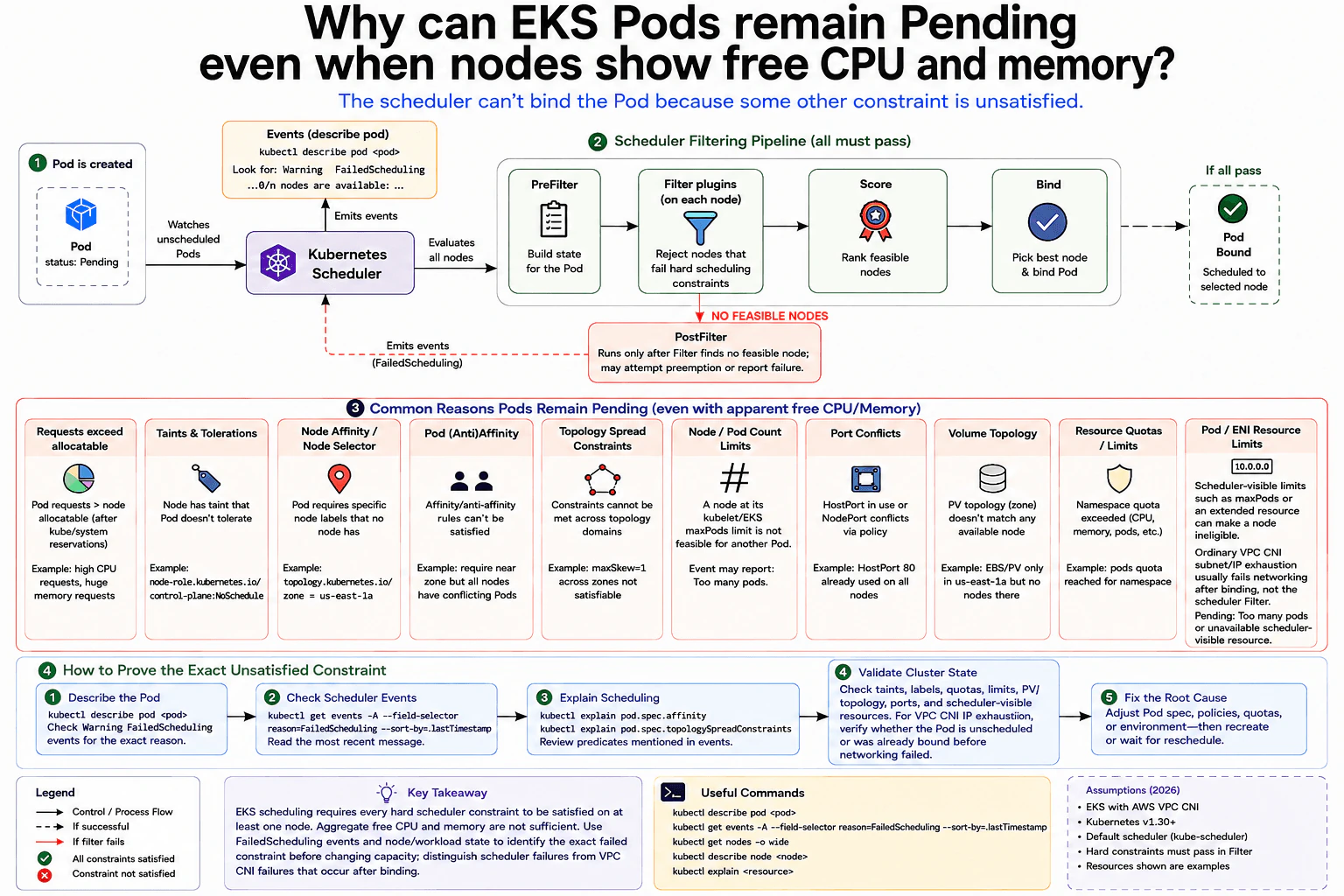
Why can EKS Pods remain Pending even when nodes show free CPU and memory? diagram
How to Explain It in an Interview
1. Start with the real scheduling rule

I would start by saying that aggregate capacity can be misleading. The scheduler needs at least one feasible node, meaning one node that passes every hard scheduling constraint.

The Pod begins unscheduled. The Kubernetes Scheduler watches for it and builds scheduling state during PreFilter. Filter plugins then examine candidate nodes and reject nodes that cannot run the Pod.

Only feasible nodes continue to Score. Score ranks those nodes. Bind then assigns the Pod to the chosen node.

If Filter finds no feasible node, the normal Score and Bind path cannot continue. PostFilter runs on that failure path. It can try actions such as preemption or report the scheduling failure.

2. Read FailedScheduling events first

My first command would be kubectl describe pod <pod>. I would read the Events section and look for FailedScheduling.

That message is more useful than an aggregate dashboard. It tells me why candidate nodes were rejected. I can also list recent FailedScheduling events and inspect the newest message.

3. Check the hard placement constraints

Then I would verify the constraint named by the event. Pod resource requests may exceed a node's remaining allocatable CPU or memory even when the whole cluster shows free resources.

Taints require matching tolerations. A nodeSelector or required node affinity can require labels that no node has. Pod affinity, anti-affinity, and topology spread constraints can also leave no valid placement.

A HostPort request can conflict with a port already reserved on a node. Volume topology can block placement when a persistent volume is tied to a zone without a suitable node. A node that has reached its kubelet or EKS maxPods limit is also not feasible. The scheduler may report Too many pods.

Namespace ResourceQuota and LimitRange should also be checked, but I would distinguish them from scheduler filtering. They normally act during admission and can reject or change a Pod before scheduling rather than make an already accepted Pod fail a scheduler Filter check.

4. Separate scheduler limits from VPC CNI failures

I would be careful with IP exhaustion. A scheduler-visible limit such as maxPods, or a requested extended resource, can make a node ineligible before binding.

Ordinary AWS VPC CNI subnet or ENI IP exhaustion is different. It commonly causes networking setup to fail after the scheduler has already bound the Pod. I would first verify whether the Pod has a node assigned before calling IP exhaustion the scheduling cause.

5. Prove the blocker, then change only that cause

I would use kubectl explain for affinity or topology settings, inspect node labels and taints, describe nodes, and compare requests with per-node capacity. I would also validate ports, persistent-volume topology, Pod count limits, quotas, and scheduler-visible resources.

Once the failed constraint is proven, I would change only that issue. I might adjust requests, tolerations, selectors, affinity, topology rules, ports, storage placement, quotas, or node limits. I would add capacity only when the evidence shows that real per-node capacity is the blocker.

Practical Complexity & Trade-offs

The benefit is that this method finds the real blocker before changing the cluster. FailedScheduling events often show exactly why nodes were rejected. The downside is that several rules can interact, so one CPU graph is not enough. You may need to inspect requests, taints, labels, affinity, topology, ports, storage, and Pod limits together. IP problems also need care because ordinary VPC CNI exhaustion can happen after scheduling. We accept this extra investigation because adding nodes for the wrong reason increases cost and may leave the real scheduling problem unchanged.

Why Interviewers Ask This

Interviewers want to see whether you understand how Kubernetes makes placement decisions. They are testing whether you can move beyond a simple CPU and memory dashboard, use scheduler evidence, and identify one exact failed rule. They also want to see whether you can distinguish a true scheduling failure from a networking problem that happens after the Pod is already bound.

Interviewer may ask next
What would you do if FailedScheduling says every node has insufficient CPU, but the monitoring dashboard shows free CPU?

I would trust the scheduler's per-node resource calculation before the aggregate dashboard. Kubernetes schedules from Pod requests and node allocatable resources, not from current CPU usage alone.

I would inspect the new Pod's CPU request. Then I would compare that request with the remaining requested CPU on each individual node. Existing Pods may reserve CPU through their requests even when they are not currently using all of it.

The important point is that free CPU on several nodes cannot be combined for one Pod. One node must have enough allocatable capacity for the complete request and must still pass every other hard constraint.

If no node has enough room, then capacity is a proven blocker. I could correct an unrealistic Pod request or provide a suitable node with more capacity. The downside of adding capacity is extra cost, so I would verify the requests first.

How would you investigate a claim that AWS VPC CNI IP exhaustion is keeping these Pods Pending?

I would first determine whether the Pod is truly unscheduled. I would check the Pod's node assignment and read its events.

If the scheduler reports a reason such as Too many pods, then a scheduler-visible limit like maxPods may be preventing placement. I would investigate that as part of the Filter path shown in the diagram.

If the Pod already has a node assigned, ordinary subnet or ENI IP exhaustion is usually a later networking problem. The scheduler has already completed Bind, and the VPC CNI then cannot prepare networking for the Pod.

That distinction keeps the diagnosis accurate. Otherwise, I could change scheduler rules or add nodes for a failure that actually happens after scheduling. I would correlate the Pod phase, node assignment, FailedScheduling events, and VPC CNI networking evidence before making a change. The downside is that this requires checking both scheduling state and networking state.

7. What is the difference between a Terraform local value and an input variable?Infrastructure As CodeEasyAmazon

Question Details

Compare where each value originates, who can set it, its scope, type checking, evaluation, and appropriate use in a root module or child module. Include one case where a caller must supply a value and one case where a repeated expression should be computed internally, without treating either construct as secret storage.

Short Interview Answer (30-60 seconds)

Use an input variable for values a caller can configure from outside a module. Use a local value for values computed and reused inside that module. Variables can declare type constraints and defaults; locals derive their type from expressions. Neither is secret storage.

Detailed Explanation

See the Code while reading this explanation.

This question asks about two ways to give names to values in a reusable setup. One is for information that can come from a person, a file, or another part of the setup. The other is for information calculated inside one part so the same calculation does not need to be repeated. You should explain who chooses each value, where it can be used, when it becomes known, and which choice makes the setup easier to understand, reuse, and maintain without treating either choice as a safe place for private information.

Useful Questions to Ask the Interviewer
  1. Should I compare both root-module and child-module behavior?
  2. Should I include one required caller input and one internally reused expression?
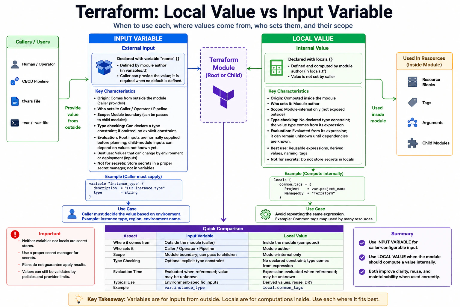
What is the difference between a Terraform local value and an input variable? diagram
How to Explain It in an Interview

Start with the practical rule: if a value is part of the module's external configuration, use an input variable. If a value is derived inside the module and should not be directly configurable by the caller, use a local value.

An input variable is declared with a variable block and referenced with var.<name>. Its value comes from outside the module boundary. In a root module, the value may be provided by a human or operator, a CI/CD pipeline, a .tfvars file, -var, -var-file, environment-based Terraform input, or a declared default. In a child module, the parent module supplies values through arguments in the child module call. A variable can declare a type constraint such as string. If a variable has no default, the caller must supply its value.

A local value is declared in a locals block and referenced with local.<name>. Its expression is defined by the module author and computed inside that module. The caller cannot directly set or override a local value. Locals are useful for derived values, naming rules, common tags, and repeated expressions that should be written once and reused in resource arguments, tags, or values passed onward to child modules. A local has no separately declared type constraint; its resulting type comes from its expression.

The scope is also different. An input variable belongs to the module where it is declared. A parent module can explicitly pass a value across a module boundary into a child's declared input variable. A local value is module-internal. A child module does not automatically inherit locals from its parent. If a child needs a value derived by the parent, the parent passes the resulting value through one of the child's input variables.

Evaluation needs a careful explanation. Root-module input values are normally supplied before planning, but a child-module input can be assigned an expression whose result is not known yet. A local is evaluated from its expression when referenced and can also remain unknown until its dependencies become known. Terraform propagates unknown values through expressions rather than requiring every variable or local to be fully known at the start of planning.

For a caller-supplied case, imagine a reusable module needs an instance_type and there is no safe universal default. Declare variable "instance_type" and let the caller choose the value. For an internal-computation case, imagine several resource blocks need the same common_tags map. Compute that map once in locals and reuse local.common_tags instead of repeating the expression.

Neither input variables nor locals are secret storage. A variable can be marked sensitive to reduce accidental display in some Terraform output, but that does not make it encrypted secret storage. Sensitive values can still be stored in Terraform state or reach other systems depending on how they are used. Use an appropriate secret-management mechanism and protect state, outputs, logs, and command usage accordingly.

The simple rule is: values from outside use variables; values computed inside use locals. Keep the module interface explicit and small, and use locals to remove repetition and keep implementation details inside the module.

Key Insight / Why This Solution Works
  1. Ask whether the caller should be able to choose or change the value. If yes, use an input variable.
  2. Decide whether the variable needs an explicit type constraint and whether a safe default exists.
  3. If the value is derived from other values and is only an internal implementation detail, define it as a local.
  4. Pass values across parent-child module boundaries through declared child-module inputs; do not assume locals are shared.
  5. Allow for variables or locals to remain unknown while their dependencies are unresolved.
  6. Use a proper secret-management workflow instead of treating either construct as secret storage.
Code
code = '# Caller-configurable input. There is no default, so the caller must supply this value.\nvariable "instance_type" {\n  description = "EC2 instance type"\n  type        = string\n}\n\n# Explicit caller input used by the module to derive a reusable internal value.\nvariable "project_name" {\n  description = "Project name used to build common tags"\n  type        = string\n}\n\n# Module-owned calculation. The caller cannot directly override this local value.\n# Its type comes from this expression, and it can be reused wherever the module needs these tags.\nlocals {\n  common_tags = {\n    Project   = var.project_name\n    ManagedBy = "Terraform"\n  }\n}\n\n# Inside this module, configuration can reference var.instance_type for caller-selected behavior\n# and local.common_tags for the internally computed reusable map.\n# A parent may also pass a resulting value to a child module through that child\'s declared inputs.\n# Do not place secrets here; use an appropriate secret-management workflow instead.'
Why Interviewers Ask This

Interviewers want to see whether you understand Terraform module boundaries and can distinguish caller-controlled configuration from values derived inside a module. A strong answer also shows that you understand type constraints, evaluation of unknown values, root-module and child-module behavior, reusable expressions, and why neither variables nor locals are secret-storage mechanisms.

Common interview mistakes

Common mistakes are saying an input variable must always be supplied even when it has a default; saying callers can override locals; assuming a child module automatically inherits a parent's locals; saying every variable must declare a type constraint; saying all variable values are always known before planning; saying locals are always fully known during planning; and treating either variables or locals as secure secret storage. Another mistake is exposing internal calculations as unnecessary input variables, which makes the module interface larger and harder to maintain.

Interview tip

Lead with one rule: caller-configurable value means input variable; internally derived value means local. Then compare origin, who sets it, scope, type behavior, and evaluation. Give one required-input example and one repeated-expression example, and finish by stating that neither construct is secret storage.

Interviewer may ask next
Can a child module directly use a local value defined in its parent module?

No. A local value is scoped to the module where it is declared. A child module does not automatically inherit the parent's locals. If the child needs that value, the parent must pass the resulting value through one of the child module's declared input variables.

Are Terraform input variables always known before the plan, while local values are always calculated during the plan?

No. Root-module inputs are normally supplied before planning, but a child-module input can receive an expression whose result is not known yet. A local is evaluated from its expression when referenced and can also remain unknown while its dependencies are unknown. Terraform propagates unknown values until enough information becomes available.

8. What happens internally when Terraform applies two modules with interdependencies?Infrastructure As CodeMediumAmazon

Question Details

Explain how configuration is loaded, providers and modules are initialized, expressions create implicit edges, explicit dependencies alter the graph, unknown values affect planning, and graph nodes are scheduled during apply. Include failure behavior when an upstream resource is created but a dependent operation fails, and how the next plan determines remaining work.

Short Interview Answer (30-60 seconds)

Terraform builds a dependency graph from references and explicit depends_on rules, plans with unknown values where necessary, and applies dependency-ready nodes, running independent work concurrently when possible. Completed changes can remain after a failure, and the next plan refreshes current state and recalculates the remaining work.

Detailed Explanation

This question asks what happens behind the scenes when one reusable infrastructure part needs values or resources created by another part. Terraform first reads the configuration and understands how the pieces relate. It checks what already exists, works out what must change, and waits for required earlier work before starting dependent work. Independent work can happen at the same time. If later work fails, earlier completed work can remain. On the next attempt, Terraform checks the current real environment again and works out what still needs to be created or changed.

Useful Questions to Ask the Interviewer
  1. Should I assume both modules are called from the same root configuration and use the same Terraform state?
  2. Do you want me to explain both reference-based dependencies and explicit depends_on dependencies?
  3. Should I include partial-apply failure behavior and what happens during the next terraform plan?
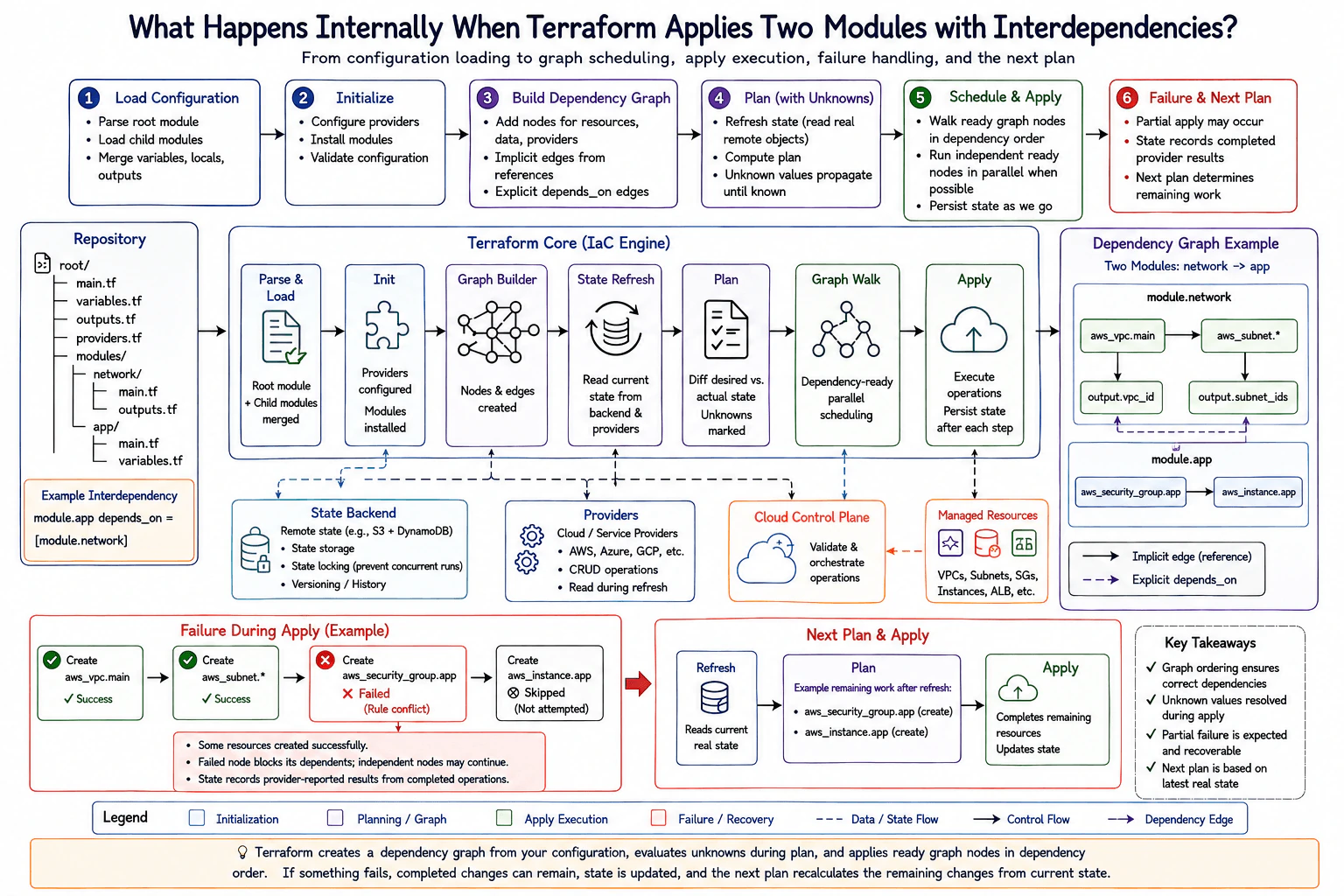
What happens internally when Terraform applies two modules with interdependencies? diagram
How to Explain It in an Interview

Assume modern Terraform 1.x behavior as of 2026. Both child modules are called from one root configuration and participate in the same Terraform graph and state. Provider API behavior can vary, but dependency construction, unknown-value handling, graph walking, and state coordination are Terraform Core concepts.

1. Terraform loads the configuration

Terraform reads the root module and the referenced child modules. It evaluates configuration structure such as variables, locals, module inputs, outputs, resource addresses, provider requirements, and expressions.

The important point is that Terraform does not treat the files as a script that runs from top to bottom. File order does not define resource creation order.

2. Terraform initializes modules and providers

During initialization, Terraform makes the referenced child modules and required provider plugins available. Terraform Core later uses configured provider instances to read remote objects and perform create, update, or delete operations.

Terraform Core decides dependency ordering and graph scheduling. Providers are responsible for translating Terraform resource operations into calls to the external platform, such as a cloud control plane.

3. Expressions create implicit dependency edges

Suppose the application module consumes values produced by the network module, such as a VPC ID or subnet IDs. A reference such as module.network.vpc_id creates an implicit dependency because Terraform can see that the consuming expression depends on the upstream value.

This is normally the preferred way to express dependencies. The data flow itself tells Terraform what must be ready first.

4. depends_on adds an explicit dependency

Terraform also supports depends_on for relationships that cannot be expressed through a normal value reference. A module-level relationship such as depends_on = [module.network] adds an explicit ordering constraint between the dependent module and the network module.

Explicit dependencies should be used carefully. Broad dependencies can reduce safe concurrency and can cause additional values to remain unknown during planning because Terraform must wait for a wider set of upstream operations.

5. Terraform builds the dependency graph

Terraform Core creates a directed graph of the operations it must evaluate or perform. Resources, data-source operations, provider-related operations, module-related operations, and other internal nodes participate in this graph.

The graph captures both implicit relationships discovered from expressions and explicit relationships added with depends_on. This graph, not file order, determines which operations can become ready.

6. Terraform refreshes current state and creates a plan

Terraform reads its stored state and normally asks providers to read the corresponding remote objects. This refresh gives Terraform a current view of what the providers report exists.

Terraform then compares desired configuration with the refreshed current state and creates a plan. The plan is a preview based on what Terraform knows at that moment; it is not a guarantee that every later provider operation will succeed.

7. Unknown values are carried through the plan

Some values cannot be known until an upstream resource is actually created. Examples include provider-generated IDs or other computed attributes.

Terraform represents these values as unknown during planning instead of guessing them. Expressions that depend on those values can also remain partially unknown. During apply, when the upstream provider operation completes and reports the real value, Terraform can use it for downstream work.

8. Apply is a dependency-ready graph walk

During apply, Terraform walks the graph and schedules nodes whose dependencies have completed successfully. It is not a single rigid sequential ordering of every node.

In the diagram's example, network resources such as the VPC and subnets are upstream of application resources that depend on their outputs. Those dependent application operations wait until their required network values are available.

Independent graph nodes can be executed concurrently when they are ready, subject to Terraform's configured parallelism and any provider or cloud-platform limitations.

9. Providers perform the real platform operations

Terraform Core asks the appropriate provider to perform each resource operation. The provider then communicates with the external cloud or service control plane.

When a completed operation returns provider-reported results, Terraform updates its state information. With a locking-capable backend, Terraform also protects state-changing operations against unsafe concurrent writers. The exact locking mechanism depends on the configured backend and Terraform version.

10. A partial failure does not automatically roll back successful resources

Assume the VPC and subnets are created successfully, but creation of a dependent security group fails. Terraform does not automatically perform a transactional rollback of the successfully created upstream resources.

The failed node blocks downstream nodes that depend on it. For example, an instance that requires the failed security group cannot become ready. Independent work that is not dependent on the failed node may already be running or may continue where scheduling allows.

Provider-reported results from completed operations can be recorded in state. This lets Terraform distinguish infrastructure that already exists from infrastructure that still needs work.

11. The next plan recalculates remaining work

After correcting the cause of the failure, the normal recovery approach is to run a new plan.

Terraform does not simply resume the previous apply at the failed line. It reloads the configuration, reads state, refreshes relevant remote objects through the providers, and compares the current real environment with the desired configuration again.

Resources that already match the desired configuration are normally no-ops. Missing, failed, changed, or drifted resources become proposed changes in the new plan. In the diagram's failure example, the already-created network resources remain, while the failed security-group creation and the dependent instance creation can appear as the remaining work.

Main tradeoff

Precise dependencies give Terraform the best execution graph. Expression-based references usually provide the clearest and narrowest relationships, which allows more safe concurrency. Unnecessary broad depends_on relationships can serialize work and make more values unknown during planning.

The safest recovery model after a partial failure is usually forward-fix: correct the underlying problem, run a fresh plan, review it, and apply the newly calculated changes rather than assuming automatic rollback or manually editing state.

Technical Approach
  1. Load the root configuration and referenced child modules.
  2. Initialize required modules and provider plugins.
  3. Evaluate variables, locals, module inputs, outputs, resource addresses, and expressions.
  4. Create implicit dependency edges from references between values.
  5. Add explicit ordering constraints from depends_on where they are genuinely required.
  6. Build the dependency graph used by Terraform Core.
  7. Read stored state and refresh relevant remote objects through providers.
  8. Compare desired configuration with refreshed current state and produce a plan.
  9. Keep provider-computed values unknown when they cannot be known before apply.
  10. During apply, schedule graph nodes when their dependencies have completed successfully.
  11. Run independent ready nodes concurrently when possible.
  12. Send real resource operations through providers to the external control plane.
  13. Record provider-reported results from completed operations in state.
  14. If a node fails, block its downstream dependents while unrelated eligible work may continue or finish.
  15. End the failed apply without automatically rolling back successfully completed resources.
  16. Correct the failure and run a new plan.
  17. Refresh current remote objects again and calculate the remaining required changes from the current state.
Practical Insights

The main cost is operational rather than normal algorithm complexity. More graph nodes mean more dependency evaluation, provider API calls, remote reads, and state updates. Independent nodes can run at the same time, which can shorten apply time, but provider limits, cloud quotas, and Terraform parallelism can limit concurrency. Broad explicit dependencies can make more work wait and can make additional values unknown during planning. Partial failures also add operational cost because Terraform must refresh the current environment, produce another plan, review it, and perform another apply.

Why Interviewers Ask This

Interviewers want to confirm that you understand Terraform as a dependency-graph engine rather than a tool that simply executes files or modules from top to bottom. The question tests configuration loading, provider and module initialization, implicit and explicit dependencies, unknown values, graph scheduling, state handling, partial failures, concurrency, and recovery through a fresh plan.

Common interview mistakes

Common mistakes are saying Terraform runs files or modules in declaration order; treating each module as one indivisible execution step; assuming every dependency requires depends_on; forgetting that value references create implicit dependency edges; calling unknown planned values errors; assuming apply is completely sequential; assuming a failed node necessarily stops every unrelated operation immediately; claiming Terraform automatically rolls back resources created before a failure; treating state as the remote infrastructure itself; assuming the next apply simply resumes the previous command at the failed operation; manually editing state as a normal recovery step; and forgetting that the next plan refreshes current remote objects and recalculates what is still required.

Interview tip

Explain the flow in one sequence: load configuration, initialize modules and providers, build implicit and explicit dependency relationships, refresh state, plan with unknown values, walk dependency-ready nodes during apply, record completed provider results, handle partial failure without automatic rollback, and run a fresh plan to recalculate remaining work. Emphasize that the graph determines ordering, not file order.

Interviewer may ask next
What is the difference between an implicit dependency and depends_on in Terraform?

An implicit dependency is inferred automatically from an expression reference. For example, if the application module consumes module.network.vpc_id, Terraform knows the consuming work depends on the network output and adds the required graph relationship. depends_on adds an explicit ordering constraint when the dependency cannot be represented naturally through a value reference. Prefer implicit dependencies when possible because broad explicit dependencies can reduce concurrency and make more values unknown during planning.

If upstream network resources are created successfully but a dependent application resource fails, what happens on the next Terraform run?

Terraform does not automatically roll back the successfully created upstream resources. Provider-reported results from completed operations can remain recorded in state, and downstream nodes that depend on the failed operation are blocked. After the cause is corrected, a new plan refreshes the current remote objects and compares them with the desired configuration. Resources that already match are normally no-ops, while missing, failed, changed, or drifted resources appear as the recalculated remaining work.

9. How would you represent a blue-green deployment with weighted target groups as Infrastructure as Code?Infrastructure As CodeHardAmazon

Question Details

Model two launch-template and Auto Scaling Group versions behind separate ALB target groups, with listener forwarding weights controlling traffic. Include Secrets Manager references, health and readiness gates, capacity during overlap, immutable artifact identity, promotion steps, instant rollback, state transitions, and safeguards that prevent an apply from deleting the known-good environment before the new one is verified.

Short Interview Answer (30-60 seconds)

I would model Blue and Green as separate launch templates, Auto Scaling Groups, and ALB target groups, then control traffic with listener weights. Green must pass readiness gates first, both environments overlap during rollout, and Terraform lifecycle, policy, state locking, and review protect Blue for instant rollback.

Detailed Explanation

See the Code while reading this explanation.

The goal is to release a new version without removing the version that already works. I keep the old and new environments running at the same time. Users first stay on the old environment. After the new environment starts and passes its checks, I send it a small share of users. If it stays healthy, I increase that share step by step until all users reach the new version. If something goes wrong, I send users back to the old version immediately. I remove or reduce the old environment only after the new version has stayed stable long enough.

Useful Questions to Ask the Interviewer
  1. Should Blue stay running as a warm rollback environment after Green reaches 100% traffic?
  2. Which target health, application readiness, error-rate, latency, and business checks must pass before each traffic increase?
  3. What traffic progression should be used, for example 100/0, 90/10, 50/50, 10/90, then 0/100?
  4. Must each Auto Scaling Group be able to handle full production load during the overlap?
  5. Should production promotion require both policy approval and a human approval?
  6. How long should the stabilization window last before Blue can be scaled down or removed?
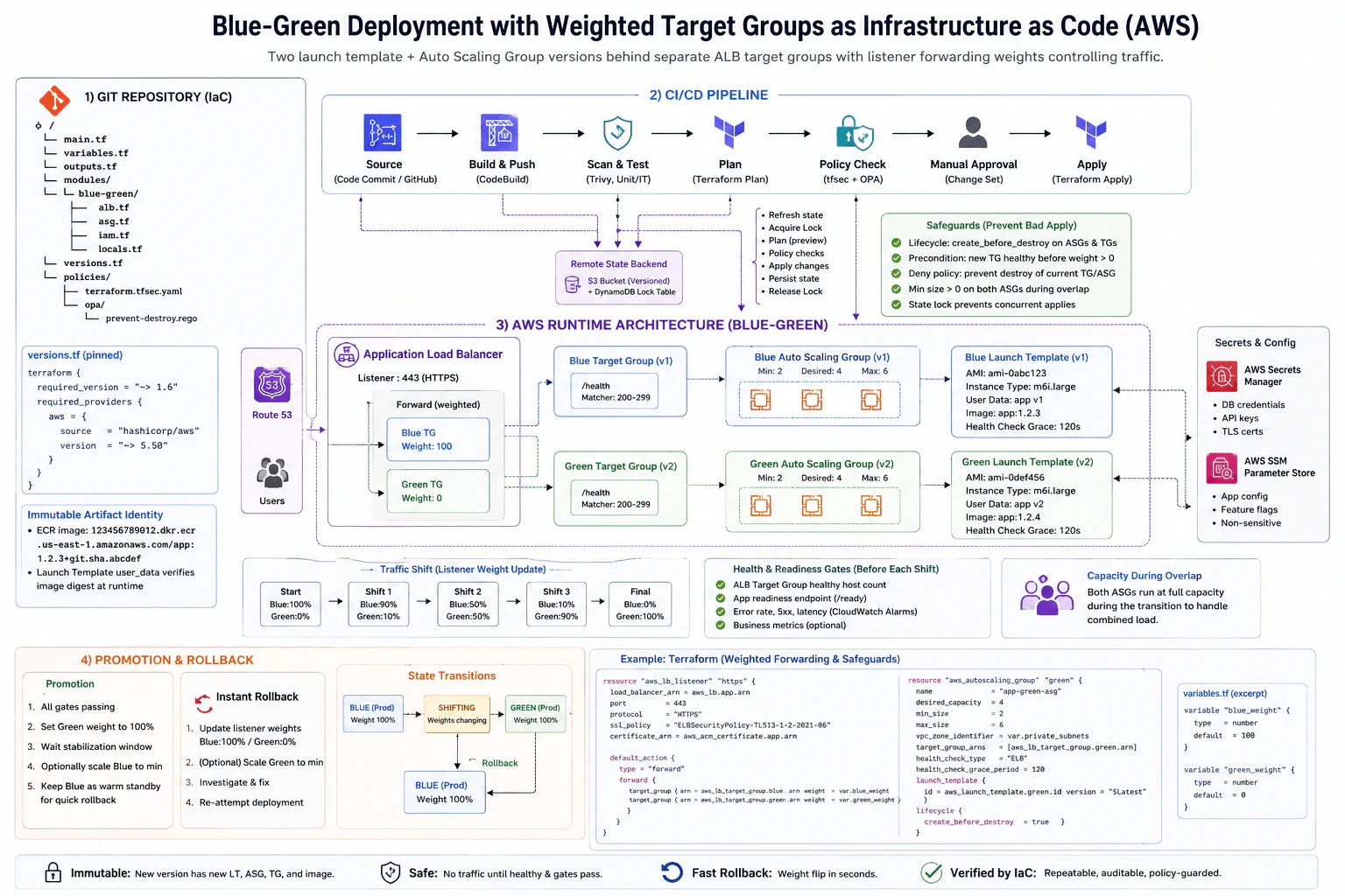
How would you represent a blue-green deployment with weighted target groups as Infrastructure as Code? diagram
How to Explain It in an Interview

I would represent Blue and Green as separate Terraform-managed resource identities. Blue has launch template v1, Blue Auto Scaling Group v1, and Blue target group v1. Green has launch template v2, Green Auto Scaling Group v2, and Green target group v2. I would not mutate the Blue ASG into Green because that removes the clean rollback boundary.

The ALB listener is the traffic-control point. Its weighted forward action references both target groups. The normal starting state is Blue 100 and Green 0. After Green is created and verified, I move traffic through controlled states such as Blue 90/Green 10, Blue 50/Green 50, Blue 10/Green 90, and finally Blue 0/Green 100. Changing the weights does not require rebuilding either environment.

The deployment artifact must also be immutable. In the diagram, each launch-template version is tied to a specific application version, and the artifact identity is represented by a pinned ECR image and digest. The launch template user data can start that exact version and verify the expected digest at runtime. This prevents a mutable tag from silently changing what a previously reviewed deployment means.

Both Auto Scaling Groups run during the transition. The diagram shows each ASG with minimum 2, desired 4, and maximum 6 instances. That overlap costs more, but it allows Green to be tested under real load without taking away Blue capacity. I would size the overlap so either environment can still satisfy the required production load if rollback is needed.

Green must not receive production traffic simply because Terraform successfully created its resources. Before every traffic increase, I require the ALB target group to have enough healthy hosts, the application's readiness endpoint to succeed, and the required error-rate, latency, and CloudWatch alarm gates to remain acceptable. The diagram uses /health with HTTP 200-299 matching and a launch health-check grace period. The delivery pipeline treats these checks as promotion gates rather than assuming resource creation equals application readiness.

Secrets stay outside source code and outside Terraform values that would expose them in state. Terraform can reference the Secrets Manager secret metadata or ARN, while the instance role retrieves the actual value at runtime with least privilege. Non-secret application configuration can be referenced from AWS Systems Manager Parameter Store. I would not put database passwords, API keys, TLS private material, or other secret values in Git, Terraform outputs, command lines, or CI logs.

The delivery path is source change, build and test, security scanning, Terraform plan, policy checks, manual approval, and Terraform apply. The diagram also shows remote Terraform state in a versioned S3 bucket with a DynamoDB lock table because its repository example pins Terraform ~> 1.6. The production run refreshes observed state, obtains the lock, produces a plan, passes policy and human review, applies the approved change, persists the resulting state, and releases the lock. The lock prevents concurrent production applies from racing with one another.

I would explain that terraform plan is still only a preview based on the configuration, stored state, and remote objects observed at that time. Permissions, quotas, provider behavior, eventual changes in remote objects, or another external action can still cause apply to fail. If an apply partially succeeds, I first inspect the actual remote resources and refreshed Terraform state, then create a new reviewed plan for a forward fix or rollback. I would not manually edit state as the normal recovery method.

The key safety requirement is that one apply must not remove the known-good Blue environment before Green is verified. I use create_before_destroy where replacement ordering is appropriate, prevent_destroy on the currently protected Blue resources, policy checks that reject plans deleting the current Blue target group or ASG, and a promotion precondition that prevents Green from receiving traffic until the external verification gate has passed. prevent_destroy is deliberately removed only in a later reviewed change when Blue is no longer the rollback environment.

The deployment state transitions are explicit: Blue active -> shifting -> Green active. During shifting, traffic weights change gradually and every step has a verification gate. After Green reaches 100%, I keep Blue available through a stabilization window. If Green fails, rollback changes the listener back to Blue 100/Green 0. Because Blue was not destroyed, this is a fast traffic change rather than a rebuild.

The main tradeoff is additional temporary cost versus much faster recovery. Running both ASGs during the overlap can approach twice the normal compute capacity, but it gives safer validation and a predictable rollback path. The design separates provisioning, verification, promotion, and later decommissioning so that successful infrastructure creation is never confused with a safe production release.

Key Insight / Why This Solution Works
  1. Pin the Terraform, AWS provider, module, and policy versions used by the repository.
  2. Give Blue and Green separate launch templates, Auto Scaling Groups, target groups, and immutable artifact identities.
  3. Keep secret values outside Terraform and let the instance role retrieve them from Secrets Manager at runtime.
  4. Store Terraform state remotely and prevent concurrent production applies with backend locking.
  5. Run formatting, validation, tests, security scans, policy checks, state refresh, and terraform plan.
  6. Review and approve the production plan before apply.
  7. Create Green while Blue remains active and preserve enough overlap capacity for both ASGs.
  8. Wait until Green passes target health, readiness, error-rate, latency, and alarm gates.
  9. Start with Blue 100/Green 0 and shift through approved weight stages such as 90/10, 50/50, 10/90, then 0/100.
  10. Re-run verification gates before each increase.
  11. If a gate fails, restore Blue 100/Green 0 while Blue is still running.
  12. After Green reaches 100%, wait through the stabilization window.
  13. Remove Blue protection or reduce Blue capacity only in a separate reviewed change after Green is accepted as the new known-good environment.
Code
# The supplied source is Terraform HCL; keep it verbatim while making this a valid Python 3.14 module.
TERRAFORM_CONFIGURATION = r"""terraform {
  # Match the repository-pinned engine shown in the approved design.
  required_version = "~> 1.6"

  # Pin the provider family because AWS resource schemas and replacement behavior are provider-specific.
  required_providers {
    aws = {
      source  = "hashicorp/aws"
      version = "~> 5.50"
    }
  }

  # Production initializes this S3 backend with reviewed environment-specific settings.
  # For the pinned Terraform version in this design, the backend configuration includes
  # a versioned S3 bucket and DynamoDB locking, but their real names are not hard-coded here.
  backend "s3" {}
}

provider "aws" {
  # CI supplies least-privilege credentials through its workload identity, not static keys.
  region = var.aws_region
}

variable "aws_region" {
  type        = string
  description = "AWS Region containing the Blue-Green environment."
}

variable "vpc_id" {
  type        = string
  description = "VPC shared by both ALB target groups."
}

variable "private_subnet_ids" {
  type        = list(string)
  description = "Private subnets used by both Auto Scaling Groups."
}

variable "instance_security_group_ids" {
  type        = list(string)
  description = "Security groups attached to Blue and Green EC2 instances."
}

variable "alb_arn" {
  type        = string
  description = "ARN of the existing Application Load Balancer."
}

variable "certificate_arn" {
  type        = string
  description = "ACM certificate ARN for the HTTPS listener."
}

variable "base_ami_id" {
  type        = string
  description = "Pinned AMI used by the launch templates."
}

variable "blue_image_uri" {
  type        = string
  description = "Immutable Blue application image URI including its reviewed digest."
}

variable "green_image_uri" {
  type        = string
  description = "Immutable Green application image URI including its reviewed digest."
}

variable "app_secret_name" {
  type        = string
  description = "Secrets Manager name; Terraform reads metadata only, never the secret value."
}

variable "blue_weight" {
  type        = number
  description = "ALB listener weight for Blue."
  default     = 100

  validation {
    condition     = var.blue_weight >= 0 && var.blue_weight <= 100
    error_message = "blue_weight must be between 0 and 100."
  }
}

variable "green_weight" {
  type        = number
  description = "ALB listener weight for Green."
  default     = 0

  validation {
    condition     = var.green_weight >= 0 && var.green_weight <= 100
    error_message = "green_weight must be between 0 and 100."
  }
}

variable "green_verified" {
  type        = bool
  description = "Set true by the reviewed delivery stage only after Green passes health and readiness gates."
  default     = false
}

# Read secret metadata only. The actual secret value never enters Terraform state.
data "aws_secretsmanager_secret" "app" {
  name = var.app_secret_name
}

# Instances assume this role so the application retrieves its secret at runtime.
resource "aws_iam_role" "app" {
  name = "blue-green-app-role"

  assume_role_policy = jsonencode({
    Version = "2012-10-17"
    Statement = [{
      Effect = "Allow"
      Principal = {
        Service = "ec2.amazonaws.com"
      }
      Action = "sts:AssumeRole"
    }]
  })
}

# Least privilege allows only the application secret required by this deployment.
resource "aws_iam_role_policy" "app_secret" {
  name = "read-app-secret"
  role = aws_iam_role.app.id

  policy = jsonencode({
    Version = "2012-10-17"
    Statement = [{
      Effect   = "Allow"
      Action   = ["secretsmanager:GetSecretValue"]
      Resource = data.aws_secretsmanager_secret.app.arn
    }]
  })
}

resource "aws_iam_instance_profile" "app" {
  # The launch templates use this profile rather than embedding AWS credentials.
  name = "blue-green-app-profile"
  role = aws_iam_role.app.name
}

resource "aws_lb_target_group" "blue" {
  # Blue remains a separately addressable rollback target.
  name     = "app-blue"
  port     = 80
  protocol = "HTTP"
  vpc_id   = var.vpc_id

  health_check {
    path    = "/health"
    matcher = "200-299"
  }

  lifecycle {
    # Replacements create the new target group before Terraform removes the replaced one.
    create_before_destroy = true

    # Blue is the known-good environment until a later reviewed decommission change removes this protection.
    prevent_destroy = true
  }
}

resource "aws_lb_target_group" "green" {
  # Green has its own target group so its health and traffic share are independent from Blue.
  name     = "app-green"
  port     = 80
  protocol = "HTTP"
  vpc_id   = var.vpc_id

  health_check {
    path    = "/health"
    matcher = "200-299"
  }

  lifecycle {
    # Preserve target availability during any replacement of the Green target group.
    create_before_destroy = true
  }
}

resource "aws_launch_template" "blue" {
  # Blue uses the same reviewed base AMI but starts the exact immutable Blue application artifact.
  name_prefix   = "app-blue-"
  image_id      = var.base_ami_id
  instance_type = "m6i.large"

  iam_instance_profile {
    name = aws_iam_instance_profile.app.name
  }

  vpc_security_group_ids = var.instance_security_group_ids

  user_data = base64encode(<<-EOT
    #!/bin/bash
    # APP_IMAGE must contain the reviewed immutable digest, not a mutable latest tag.
    export APP_IMAGE='${var.blue_image_uri}'
    export APP_SECRET_ARN='${data.aws_secretsmanager_secret.app.arn}'
    /opt/app/start-reviewed-image.sh "$APP_IMAGE"
  EOT
  )

  lifecycle {
    # A new launch-template instance is created before the protected Blue definition can be replaced.
    create_before_destroy = true
    prevent_destroy       = true
  }
}

resource "aws_launch_template" "green" {
  # Green points to a different immutable application artifact while keeping Blue unchanged.
  name_prefix   = "app-green-"
  image_id      = var.base_ami_id
  instance_type = "m6i.large"

  iam_instance_profile {
    name = aws_iam_instance_profile.app.name
  }

  vpc_security_group_ids = var.instance_security_group_ids

  user_data = base64encode(<<-EOT
    #!/bin/bash
    # The reviewed digest makes this deployment reproducible even if repository tags later move.
    export APP_IMAGE='${var.green_image_uri}'
    export APP_SECRET_ARN='${data.aws_secretsmanager_secret.app.arn}'
    /opt/app/start-reviewed-image.sh "$APP_IMAGE"
  EOT
  )

  lifecycle {
    # Maintain a valid launch-template definition during replacement.
    create_before_destroy = true
  }
}

resource "aws_autoscaling_group" "blue" {
  # Blue keeps production capacity available throughout the Green rollout.
  name                      = "app-blue-asg"
  min_size                  = 2
  desired_capacity          = 4
  max_size                  = 6
  vpc_zone_identifier       = var.private_subnet_ids
  target_group_arns         = [aws_lb_target_group.blue.arn]
  health_check_type         = "ELB"
  health_check_grace_period = 120

  launch_template {
    id      = aws_launch_template.blue.id
    version = "$Latest"
  }

  lifecycle {
    # Create replacement capacity first and prevent this rollout from deleting the known-good ASG.
    create_before_destroy = true
    prevent_destroy       = true
  }
}

resource "aws_autoscaling_group" "green" {
  # Green runs concurrently so it can be verified before Blue traffic is reduced.
  name                      = "app-green-asg"
  min_size                  = 2
  desired_capacity          = 4
  max_size                  = 6
  vpc_zone_identifier       = var.private_subnet_ids
  target_group_arns         = [aws_lb_target_group.green.arn]
  health_check_type         = "ELB"
  health_check_grace_period = 120

  launch_template {
    id      = aws_launch_template.green.id
    version = "$Latest"
  }

  lifecycle {
    # Keep sufficient capacity while Terraform replaces Green infrastructure.
    create_before_destroy = true
  }
}

resource "aws_lb_listener" "https" {
  # Listener weights are the promotion and rollback control surface.
  load_balancer_arn = var.alb_arn
  port              = 443
  protocol          = "HTTPS"
  ssl_policy        = "ELBSecurityPolicy-TLS13-1-2-2021-06"
  certificate_arn   = var.certificate_arn

  default_action {
    type = "forward"

    forward {
      target_group {
        arn    = aws_lb_target_group.blue.arn
        weight = var.blue_weight
      }

      target_group {
        arn    = aws_lb_target_group.green.arn
        weight = var.green_weight
      }
    }
  }

  lifecycle {
    # The delivery pipeline may set Green above zero only after its external health/readiness gate passes.
    precondition {
      condition     = var.green_weight == 0 || var.green_verified
      error_message = "Green cannot receive traffic until the reviewed health and readiness gates pass."
    }

    # Require the intended traffic model to represent one complete 100-point distribution.
    precondition {
      condition     = var.blue_weight + var.green_weight == 100
      error_message = "Blue and Green weights must add up to 100."
    }
  }

  # Both environments must exist before the listener can reference their target groups safely.
  depends_on = [
    aws_autoscaling_group.blue,
    aws_autoscaling_group.green
  ]
}

output "blue_target_group_arn" {
  # Non-secret identifiers can be used by CI for health and deployment verification.
  value = aws_lb_target_group.blue.arn
}

output "green_target_group_arn" {
  # CI can query this target group externally before approving a Green traffic increase.
  value = aws_lb_target_group.green.arn
}

output "traffic_weights" {
  # Expose the declared deployment state without exposing credentials or secret values.
  value = {
    blue  = var.blue_weight
    green = var.green_weight
  }
}"""
Why Interviewers Ask This

This question tests whether I can express a production deployment as safe declarative infrastructure instead of a sequence of risky manual steps. The interviewer wants to see separate resource identities for Blue and Green, explicit traffic control, immutable artifacts, health verification, overlap capacity, state and locking safety, policy review, secret handling, promotion states, rollback behavior, and protection of the known-good environment. It also tests whether I understand that a Terraform plan is a preview rather than a guarantee and that lifecycle rules alone are not enough to enforce an entire deployment policy.

Common interview mistakes

Common mistakes are updating one Auto Scaling Group in place and calling it Blue-Green; deleting Blue in the same apply that creates an unverified Green environment; increasing Green above zero before its target health and application readiness gates pass; treating target-group health as the only application verification signal; failing to provision enough overlap capacity; storing secret values in Terraform variables, user data, outputs, logs, or state; using mutable application tags instead of an immutable digest; treating terraform plan as a guarantee; allowing concurrent production applies without state locking; relying only on create_before_destroy instead of policy and workflow safeguards; using prevent_destroy without planning the later reviewed decommission change; changing listener weights manually and leaving Terraform drift; jumping directly from 0% to 100% Green without observation; and destroying Blue immediately after promotion, which removes the fast rollback path.

Interview tip

Organize the explanation around three ideas: two immutable environments, one weighted ALB listener, and one protected known-good version. Walk from Blue 100/Green 0 through the health-gated traffic stages to Green 100, then explain that rollback is just a weight change while Blue remains alive.

Interviewer may ask next
How would you perform an instant rollback if Green starts failing after receiving 90% of traffic?

I would stop promotion and restore the ALB listener to Blue 100 and Green 0 through the same managed traffic-weight configuration or an approved emergency path that is immediately reconciled with Terraform. Because Blue, its target group, its Auto Scaling Group, and its launch-template version were deliberately kept available, rollback does not require rebuilding infrastructure. After traffic is stable on Blue, I would inspect Green target health, application logs, CloudWatch alarms, readiness results, and the last infrastructure and application changes. I would keep Green isolated at 0% until the failure is understood, then create a new reviewed plan for the forward fix or redeployment.

Why not destroy Blue immediately after Green reaches 100% traffic?

Reaching 100% Green proves that traffic has been redirected, but it does not prove that the release will remain healthy. Delayed problems can appear after caches warm, background work runs, dependencies are exercised, or full production traffic accumulates. Keeping Blue warm for a defined stabilization period costs additional capacity, but it preserves the fastest rollback path. After the health, readiness, latency, error-rate, alarm, and required business gates remain healthy for that period, I would use a separate reviewed change to reduce Blue capacity, remove its prevent_destroy protection when appropriate, and later decommission the old resources.

10. How would you investigate stale CloudFront content after an invalidation completed?ObservabilityEasyAmazon

Question Details

Start with one object URL and collect response headers and request identifiers from multiple locations. Examine the cache key, path and wildcard coverage, invalidation status, object version or ETag, Age, cache status, origin cache-control headers, viewer and origin request policies, and multi-layer caching. State what each observation proves and how you distinguish an edge-cache issue from an origin or application deployment issue.

Short Interview Answer (30-60 seconds)

I would test one exact URL from several locations, capture CloudFront headers and request IDs, confirm invalidation coverage, inspect cache-key inputs and policies, compare edge and origin ETag or version signals, check intermediate caches, isolate whether the stale copy is at the edge or origin, then apply the smallest fix and verify again.

Detailed Explanation

The goal is to find where the old file is coming from before changing anything. I would choose one affected web address and open it from several places. I would write down what each request returns, how old that copy appears to be, and whether it matches the newest file. Then I would confirm that the completed removal request covered the right address. Finally, I would compare what users receive with the newest file stored at the source and check whether another place between the user and the source can still return an older copy.

Useful Questions to Ask the Interviewer
  1. Is the stale object seen from every location or only certain regions, networks, browsers, or devices?
  2. What is the exact affected object URL, including its query string?
  3. What invalidation path or wildcard was submitted, and does its status show Completed?
  4. Can we safely inspect the current origin object, ETag, Last-Modified value, or object version directly?
  5. Are Origin Shield, another CDN, a proxy, browser caching, or a service worker in the request path?
  6. Were the deployment, cache policy, cache behavior, origin request policy, or origin cache-control headers changed recently?
How would you investigate stale CloudFront content after an invalidation completed? diagram
How to Explain It in an Interview

I would investigate from the viewer toward the origin and collect evidence before changing configuration.

1. Start with one exact object URL

I would use the same affected URL from multiple locations. Keeping the URL constant prevents me from accidentally comparing different cache entries. I would preserve the full path and query string because query strings, headers, and cookies can participate in the CloudFront cache key.

2. Collect the smallest useful response evidence

For each request I would capture the status code and these response signals:

  • X-Amz-Cf-Pop: identifies the CloudFront edge location that handled the request.
  • X-Amz-Cf-Id: identifies that CloudFront request and helps correlate evidence when suitable CloudFront logs are available.
  • X-Cache: shows CloudFront's cache result, such as a hit, miss, refresh hit, or error result.
  • Age: shows the current age of a cached response as defined by HTTP caching semantics. A high value alone does not prove the object is stale.
  • ETag and Last-Modified: provide version or modification signals that I can compare with the origin.
  • Cache-Control: shows caching instructions that may affect CloudFront, browsers, or other shared caches.

The important rule is that no single header proves the root cause. I correlate cache status, age, object-version evidence, location, and origin state.

3. Confirm what the invalidation actually covered

I would find the invalidation ID and confirm its status is Completed. Then I would compare the submitted path or wildcard with the exact object path being tested.

Completed means CloudFront finished processing the requested invalidation paths. It does not prove that the origin contains the new object. It also does not prove that a different URL, different path, or different cache-key variant was included in the invalidation I intended to perform.

I would specifically check for path mistakes, wildcard mistakes, and requests that differ because of query strings, headers, or cookies.

4. Review the cache key and request policies

Next I would inspect the CloudFront cache policy and cache behavior. I want to know which query strings, headers, and cookies are part of the cache key because different combinations can create different cached variants.

I would also inspect the origin request policy and relevant viewer-side behavior. The cache policy controls what helps distinguish cached objects, while the origin request policy controls additional values forwarded to the origin. Understanding both prevents me from assuming two requests are equivalent when CloudFront treats them differently.

5. Compare the CloudFront response with the origin

I would inspect the same logical object at the origin through an authorized method that does not simply return the normal CloudFront cached response. For example, with a protected S3 origin I would inspect the object metadata or object version through authenticated AWS access rather than making the bucket public.

I would compare the origin's ETag, Last-Modified, object version when available, content, and Cache-Control values with the evidence returned through CloudFront.

This comparison establishes the main fault boundary.

6. Distinguish an edge-cache issue from an origin or deployment issue

If the origin contains the new object but the CloudFront path returns an older ETag, version, or content, the caching path becomes the main suspect. I would investigate invalidation coverage, cache-key variants, CloudFront cache behavior, and intermediate caching layers. A CloudFront hit with a high Age can support that hypothesis only when the object-version evidence also shows that the delivered copy is older than the current origin object.

If CloudFront performs a miss or revalidation and the origin response itself is still the old object, I would investigate the origin or deployment instead. Possible areas include the deployed object, application instances, origin routing, deployment pipeline, and origin cache-control configuration. I would not keep invalidating CloudFront if the source itself is serving the wrong content.

7. Check multi-layer caching

CloudFront may not be the only place that can return an older copy. I would check Origin Shield if enabled, browser caching, corporate or ISP proxies, another CDN or caching layer, and a service worker when applicable.

I would correlate request IDs and object-version signals across the request path where those signals are available. I would not claim that CloudFront standard or real-time logs expose a separate per-Origin-Shield Age value or prove the state of every intermediate cache.

8. Apply the smallest evidence-supported correction

The correction depends on what the evidence proves:

  • Wrong invalidation path or wildcard: submit the correct invalidation.
  • Unexpected cache-key variant: correct the cache policy or request design.
  • Incorrect viewer or origin forwarding behavior: correct the relevant cache behavior or origin request policy.
  • Wrong origin cache-control headers: correct the origin headers.
  • Old object at the origin: deploy or publish the correct object.
  • Proven intermediate cache: invalidate or correct that specific layer when possible.

I would avoid broad policy changes or repeated global invalidations when a narrower correction is sufficient.

9. Verify the fix

I would re-request the same URL from multiple locations and compare X-Cache, Age, ETag or other version evidence, and the returned content. The expected object version should match the current origin and remain correct on follow-up requests.

I would not require the first verification request to have one specific X-Cache value because different edge locations can have different request histories. The real verification is that the correct object is consistently returned and the observed version agrees with the intended origin version.

For prevention, I prefer versioned or content-hashed names for immutable static assets, deliberate Cache-Control values, precise invalidation paths, documented cache-key behavior, and deployment checks that verify the object actually published at the origin.

Technical Approach
  1. Choose one exact stale object URL and reproduce it from multiple locations.
  2. Record status, X-Amz-Cf-Pop, X-Amz-Cf-Id, X-Cache, Age, ETag or Last-Modified, and relevant Cache-Control.
  3. Confirm the invalidation ID is Completed and verify the exact path or wildcard coverage.
  4. Review cache-key inputs, the cache policy, cache behavior, and origin request policy.
  5. Inspect the current origin object through an authorized path and compare its content, ETag, Last-Modified value, version, and cache-control settings with the delivered response.
  6. Check Origin Shield if enabled and other caching layers such as browser cache, proxies, another CDN, or a service worker.
  7. Isolate the boundary: old delivery-path version plus new origin version points toward caching or invalidation; a miss or refresh that obtains an old origin object points toward the origin or deployment.
  8. Apply only the correction supported by the evidence.
  9. Repeat the same requests from multiple locations and verify the expected content and object version remain correct.
Practical Insights

The computing cost is small because the investigation needs only a limited number of HTTP requests and configuration checks. The main cost is operator time spent comparing locations, cache variants, and the origin. Enabling or querying high-volume logs can add storage and ingestion cost. Cache keys containing many headers, cookies, or query strings can create many variants and make troubleshooting harder. Long-term maintenance is easier when static assets use versioned names, cache rules are documented, origin cache-control values are deliberate, and deployments verify the published object.

Why Interviewers Ask This

This question tests whether the candidate can troubleshoot stale CloudFront content from evidence instead of guessing. A strong answer understands what a Completed invalidation proves, knows how cache keys and policies create variants, correlates requests across locations, compares edge and origin object versions, considers multiple caching layers, and separates a CloudFront cache problem from an origin or application deployment problem.

Common interview mistakes

Common mistakes include assuming Completed means the newest origin object must now be visible, invalidating without checking the exact path or wildcard, testing different URLs instead of one controlled URL, treating high Age as proof of staleness, ignoring ETag or object-version evidence, confusing cache-key inputs with values merely forwarded to the origin, overlooking browser or intermediate caches, failing to inspect the origin directly, and changing broad CloudFront policies before isolating the faulty layer. Another mistake is expecting one specific X-Cache value on the first verification request instead of verifying the returned object version and content.

Interview tip

Present the answer as an evidence chain: one URL, multiple locations, response identifiers, invalidation coverage, cache key and policies, origin comparison, multi-layer caches, fault boundary, smallest correction, and verification. Explicitly explain what each observation proves and what it does not prove. The strongest distinction is simple: new object at the origin but old object through the delivery path suggests caching; an old object from the origin points to the origin or deployment.

Interviewer may ask next
What if X-Cache shows a hit and Age is high after the invalidation completed?

I would not treat high Age alone as proof of stale content. I would compare the returned ETag, Last-Modified, content, or object-version signal with the current origin object. If CloudFront is returning an older version while the origin has the new version, I would check the exact invalidation path, wildcard coverage, cache-key inputs, and intermediate caches. I would also repeat the same URL from another location because different edge locations can have different request histories.

How would you distinguish a CloudFront edge-cache issue from an origin or application deployment issue?

I would compare the object returned through CloudFront with the current object at the origin. If the origin has the new version but the delivery path returns an older ETag, version, or content, I would investigate invalidation coverage, cache-key selection, CloudFront behavior, and intermediate caching. If CloudFront performs a miss or revalidation and the origin still supplies the old object, I would investigate the deployment, origin routing, application instances, source object, and origin cache-control configuration.

More questions load as you scroll

Disclaimer: This interview guide is for educational and informational purposes only. It is designed to help readers prepare, but it does not guarantee any interview result, hiring decision, offer, or outcome. Interview questions, hiring criteria, and preferred answers can vary by employer, interviewer, industry, location, and time. The examples and explanations reflect the authors' research and judgment, are provided without warranties of any kind, and should not be treated as the only correct approach. Diagrams are simplified illustrations intended to highlight the main components and their interactions; actual systems and implementations may be more complex. Alternative approaches may be equally valid or better suited to a particular question, context, or interviewer. To the fullest extent permitted by applicable law, the author, contributors, and publisher are not liable for decisions made, actions taken, or losses incurred based on this guide.

Company Notice: This guide is an independent educational resource and is not affiliated with, endorsed by, sponsored by, or approved by the company named in this guide. Company names are used only to identify interview experiences commonly reported by candidates. Interview practices can change without notice, and inclusion of company-specific content does not mean these questions are official, complete, or guaranteed to be asked. To the fullest extent permitted by law, the author, contributors, and publisher are not responsible for outcomes related to use of this material.

Content Accuracy and Verification: To the fullest extent permitted by applicable law, we do not represent or warrant that interview guides, questions, answers, examples, or diagrams are accurate, complete, current, error-free, or suitable for any particular purpose. You are responsible for independently reviewing and verifying the information before relying on it.