This interview guide is for educational and informational purposes only. It is designed to help readers prepare, but it does not guarantee any interview result, hiring decision, offer, or outcome. Interview questions, hiring criteria, and preferred answers can vary by employer, interviewer, industry, location, and time. All answers, examples, and explanations in this guide are suggested examples for interview preparation, not definitive answers or instructions for professional practice. They are based on research and judgment, are provided without warranties of any kind, and should be adapted to the question, role, and applicable laws and professional requirements. Diagrams are simplified illustrations intended to highlight the main concepts and their relationships; actual situations, systems, and practices may be more complex. Alternative approaches may be equally valid or better suited to a particular question, context, or interviewer. To the fullest extent permitted by applicable law, the contributors and publisher are not liable for decisions made, actions taken, or losses incurred based on this guide.
State Laws and Professional Responsibilities
Laws and requirements governing an occupation vary by state and jurisdiction. You are responsible for checking the current laws, licensing requirements, and scope-of-practice rules that apply to your location and role, and for ensuring that your answers and actions comply with them. Adapt examples in this guide to those requirements. This guide is not legal advice.
Identity, Image, and Privacy Notice
To respect individual privacy, some names, profile photographs, avatars, biographical details, and other identifying information displayed in this guide may be replaced with pseudonyms, licensed stock images, illustrative avatars, composite images, or representative descriptions. Unless a person is expressly identified as an actual contributor, a displayed name, image, or profile should not be understood as depicting or identifying a specific candidate, interviewer, employee, or other real individual. These representations are provided for editorial and illustrative purposes only and do not imply endorsement, employment, participation, or affiliation with this guide or any company mentioned in it. Any resemblance to an actual person is coincidental.
Company Notice
This guide is an independent educational resource and is not affiliated with, endorsed by, sponsored by, or approved by the company named in this guide. Company names identify reported interview experiences or the employer context of clearly labeled original practice exercises. Interview practices can change without notice, and inclusion of company-specific content does not mean these questions are official, complete, or guaranteed to be asked. To the fullest extent permitted by law, the author, contributors, and publisher are not responsible for outcomes related to use of this material.
Content Accuracy and Verification
To the fullest extent permitted by applicable law, we do not represent or warrant that interview guides, questions, answers, examples, or diagrams are accurate, complete, current, error-free, or suitable for any particular purpose. You are responsible for independently reviewing and verifying the information before relying on it.
Questions or comments?
Contact us for general questions, or share feedback, technical corrections, and comments with the community.
1. What material property dictates the heat transfer of a long, thin piece of wire in a steady state condition?Conduction And Thermal ResistanceMediumApple
Short Interview Answer (30-60 seconds)
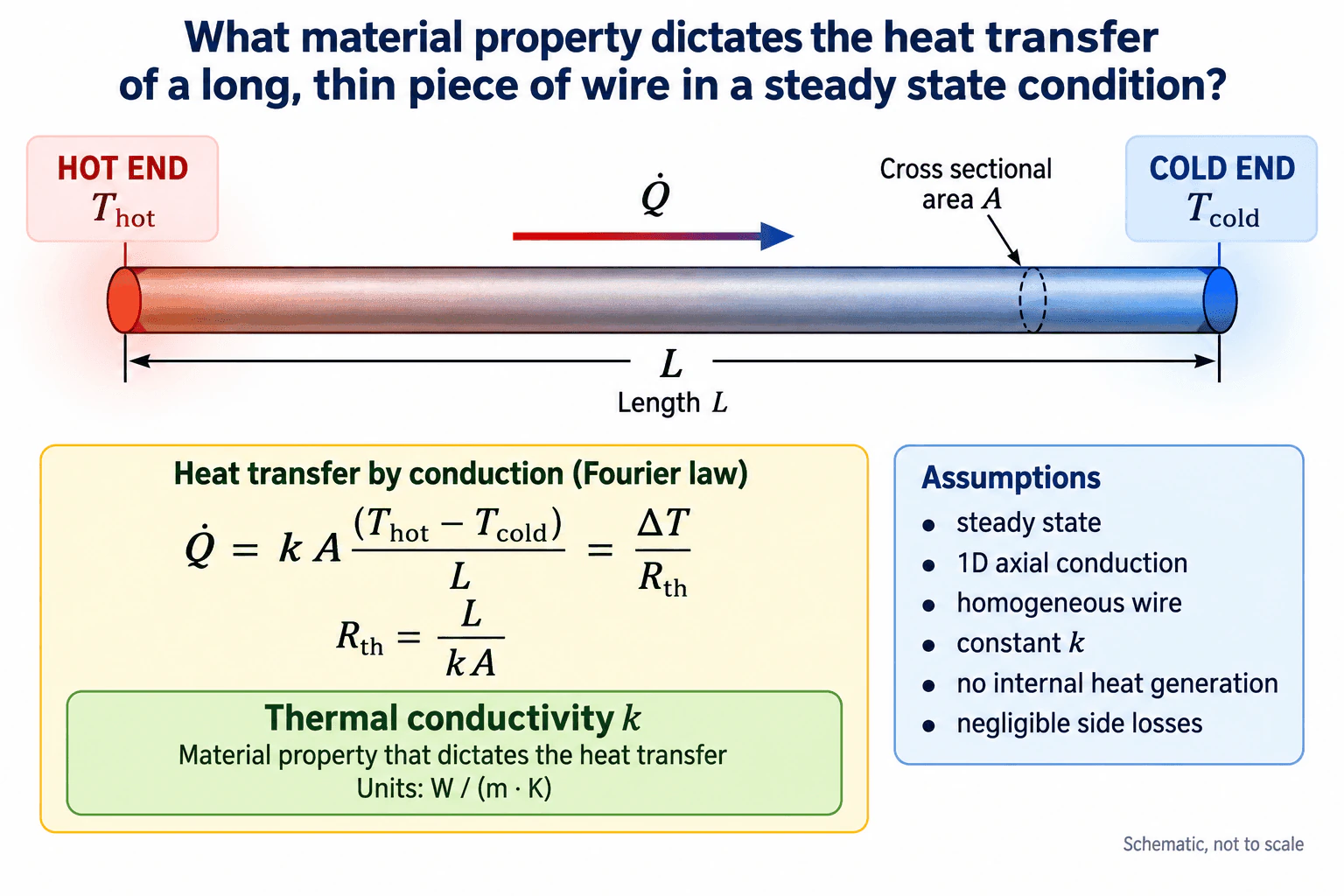
The key material property is thermal conductivity, k, measured in W/(m·K). For a long, thin, uniform wire under steady, one dimensional axial conduction, Fourier law gives Q̇ = kA(T_hot − T_cold)/L. Equivalently, R_th = L/(kA). Therefore, for the same length, cross sectional area, and end temperatures, a higher thermal conductivity gives a higher conductive heat transfer rate.
Detailed Explanation
Thermal conductivity, k, is the material property that controls how readily heat conducts through the wire. Model the wire as a uniform conduction path of length L and cross sectional area A, with a hot end at T_hot and a cold end at T_cold. Heat flows axially from the hot end toward the cold end.
For steady, one dimensional conduction with constant k, no internal heat generation, and negligible side heat losses, Fourier law becomes Q̇ = kA(T_hot − T_cold)/L. The same relationship can be written as Q̇ = ΔT/R_th, where R_th = L/(kA). Thermal conductivity is the intrinsic material property, while thermal resistance depends on both the material and the wire geometry.
Useful Questions to Ask the Interviewer
Should I assume the wire is homogeneous with constant thermal conductivity?
Can I assume one dimensional axial conduction with negligible side heat losses?
Are the end temperatures fixed with no internal heat generation?
How to Explain It in an Interview
Physical Method
I would define the wire length as L in meters, cross sectional area as A in square meters, hot end temperature as T_hot, and cold end temperature as T_cold. The heat transfer rate Q̇ is in watts, and heat flows from the higher temperature end toward the lower temperature end.
For steady, one dimensional conduction through a homogeneous wire with constant k, Fourier law gives Q̇ = kA(T_hot − T_cold)/L. Thermal conductivity k has units W/(m·K).
The same model can be written using thermal resistance. R_th = L/(kA), so Q̇ = ΔT/R_th. This shows that k is the material property, while the total resistance also depends on length and cross sectional area.
Engineering Reasoning
If L, A, T_hot, and T_cold stay fixed, increasing k increases Q̇ directly. A material with higher thermal conductivity therefore transfers more heat through the same wire under the same temperature difference.
The equation is dimensionally consistent because kAΔT/L has units of watts. The resistance form also gives units of K/W for R_th.
Assumptions And Checks
The simplified result assumes steady state, one dimensional axial conduction, a homogeneous wire, constant thermal conductivity, no internal heat generation, and negligible side heat losses. These are the same assumptions required by the idealized wire model.
If k varies strongly with temperature or the material is anisotropic, the simple constant k expression must be replaced by a more appropriate conduction model. For the stated ideal wire problem, the final answer is thermal conductivity, k.
Why Interviewers Ask This
This question tests whether the candidate can identify thermal conductivity as the governing material property and connect it correctly to Fourier conduction, wire geometry, temperature difference, heat flow direction, and thermal resistance.
Common interview mistakes
Common mistakes include naming thermal resistance instead of thermal conductivity as the material property, confusing conductivity with conductance, ignoring the effects of length and cross sectional area, reversing the heat flow direction, or using the constant k equation when conductivity varies significantly with temperature or direction.
Interview tip
State thermal conductivity first, then support it with Fourier law. Define k as the material property and contrast it with R_th = L/(kA), which depends on both the material and the wire geometry.
Interviewer may ask next
What assumptions are required for Q̇ = kA(T_hot − T_cold)/L to apply directly?
The assumptions are steady state, one dimensional axial conduction, a homogeneous wire, constant thermal conductivity, constant cross sectional area, no internal heat generation, and negligible side heat losses. If these assumptions do not hold, the conduction model must be modified.
What happens to the heat transfer rate if the wire length doubles while the material, area, and end temperatures stay unchanged?
The thermal resistance R_th = L/(kA) doubles. Because Q̇ = ΔT/R_th, the conductive heat transfer rate becomes one half of its original value.
2. What is the value of the convective heat transfer coefficient in natural convection?Convection And Fluid FlowMediumApple
Short Interview Answer (30-60 seconds)
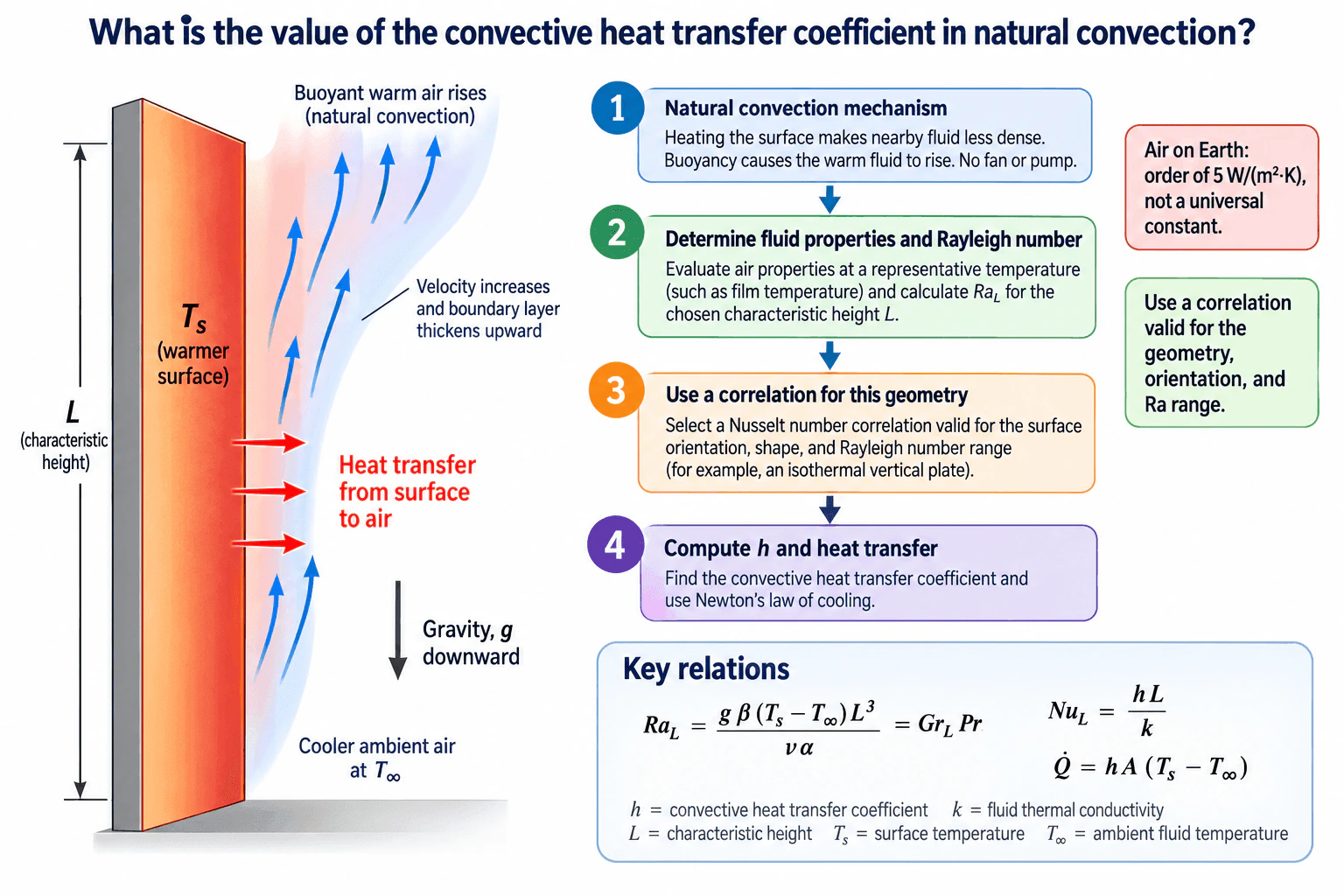
There is no single universal value for the convective heat transfer coefficient in natural convection. For natural convection in air, a value around 5 W/(m²·K) can be a reasonable rough estimate for some situations, but the actual value depends on the geometry and operating conditions. I would calculate the Rayleigh number, select a valid Nusselt number correlation, and then calculate h from NuL = hL/k.
Detailed Explanation
Natural convection occurs when temperature differences create density differences in a fluid and buoyancy causes the fluid to move without a fan or pump. Because that motion depends on the fluid, temperature difference, gravity, geometry, orientation, and characteristic length, the convective heat transfer coefficient h does not have one fixed value.
For the vertical warm surface represented in the diagram, cooler ambient air at T∞ is heated near the surface at Ts. The warmer fluid becomes less dense and rises. This creates a natural convection boundary layer that becomes thicker as the flow moves upward, while heat transfers from the surface into the surrounding air.
Useful Questions to Ask the Interviewer
What fluid and surface geometry should I assume?
What are the surface temperature Ts and ambient temperature T∞?
What characteristic length and surface orientation should I use?
How to Explain It in an Interview
I would first state that h is not a universal constant. For natural convection in air, a value around 5 W/(m²·K) can be used as a rough estimate in some cases, but the defensible value comes from a correlation for the actual configuration.
For a vertical surface, I would use the characteristic height L and evaluate the fluid properties at a representative temperature, commonly the film temperature when that assumption is appropriate. The governing dimensionless group is the Rayleigh number:
RaL = g β (Ts − T∞) L³/(ν α) = GrL Pr
Here, g is gravitational acceleration, β is the thermal expansion coefficient, ν is kinematic viscosity, α is thermal diffusivity, GrL is the Grashof number, and Pr is the Prandtl number.
I would then select a Nusselt number correlation that is documented for the surface geometry, orientation, boundary condition, and Rayleigh number range. Once NuL is known:
NuL = hL/k
Therefore:
h = NuL k/L
where k is the fluid thermal conductivity.
The corresponding convection heat transfer is:
Q̇ = hA(Ts − T∞)
I would finally verify that the calculated Rayleigh number is within the correlation validity range, that the property evaluation temperature is appropriate, and that the resulting h and heat transfer are physically reasonable. The key conclusion is that natural convection h must be tied to the specific fluid, geometry, temperatures, length scale, and applicable correlation rather than treated as a fixed property of air.
Why Interviewers Ask This
This question evaluates whether the candidate understands that the natural convection coefficient is not a universal material constant. The interviewer is looking for recognition that h depends on the fluid, geometry, orientation, characteristic length, temperature conditions, gravity, and the natural convection correlation that applies to the resulting Rayleigh number.
Common interview mistakes
Common mistakes include treating h as a fixed property of air, using a forced convection correlation for a natural convection problem, choosing a Nusselt correlation outside its valid geometry or Rayleigh number range, using an inappropriate characteristic length, evaluating fluid properties at an inconsistent temperature, and calculating heat transfer without clearly defining Ts, T∞, area, and the physical boundary.
Interview tip
Start with the key statement that natural convection h is not one universal value. Give about 5 W/(m²·K) only as a rough air estimate when appropriate, then explain the defensible calculation path: define the geometry and temperatures, evaluate fluid properties, calculate RaL, choose the applicable NuL correlation, and obtain h from NuL = hL/k.
Interviewer may ask next
How would you check whether your calculated natural convection coefficient is valid?
I would verify that the geometry, orientation, boundary condition, and Rayleigh number fall within the documented applicability range of the selected Nusselt correlation. I would also confirm that the fluid properties were evaluated at the intended representative temperature, check dimensional consistency, and compare the resulting coefficient and heat transfer with physically reasonable behavior for the stated conditions.
What happens to the convection coefficient if the temperature difference or characteristic length changes?
Changing the temperature difference or characteristic length changes the Rayleigh number, which changes the predicted Nusselt number and therefore h. The relationship is not generally a simple constant multiplier because the natural convection correlation relates NuL to RaL and Pr. I would recalculate RaL, confirm that the selected correlation remains valid, and then recompute h = NuL k/L.
3. Imagine a MacBook is a black box with a single inlet and exhaust. How much CFM is required to cool 100W of power?Convection And Fluid FlowHardApple
Short Interview Answer (30-60 seconds)
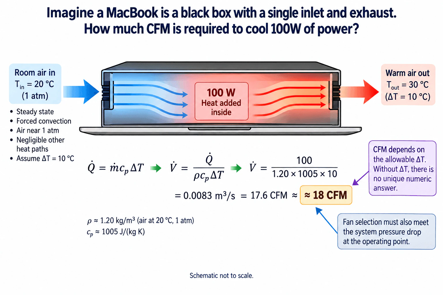
There is no unique CFM value from 100 W alone because the allowable air temperature rise must also be specified. If I assume steady forced convection, inlet air at 20 °C and about 1 atm, outlet air at 30 °C, negligible other heat paths, and therefore ΔT = 10 °C, then Q̇ = ρ V̇ cp ΔT. Using ρ ≈ 1.20 kg/m³ and cp ≈ 1005 J/(kg K), V̇ ≈ 0.0083 m³/s, which is about 17.6 CFM. I would report approximately 18 CFM for those assumptions, then verify that the fan can provide that flow at the system pressure drop.
Detailed Explanation
Treat the MacBook as one control volume with a single air inlet, a single exhaust, and 100 W of heat transferred to the airflow. This is an internal forced convection problem. The important missing input is the allowable air temperature rise, so there is no unique CFM answer until ΔT is specified.
Useful Questions to Ask the Interviewer
What air temperature rise between the inlet and exhaust should I allow?
Can I assume all 100 W is removed by the airflow, with other heat paths neglected?
Should I calculate the ideal airflow only, or also discuss the fan operating point and system pressure drop?
How to Explain It in an Interview
Assume steady state operation, forced convection, inlet air at 20 °C and about 1 atm, outlet air at 30 °C, and negligible other heat paths. The allowable air temperature rise is therefore ΔT = 10 °C.
For sensible heating of the air,
Q̇ = ṁ cp ΔT
The mass flow rate is related to volumetric flow by
ṁ = ρ V̇
Combining them gives
V̇ = Q̇ / (ρ cp ΔT)
Using Q̇ = 100 W, ρ ≈ 1.20 kg/m³, cp ≈ 1005 J/(kg K), and ΔT = 10 K,
V̇ = 100 / (1.20 × 1005 × 10)
V̇ ≈ 0.0083 m³/s
That is approximately 17.6 CFM, so the interview answer is about 18 CFM for the stated assumptions.
The key point is that CFM depends directly on the chosen allowable temperature rise. A smaller ΔT requires more airflow, while a larger ΔT requires less airflow. This energy balance gives the thermal airflow requirement only. The actual fan must also deliver the required airflow at the system pressure drop and its resulting operating point.
For validation, I would measure inlet temperature, exhaust temperature, airflow, heat dissipation, and system pressure drop under representative operating conditions. If other heat paths are significant or the measured temperature rise differs from the assumption, I would update the energy balance.
Why Interviewers Ask This
This tests whether the candidate can define a thermal control volume, recognize that the required airflow depends on the allowable air temperature rise, apply a steady forced convection energy balance, keep units consistent, state assumptions explicitly, and distinguish an ideal airflow requirement from the fan operating point required in real hardware.
Common interview mistakes
Common mistakes include giving one CFM value without stating an allowable temperature rise, forgetting air density when converting mass flow to volumetric flow, mixing inconsistent unit systems, using temperature values instead of the temperature difference, assuming the fan will deliver its free airflow rating inside the product, and ignoring the system pressure drop that determines the actual operating point.
Interview tip
Start by stating that 100 W alone does not determine CFM. Define the allowable ΔT, show the steady energy balance, calculate the airflow with consistent units, and finish by noting that the selected fan must supply that flow at the system pressure drop.
Interviewer may ask next
How would you validate the approximately 18 CFM estimate in real hardware?
I would measure inlet temperature, exhaust temperature, actual airflow, heat dissipation, component temperatures, and system pressure drop while operating near the 100 W condition. I would compare the measured air temperature rise and airflow with the energy balance. If significant heat leaves through other paths or the measured ΔT differs from 10 °C, I would revise the model and required airflow.
What happens if the allowable air temperature rise is only 5 °C instead of 10 °C?
From V̇ = Q̇ / (ρ cp ΔT), the required volumetric flow is inversely proportional to ΔT when the other assumptions remain the same. Halving ΔT from 10 °C to 5 °C approximately doubles the required airflow from about 17.6 CFM to about 35.2 CFM. The higher flow would also require a different fan operating point and generally a greater pressure and acoustic burden.
4. What is the value of emissivity for Apple product casings?Radiation Heat TransferMediumApple
Short Interview Answer (30-60 seconds)
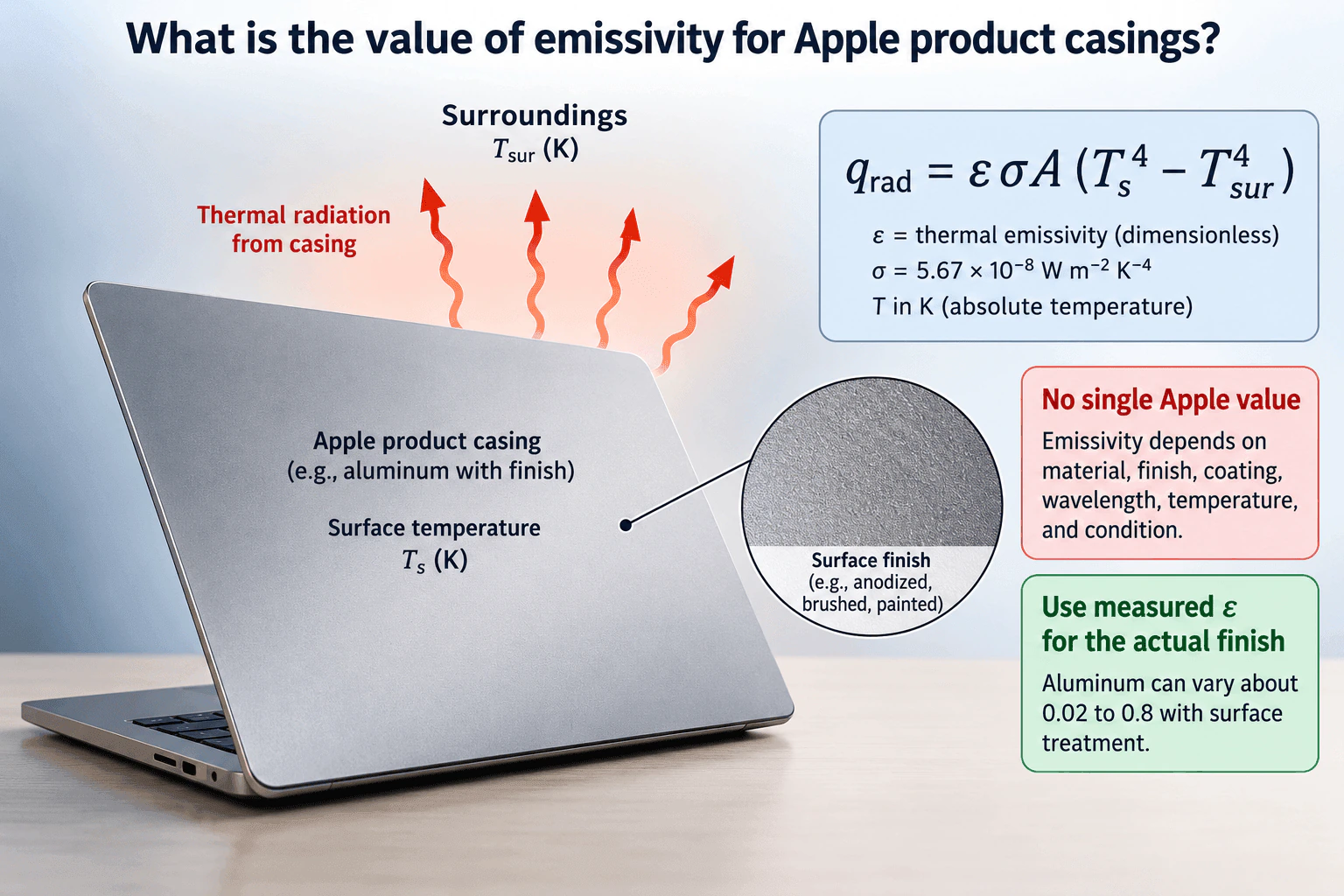
There is no single emissivity value for all Apple product casings. Emissivity depends strongly on the actual material and surface finish, including anodizing, paint, oxidation, texture, coating, wavelength range, temperature, and condition. For aluminum surfaces, values can vary roughly from 0.02 to 0.8 depending on treatment. For a real thermal model, I would use measured emissivity for the actual finished casing whenever possible and use absolute temperature in kelvin in the radiation calculation.
Detailed Explanation
Emissivity, ε, describes how effectively a real surface emits thermal radiation compared with an ideal blackbody at the same temperature. It is dimensionless and ranges from 0 to 1. The key point is that emissivity is controlled by the actual surface, not simply by the word aluminum. A polished metallic surface can have low emissivity, while anodizing, paint, oxidation, texture, or another coating can increase it substantially.
The diagram therefore does not assign one universal number to an Apple casing. It shows an approximate aluminum range of 0.02 to 0.8 to illustrate how strongly surface treatment can affect radiation behavior. That range is not an Apple product specification. The engineering value should come from the actual finished surface under the relevant operating conditions.
Useful Questions to Ask the Interviewer
What casing material and surface finish should I assume?
What surface temperature and surrounding temperature should I use?
Are we modeling radiation to large surroundings, or a more specific enclosure geometry with view factors?
How to Explain It in an Interview
Start by defining the physical boundary. Let the casing surface be at Ts in kelvin and the surroundings be at Tsur in kelvin. For the simple case shown in the diagram, assume the surface behaves approximately as a diffuse gray surface exchanging radiation with large isothermal surroundings that it effectively sees completely.
The net radiation heat transfer is
qrad = ε σ A (Ts^4 − Tsur^4)
where ε is thermal emissivity, σ is the Stefan Boltzmann constant, approximately 5.67 × 10^−8 W m^−2 K^−4, A is radiating area, and both temperatures are absolute temperatures in kelvin.
I would not select ε from the base material name alone. I would identify the finished external surface, including anodizing, brushing, paint, oxidation, texture, or coating. The diagram shows why this matters because aluminum surfaces can span roughly 0.02 to 0.8 depending on treatment. That range is illustrative and should not be treated as an Apple specification.
If measured data for the actual casing finish are available, I would use those data. Otherwise, I would choose a defensible literature value for the closest matching surface and perform a sensitivity check over the plausible range.
Emissivity should not be confused with absorptivity or reflectivity. They are related radiative properties but are not interchangeable constants. Under thermal equilibrium, spectral emissivity and spectral absorptivity are related by Kirchhoff's law for corresponding wavelength and direction.
If the geometry is more complex than a surface facing large surroundings, I would include view factors and check enclosure reciprocity and summation relationships. The final ε should therefore come from the actual surface specification or measurement rather than an assumed universal Apple casing value.
Why Interviewers Ask This
This question tests whether the candidate understands that emissivity is a surface property rather than one universal constant for a material or product family. It also tests whether the candidate can select a defensible value for radiation heat transfer using the actual casing material, finish, coating, wavelength range, temperature, and surface condition.
Common interview mistakes
Common mistakes include assigning one emissivity value to every aluminum surface, treating a literature range as an Apple product specification, using Celsius directly in the fourth power radiation equation, confusing emissivity with absorptivity or reflectivity, and ignoring surface finish, wavelength dependence, temperature, condition, or geometric visibility.
Interview tip
Lead with the main judgment: there is no single Apple casing emissivity. Then explain that the actual finished surface determines the appropriate value, state the radiation equation using kelvin, and say that measured emissivity for the real finish is preferable to a generic material value.
Interviewer may ask next
How would you validate the emissivity value used in the thermal model?
I would identify the exact casing material, finish, coating, temperature range, and relevant wavelength range. I would compare the selected value with data for a closely matching surface and, when possible, measure the actual finished part using an appropriate emissivity measurement method. I would then vary ε over a plausible range and check how sensitive the predicted radiation heat transfer or casing temperature is to that uncertainty.
What changes if the casing is painted or anodized instead of being a polished metallic surface?
The emissivity can increase substantially because the outer surface treatment changes its radiative behavior. I would replace the polished metal value with data for the actual paint or anodized finish. In the same Stefan Boltzmann relation, a larger ε increases the magnitude of net radiation exchange for the same area and temperatures, so radiation can become a more important part of the casing energy balance.
5. What is a thermocouple and how does it work?Thermal Testing And ValidationEasyApple
Short Interview Answer (30-60 seconds)
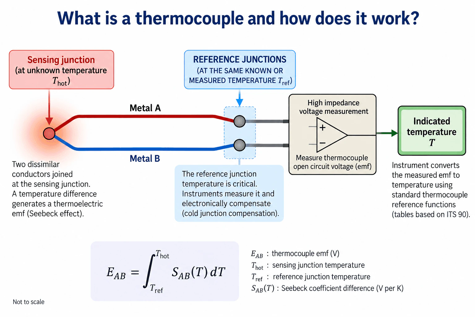
A thermocouple is a temperature sensor made from two dissimilar conductors joined at a sensing junction. When the sensing junction and the reference junctions are at different temperatures, temperature gradients in the two conductors create a thermoelectric voltage through the Seebeck effect. A high impedance instrument measures that voltage, measures or otherwise knows the common reference junction temperature, applies cold junction compensation, and uses the appropriate thermocouple reference function to determine the sensing junction temperature.
Detailed Explanation
A thermocouple measures temperature by relating a thermoelectric voltage to the temperature difference between its sensing junction and its reference junctions. Two dissimilar conductors, Metal A and Metal B, are joined at the sensing junction at temperature T_hot. At the instrument end, the two conductors remain electrically separate and each transitions to a measurement lead at a reference junction. Both reference junctions are kept at the same known or measured temperature T_ref. The instrument measures the open circuit voltage between the two thermocouple legs.
Useful Questions to Ask the Interviewer
Are you asking only about the basic operating principle, or should I also discuss practical measurement errors such as placement and calibration?
Should I assume the reference junction temperature is measured electronically for cold junction compensation?
Is there a specific thermocouple type or temperature range you want me to consider?
How to Explain It in an Interview
Physical Method
The key principle is the Seebeck effect. The thermoelectric response of the two conductors is different, so a temperature difference creates a measurable emf. For the conductor pair, the voltage can be represented as E_AB = integral from T_ref to T_hot of S_AB(T) dT, where E_AB is thermocouple emf in volts and S_AB(T) is the difference between the Seebeck coefficients of the two conductors in volts per kelvin.
The two conductors are joined together only at the sensing junction. At the instrument end, each thermocouple conductor has its own separate reference connection. Those two reference connections should be at the same measured temperature so the instrument can account for their contribution. A high impedance input measures the voltage while drawing negligible current.
The instrument measures E_AB and T_ref, applies cold junction compensation, and uses the reference function or table for the selected thermocouple type to infer T_hot. Standard thermocouple reference functions are commonly based on ITS 90.
Assumptions And Checks
I would confirm the thermocouple type, polarity, reference junction measurement, calibration status, expected temperature range, and sensor placement. I would also consider thermal contact, heat conduction along the wires, electrical noise, connector materials, and acquisition accuracy because these effects can bias the result.
For validation, I would compare the measurement with an independent calibrated reference where practical and include thermocouple calibration, reference junction sensing, data acquisition accuracy, repeatability, and placement effects in the uncertainty assessment.
Engineering Reasoning
A thermocouple fundamentally responds to a temperature difference rather than measuring absolute temperature directly. Knowing T_ref is therefore essential. Cold junction compensation combines the measured thermoelectric voltage with the measured reference temperature to determine the sensing junction temperature. Agreement at one condition does not by itself validate the installation across all temperatures, environments, or transient operating cases.
Why Interviewers Ask This
The interviewer is checking whether I understand the physical principle behind a common temperature sensor, the role of the reference junction temperature, and the practical measurement issues that affect thermal test accuracy.
Common interview mistakes
Common mistakes include saying that a thermocouple directly measures absolute temperature, ignoring the reference junction temperature, drawing the two thermocouple legs electrically joined at the instrument end, reversing polarity, using the wrong thermocouple reference function, assuming wire color alone proves the material type, and ignoring errors from poor thermal contact, heat conduction through the wires, electrical noise, calibration uncertainty, or reference junction sensing.
Interview tip
Start with the two dissimilar conductors and the Seebeck effect, then explain the sensing junction, the two separate reference connections at T_ref, voltage measurement, cold junction compensation, and conversion from emf to temperature. Mentioning measurement uncertainty and sensor placement shows practical thermal test understanding without overcomplicating the basic answer.
Interviewer may ask next
How would you validate that a thermocouple measurement is trustworthy?
I would verify the thermocouple type and polarity, confirm calibration traceability where required, check that the data acquisition system uses the correct reference function, verify the reference junction temperature measurement, and inspect sensor attachment and wire routing. I would compare the reading with an independent calibrated reference at representative conditions and repeat measurements to evaluate consistency. The uncertainty assessment should include sensor calibration, reference junction measurement, acquisition accuracy, repeatability, thermal contact, and placement effects. Agreement at one operating point should not be treated as validation across the entire operating range.
What changes if the reference junction temperature varies during a test?
The thermocouple voltage depends on both the sensing junction temperature and the reference junction temperature, so a varying T_ref must be measured and compensated at an appropriate acquisition rate. The instrument uses the measured T_ref with the thermocouple reference function to account for the reference contribution before determining T_hot. If the reference junction sensor is inaccurate, poorly located, or not in thermal equilibrium with both terminal connections, that error propagates into the reported temperature.
Thermal Engineer Resume Examples
Explore the resume examples below to find the one that best matches your target Thermal Engineer role.
Disclaimer: This interview guide is for educational and informational purposes only. It is designed to help readers prepare, but it does not guarantee any interview result, hiring decision, offer, or outcome. Interview questions, hiring criteria, and preferred answers can vary by employer, interviewer, industry, location, and time. All answers, examples, and explanations in this guide are suggested examples for interview preparation, not definitive answers or instructions for professional practice. They are based on research and judgment, are provided without warranties of any kind, and should be adapted to the question, role, and applicable laws and professional requirements. Diagrams are simplified illustrations intended to highlight the main concepts and their relationships; actual situations, systems, and practices may be more complex. Alternative approaches may be equally valid or better suited to a particular question, context, or interviewer. To the fullest extent permitted by applicable law, the contributors and publisher are not liable for decisions made, actions taken, or losses incurred based on this guide.
State Laws and Professional Responsibilities: Laws and requirements governing an occupation vary by state and jurisdiction. You are responsible for checking the current laws, licensing requirements, and scope-of-practice rules that apply to your location and role, and for ensuring that your answers and actions comply with them. Adapt examples in this guide to those requirements. This guide is not legal advice.
Company Notice: This guide is an independent educational resource and is not affiliated with, endorsed by, sponsored by, or approved by the company named in this guide. Company names identify reported interview experiences or the employer context of clearly labeled original practice exercises. Interview practices can change without notice, and inclusion of company-specific content does not mean these questions are official, complete, or guaranteed to be asked. To the fullest extent permitted by law, the author, contributors, and publisher are not responsible for outcomes related to use of this material.
Content Accuracy and Verification: To the fullest extent permitted by applicable law, we do not represent or warrant that interview guides, questions, answers, examples, or diagrams are accurate, complete, current, error-free, or suitable for any particular purpose. You are responsible for independently reviewing and verifying the information before relying on it.