1. Why might tightening a wire supporting a heavy picture make the wire snap?
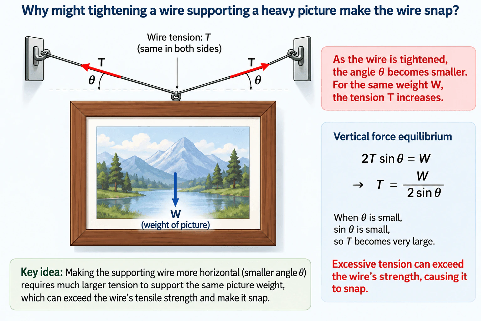
A tighter supporting wire usually becomes more horizontal. The picture still has the same weight, so the vertical components of the two wire tensions must still support that weight. If θ is measured from the horizontal, vertical equilibrium gives 2T sin θ = W, or T = W / (2 sin θ). As θ gets smaller, sin θ gets smaller, so the wire tension becomes much larger. That increased tension can exceed the wire's tensile capacity and make it snap.
The key idea is that tightening the wire changes its geometry, even though the picture's weight stays the same. Assume the picture is stationary, the two wire segments are symmetric, and each segment carries the same tension T. Let W be the picture's weight and let θ be the angle each wire segment makes with the horizontal.
For static equilibrium, the horizontal tension components cancel because of symmetry. Each wire contributes an upward component T sin θ, so vertical force equilibrium is:
2T sin θ = W
Solving for the wire tension gives:
T = W / (2 sin θ)
This equation explains why tightening can cause failure. As the wire becomes more nearly horizontal, θ decreases. Then sin θ also decreases, so T must increase to provide the same total upward force W. In the limiting case as θ approaches 0°, sin θ approaches zero, so the idealized equation predicts a very large required tension.
A real wire has finite tensile capacity. If the required tension becomes greater than what the wire or its attachment can safely carry, the wire can yield or fracture. The equilibrium equation determines the tension required by the load and geometry; actual failure depends on the wire's material, cross-sectional area, condition, and connections.
- Should I assume the wire arrangement is symmetric and the picture is in static equilibrium?
- Is θ defined as the angle of each wire segment from the horizontal?
- Should I explain only the force balance, or also discuss tensile stress and failure capacity?
- Should the supports and attachment points be treated as ideal?
Start by defining the free body: the picture has weight W acting downward, and the two wire segments exert tensions T along the wires. State that the setup is symmetric and static. Resolve each wire tension vertically, giving T sin θ. The two vertical components must support the picture, so 2T sin θ = W. Rearranging gives T = W / (2 sin θ). Then explain the physical result: tightening makes the wire more horizontal, which reduces θ and increases the required tension. If that tension becomes greater than the wire's tensile capacity, the wire can snap. Before applying the simplified model to a real installation, verify the actual geometry, wire properties, cross-sectional area, attachment condition, and appropriate design margin.
- Define the free-body boundary around the picture and its supporting connection.
- Assume static equilibrium and, for the basic model, two symmetric wire segments carrying equal tension T.
- Define W as the picture's weight and θ as each wire segment's angle from the horizontal.
- Resolve each tension into horizontal and vertical components.
- Use symmetry to show that the horizontal components cancel.
- Apply vertical equilibrium: 2T sin θ = W.
- Solve for tension: T = W / (2 sin θ).
- Evaluate the limiting behavior as θ decreases: sin θ decreases and T increases.
- Compare the required tension with the real wire and connection capacity before making any safety conclusion.
The main tradeoff is geometric. Making the wire more horizontal reduces visible sag, but it sharply increases the tension needed to support the same picture weight. A steeper wire angle reduces the required tension. The simplified model assumes static, symmetric loading and does not include effects such as impact loading, fatigue, damaged wire, weak attachments, or unequal load sharing.
This tests whether the candidate can construct a simple free-body model, resolve inclined forces into components, apply static equilibrium, interpret a limiting case, and connect calculated tension to a realistic tensile failure mode.
Common mistakes are assuming each wire tension is simply W/2, forgetting that only the vertical component T sin θ supports the weight, measuring θ from the wrong reference direction, using cosine when θ is defined from the horizontal, confusing required tension with material strength, and assuming that a simplified equilibrium calculation alone proves a real installation is safe.
Define θ explicitly from the horizontal and write 2T sin θ = W before discussing failure. Then use the limiting case θ → 0° to explain the physics clearly: a nearly horizontal wire needs extremely large tension to provide enough vertical support.