This interview guide is for educational and informational purposes only. It is designed to help readers prepare, but it does not guarantee any interview result, hiring decision, offer, or outcome. Interview questions, hiring criteria, and preferred answers can vary by employer, interviewer, industry, location, and time. All answers, examples, and explanations in this guide are suggested examples for interview preparation, not definitive answers or instructions for professional practice. They are based on research and judgment, are provided without warranties of any kind, and should be adapted to the question, role, and applicable laws and professional requirements. Diagrams are simplified illustrations intended to highlight the main concepts and their relationships; actual situations, systems, and practices may be more complex. Alternative approaches may be equally valid or better suited to a particular question, context, or interviewer. To the fullest extent permitted by applicable law, the contributors and publisher are not liable for decisions made, actions taken, or losses incurred based on this guide.
State Laws and Professional Responsibilities
Laws and requirements governing an occupation vary by state and jurisdiction. You are responsible for checking the current laws, licensing requirements, and scope-of-practice rules that apply to your location and role, and for ensuring that your answers and actions comply with them. Adapt examples in this guide to those requirements. This guide is not legal advice.
Identity, Image, and Privacy Notice
To respect individual privacy, some names, profile photographs, avatars, biographical details, and other identifying information displayed in this guide may be replaced with pseudonyms, licensed stock images, illustrative avatars, composite images, or representative descriptions. Unless a person is expressly identified as an actual contributor, a displayed name, image, or profile should not be understood as depicting or identifying a specific candidate, interviewer, employee, or other real individual. These representations are provided for editorial and illustrative purposes only and do not imply endorsement, employment, participation, or affiliation with this guide or any company mentioned in it. Any resemblance to an actual person is coincidental.
Company Notice
This guide is an independent educational resource and is not affiliated with, endorsed by, sponsored by, or approved by the company named in this guide. Company names identify reported interview experiences or the employer context of clearly labeled original practice exercises. Interview practices can change without notice, and inclusion of company-specific content does not mean these questions are official, complete, or guaranteed to be asked. To the fullest extent permitted by law, the author, contributors, and publisher are not responsible for outcomes related to use of this material.
Content Accuracy and Verification
To the fullest extent permitted by applicable law, we do not represent or warrant that interview guides, questions, answers, examples, or diagrams are accurate, complete, current, error-free, or suitable for any particular purpose. You are responsible for independently reviewing and verifying the information before relying on it.
Questions or comments?
Contact us for general questions, or share feedback, technical corrections, and comments with the community.
1. Draw a standard temperature–entropy diagram for a refrigeration cycle.NEWThermodynamics And Heat TransferMediumTrane Technologies
Short Interview Answer (30-60 seconds)
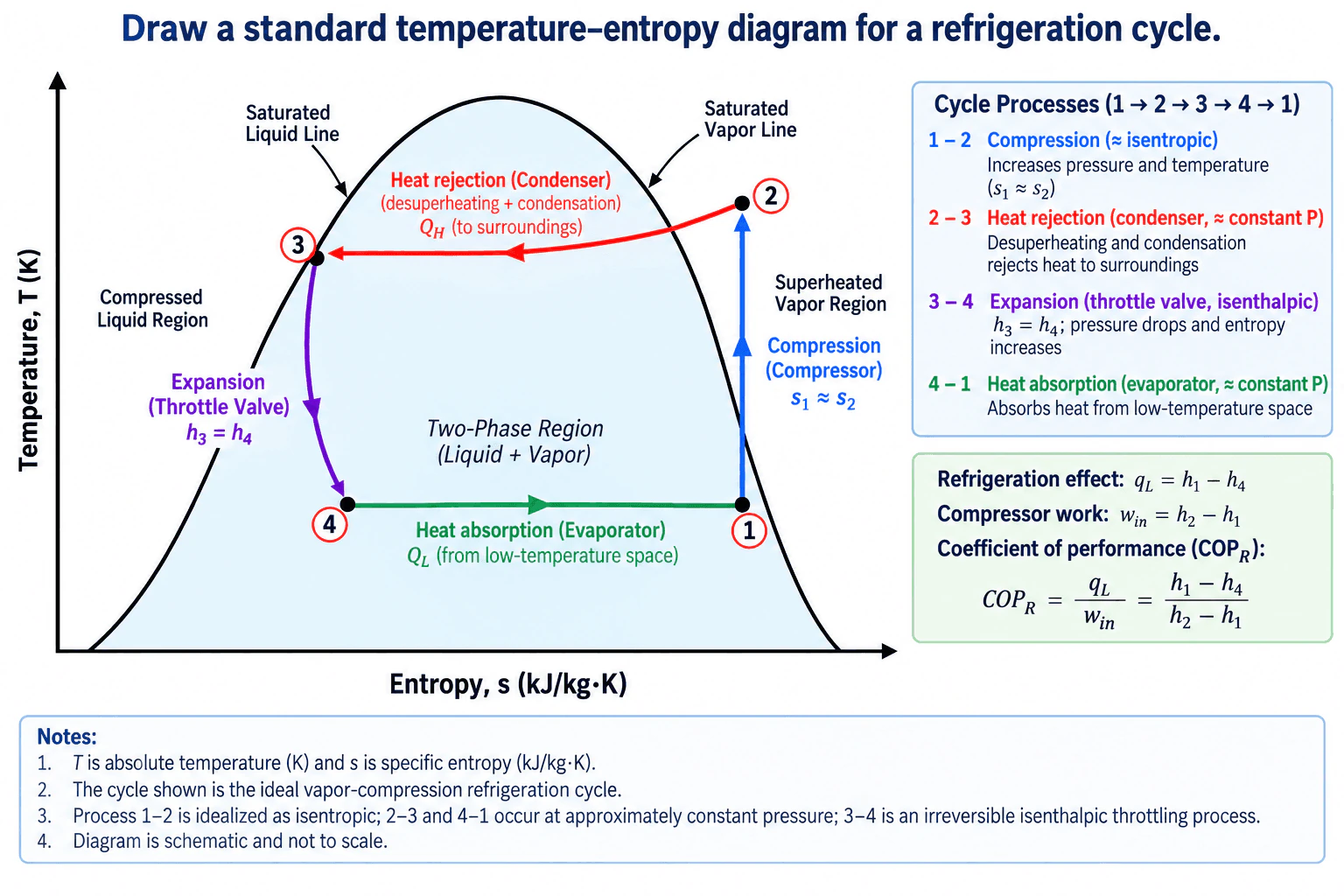
For a standard ideal vapor-compression refrigeration cycle, draw temperature T on the vertical axis and specific entropy s on the horizontal axis, then add the saturation dome. State 1 is low-pressure saturated vapor at the evaporator exit. Process 1→2 is ideal isentropic compression, so the path is approximately vertical on the schematic and ends as high-pressure superheated vapor. Process 2→3 is constant-pressure heat rejection in the condenser, including desuperheating and condensation to saturated liquid. Process 3→4 is irreversible throttling through the expansion valve with h3 = h4 and increasing entropy. Process 4→1 is approximately constant-pressure evaporation through the two-phase region back to saturated vapor.
Detailed Explanation
A standard temperature–entropy diagram for a refrigeration cycle is normally drawn for the ideal vapor-compression refrigeration cycle. Put absolute temperature T in kelvin on the vertical axis and specific entropy s in kJ/(kg·K) on the horizontal axis. Draw the saturation dome, with the saturated-liquid line on the left, saturated-vapor line on the right, the liquid–vapor two-phase region inside the dome, the compressed-liquid region to the left, and the superheated-vapor region to the right.
Use four states and follow the cycle 1→2→3→4→1.
State 1 is the evaporator exit and compressor inlet. For the standard saturated cycle shown, it is saturated vapor at low pressure.
Process 1→2 is compression in the compressor. In the ideal model it is adiabatic and reversible, so s1 = s2. On a schematic T–s diagram the path is drawn approximately vertical, consistent with the diagram label s1 ≈ s2. Pressure and temperature increase, and state 2 lies in the high-pressure superheated-vapor region. With negligible kinetic and potential energy changes, the specific compressor work input is w_in = h2 - h1.
Process 2→3 is heat rejection in the condenser at approximately constant high pressure. The superheated refrigerant first desuperheats, then reaches the saturated-vapor line and condenses through the two-phase region. In the standard saturated cycle, state 3 is saturated liquid. The condenser heat rejected per unit mass is q_H = h2 - h3 when q_H is treated as a positive magnitude.
Process 3→4 is expansion through the throttling valve. The valve is modeled as adiabatic with no shaft work and negligible kinetic and potential energy changes, so the process is isenthalpic: h3 = h4. Throttling is irreversible, so entropy increases. State 4 therefore lies to the right of state 3 and inside the low-pressure two-phase region as a liquid–vapor mixture.
Process 4→1 is heat absorption in the evaporator at approximately constant low pressure. The liquid–vapor mixture absorbs heat from the low-temperature space and evaporates until it reaches saturated vapor at state 1. The refrigeration effect is q_L = h1 - h4.
The coefficient of performance for the ideal refrigeration cycle is COP_R = q_L / w_in = (h1 - h4) / (h2 - h1). COP is not a thermal efficiency; it is the useful refrigeration effect divided by compressor work input and can be greater than 1.
Using positive magnitudes for refrigeration effect, compressor work input, and condenser heat rejection, the steady-cycle first-law balance is q_H = q_L + w_in.
The standard assumptions are steady-state operation, negligible kinetic and potential energy changes, negligible pressure drops through the condenser and evaporator, ideal isentropic compression for the reference cycle, isenthalpic throttling, and no unintended heat transfer from the compressor or expansion device unless otherwise stated. The T–s drawing is schematic and not to scale.
Useful Questions to Ask the Interviewer
Do you want the standard ideal saturated vapor-compression cycle, or should I include real effects such as compressor inefficiency, superheat, subcooling, and pressure losses?
Is a particular refrigerant assumed? The exact saturation-dome shape and property values depend on the working fluid.
Should the diagram remain qualitative, or do you want numerical temperatures, pressures, enthalpies, or entropy values? Without a specified refrigerant and operating conditions, I would keep it qualitative.
How to Explain It in an Interview
I would explain the diagram by following the four physical components in operating order: compressor, condenser, expansion valve, and evaporator. Compression 1→2 is idealized as isentropic, so it is drawn approximately vertical. Condenser heat rejection 2→3 starts in the superheated region, includes desuperheating, then continues through condensation to saturated liquid. Throttling 3→4 is not isentropic; it is an irreversible constant-enthalpy pressure drop, so h3 = h4 while entropy increases and the refrigerant enters the two-phase region. Evaporation 4→1 occurs at approximately constant low pressure as the refrigerant absorbs heat and returns to saturated vapor. I would finish by checking that the state locations are physically consistent, h3 = h4 across the valve, s1 = s2 for the ideal compressor model, and q_H = q_L + w_in for the complete steady cycle.
Technical Approach
1. Define the system as the standard ideal single-stage vapor-compression refrigeration cycle operating at steady state. 2. Draw T on the vertical axis and specific entropy s on the horizontal axis, then add the saturation dome and label the compressed-liquid, two-phase, and superheated-vapor regions. 3. Place state 1 on the saturated-vapor line at the low evaporator pressure. 4. Draw 1→2 approximately vertically upward to represent ideal isentropic compression, with s1 = s2 in the ideal model, ending in the high-pressure superheated region. 5. Draw 2→3 along the high-pressure condenser process, showing desuperheating followed by condensation to saturated liquid at state 3. 6. Draw 3→4 downward and to the right through the expansion valve, with h3 = h4 and entropy increasing, ending as a low-pressure liquid–vapor mixture. 7. Draw 4→1 through the two-phase region at approximately constant low pressure to represent evaporation and heat absorption. 8. Relate the cycle to q_L = h1 - h4, w_in = h2 - h1, q_H = h2 - h3, and COP_R = (h1 - h4)/(h2 - h1). 9. Check that the steady-cycle energy balance q_H = q_L + w_in is satisfied when all three quantities are treated as positive magnitudes, and confirm that every state lies in the correct phase region.
Practical Insights
The main tradeoff is model fidelity rather than computational complexity. The ideal T–s cycle is useful for explaining the refrigeration process and estimating theoretical performance, but real systems include compressor inefficiency, superheating, subcooling, pressure drops, heat leakage, and other non-ideal effects. Adding those effects gives a more realistic result but requires refrigerant property data and additional state calculations. A higher evaporator temperature generally reduces the required compression lift and can improve COP, while a higher condensing temperature generally increases compressor work and reduces COP. Liquid subcooling can increase the refrigeration effect, while real compressor irreversibility increases entropy generation and required work.
Why Interviewers Ask This
Interviewers use this question to check whether you understand the standard vapor-compression refrigeration cycle, can place the four thermodynamic states correctly on a temperature–entropy diagram, and can distinguish isentropic compression, constant-pressure heat rejection and evaporation, and irreversible isenthalpic throttling. They also want to see whether you understand how entropy, enthalpy, phase change, compressor work, refrigeration effect, and coefficient of performance relate to the physical refrigeration system.
Common interview mistakes
Common mistakes are drawing the expansion process as isentropic instead of isenthalpic, drawing 3→4 vertically as though entropy were constant, placing state 4 outside the two-phase region, reversing the direction of the condenser or evaporator processes, omitting the desuperheating portion of 2→3, confusing COP with thermal efficiency, or assigning numerical properties when no refrigerant or operating conditions have been supplied. Another mistake is forgetting that throttling is irreversible: enthalpy remains approximately constant while entropy increases.
Interview tip
Tie each process to a physical component rather than memorizing the curve shape: compressor = ideal isentropic 1→2, condenser = high-pressure heat rejection 2→3, expansion valve = irreversible isenthalpic 3→4, and evaporator = low-pressure heat absorption 4→1. Explicitly stating h3 = h4 and that ideal compression has s1 = s2 shows that you understand the two processes candidates most often confuse.
Interviewer may ask next
How would the T–s diagram change for a real compressor instead of an ideal isentropic compressor?
A real compressor is irreversible, so entropy increases during compression. Instead of following the ideal approximately vertical 1→2 path with s2 = s1, the actual outlet state lies to the right of the ideal outlet at the same discharge pressure, with s2,actual > s1. The actual outlet enthalpy and compressor work are also higher than for the isentropic reference process. Compressor isentropic efficiency is commonly written as η_c = (h2s - h1)/(h2 - h1), where h2s is the outlet enthalpy for isentropic compression to the same discharge pressure and h2 is the actual outlet enthalpy.
What happens to the refrigeration cycle if the condenser provides liquid subcooling before the expansion valve?
With liquid subcooling, state 3 moves from the saturated-liquid line into the compressed-liquid region at approximately the same condenser pressure. The expansion valve still satisfies h3 = h4, but the lower state-3 enthalpy also lowers state-4 enthalpy. If state 1 remains unchanged, the refrigeration effect q_L = h1 - h4 increases. This often improves cycle COP because the useful refrigeration effect increases without directly increasing the ideal compressor work for unchanged compressor inlet and discharge states.
2. Tell me about a time you had to solve a problem amongst a team of peers.NEWBehavioralMediumTrane Technologies
i Question Details
You had limited direction from superiors.
Interview tip:
Use STAR to structure your answer: briefly explain the Situation and Task, make Action the most detailed part, and finish with the Result. For example, describe a project where a team of peers had different views on the cause of a mechanical problem, senior leaders gave limited direction, and you helped the team use evidence, communication, and practical testing to agree on a solution.
Situation
During a previous project, I was working with a team of engineers to investigate excessive vibration in a mechanical assembly during testing. We had limited direction from our supervisors because they expected the engineering team to work through the issue. Several team members had different opinions about the cause. Some thought the problem came from component alignment, while others believed the mounting arrangement was creating the vibration.
Task
My responsibility was to help the team identify the actual cause and agree on a practical solution without turning the technical disagreement into a personal conflict. We also needed to keep the testing work moving while making sure any change was supported by evidence.
Action
I suggested that we first separate our assumptions from what we could measure. I asked each person to explain what evidence supported their view, and I wrote the possible causes in a simple list. We then agreed on checks that could eliminate one cause at a time. I reviewed the assembly drawings and tolerances, inspected the alignment with the team, and compared the condition before and after controlled adjustments. I also suggested checking the mounting points because their stiffness could affect how vibration moved through the assembly. During the discussion, I made sure everyone had a chance to explain their reasoning instead of trying to prove one person right. As the test results came in, we updated our list of possible causes. The evidence showed that alignment was acceptable, while the mounting condition was contributing significantly to the vibration. I worked with the team to modify the mounting arrangement and repeat the test. We documented what we changed and why so that the decision was clear to everyone.
Result
The revised mounting arrangement reduced the vibration and allowed the team to continue testing with more confidence. More importantly, the team reached the solution together instead of relying on authority or opinion. I learned that when peers disagree and leadership gives limited direction, a good way forward is to create a shared fact based process, listen carefully, and let evidence guide the decision.
Why Interviewers Ask This
Interviewers ask this question to understand how a candidate works through disagreement when there is little management direction. A strong answer shows that the candidate can communicate with peers, use sound engineering judgment, create structure when the path is unclear, and help a team reach a decision without damaging working relationships.
Interviewer may ask next
How did you handle team members who still disagreed with the direction you suggested?
I did not ask them to accept my opinion. I asked them to help define the tests that would prove or disprove each possible cause. That gave everyone a fair way to challenge the assumptions. Once we reviewed the same test results together, the discussion became focused on the evidence rather than on individual positions.
What would you do differently if you faced a similar situation again?
I would create the list of possible causes and the test plan even earlier. That structure helped the team move from debate to investigation. I would also assign clear owners for each check at the start so that we could gather evidence more efficiently while still reviewing the results as a group.
3. Name a time that you had to successfully persuade someone to see your side.NEWBehavioralMediumTrane Technologies
i Question Details
How did you do it and what was the outcome?
Interview tip:
Use STAR to structure your answer: briefly explain the Situation and Task, make Action the most detailed part, and finish with the Result. For example, describe a time when you disagreed with a technical decision, used evidence to explain your concern, listened to the other person's priorities, proposed a practical solution, and reached an outcome that improved the design.
Situation
During a previous mechanical design project, I was reviewing a component that would operate near a heat source. Another engineer wanted to keep the original material because it was already familiar to the team and easy to source. I was concerned that the material could lose stiffness as its temperature increased, which could reduce the reliability of the assembly.
Task
My responsibility was to review the mechanical design and help make sure the component would perform reliably under the expected operating conditions. I needed to persuade the engineer to reconsider the material without turning the discussion into a personal disagreement or delaying the project unnecessarily.
Action
I first listened to why the engineer preferred the original material. I learned that the main concerns were availability, manufacturing familiarity, and avoiding an unnecessary design change. I then explained my concern using the expected temperature range and the material properties from our engineering references. Instead of simply saying that the material was wrong, I showed how its stiffness could decrease at the higher operating temperature and why that mattered for the function of the component. I also proposed an alternative material that could tolerate the temperature while still using the same basic manufacturing process. To make the decision easier, I compared the two options using the requirements that mattered to both of us, including temperature capability, mechanical performance, manufacturability, and availability. I suggested that we review the comparison together and confirm the preferred option with the broader team. This kept the discussion focused on engineering evidence and project needs rather than on whose original idea was better.
Result
The engineer agreed that the temperature risk justified changing the material, and the team accepted the alternative after reviewing the comparison. The design moved forward with better confidence in its thermal performance. I learned that persuasion works best when I first understand the other person's concerns and then connect my recommendation to shared technical and project goals.
Why Interviewers Ask This
Interviewers ask this question to understand how a candidate handles disagreement and influences others without relying on authority. A strong answer shows that the candidate listens carefully, uses clear evidence, respects other viewpoints, and can guide people toward a sound decision while maintaining a productive working relationship.
Interviewer may ask next
How did you handle the engineer's initial resistance to changing the material?
I did not challenge the engineer personally or dismiss the reasons for keeping the original material. I first acknowledged the concerns about availability and manufacturing. Then I focused the discussion on the operating temperature and showed why the material behavior at that temperature created a design risk. Presenting an alternative that addressed both the technical concern and the practical project concerns made it easier for us to reach agreement.
What would you do differently if you faced a similar disagreement again?
I would involve the other engineer in defining the comparison criteria even earlier. That would help us agree first on what a good solution needs to achieve before discussing specific materials. I would still use technical evidence, but I would make the evaluation even more collaborative so that the final decision feels shared from the beginning.
Mechanical Engineer Resume Examples
Explore the resume examples below to find the one that best matches your target Mechanical Engineer role.
Disclaimer: This interview guide is for educational and informational purposes only. It is designed to help readers prepare, but it does not guarantee any interview result, hiring decision, offer, or outcome. Interview questions, hiring criteria, and preferred answers can vary by employer, interviewer, industry, location, and time. All answers, examples, and explanations in this guide are suggested examples for interview preparation, not definitive answers or instructions for professional practice. They are based on research and judgment, are provided without warranties of any kind, and should be adapted to the question, role, and applicable laws and professional requirements. Diagrams are simplified illustrations intended to highlight the main concepts and their relationships; actual situations, systems, and practices may be more complex. Alternative approaches may be equally valid or better suited to a particular question, context, or interviewer. To the fullest extent permitted by applicable law, the contributors and publisher are not liable for decisions made, actions taken, or losses incurred based on this guide.
State Laws and Professional Responsibilities: Laws and requirements governing an occupation vary by state and jurisdiction. You are responsible for checking the current laws, licensing requirements, and scope-of-practice rules that apply to your location and role, and for ensuring that your answers and actions comply with them. Adapt examples in this guide to those requirements. This guide is not legal advice.
Company Notice: This guide is an independent educational resource and is not affiliated with, endorsed by, sponsored by, or approved by the company named in this guide. Company names identify reported interview experiences or the employer context of clearly labeled original practice exercises. Interview practices can change without notice, and inclusion of company-specific content does not mean these questions are official, complete, or guaranteed to be asked. To the fullest extent permitted by law, the author, contributors, and publisher are not responsible for outcomes related to use of this material.
Content Accuracy and Verification: To the fullest extent permitted by applicable law, we do not represent or warrant that interview guides, questions, answers, examples, or diagrams are accurate, complete, current, error-free, or suitable for any particular purpose. You are responsible for independently reviewing and verifying the information before relying on it.