11 John Deere Mechanical Engineer Interview Questions & Answers

john-deere icon

Questions with Detailed ExplanationsWith Detailed Explanations

(Last Updated: September 13, 2026)

1. What does cc mean for an engine?NEWThermodynamics And Heat TransferEasyJohn Deere

Short Interview Answer (30-60 seconds)

CC means cubic centimeters and refers to an engine's displacement. Engine displacement is the total volume swept by all of the pistons between top dead center and bottom dead center. For example, 1000 cc is 1.0 liter. Displacement depends on cylinder bore, piston stroke, and the number of cylinders. A larger displacement can usually process more air per cycle and therefore has the potential to produce more torque or power, but cc alone does not determine engine output.

Detailed Explanation

In an engine specification, cc stands for cubic centimeters, a unit of volume. It normally refers to engine displacement, also called swept volume.

For one cylinder, the swept volume is:

V = (π/4) × B² × S

where:

  • V is swept volume,
  • B is cylinder bore,
  • S is piston stroke.

For a multi-cylinder engine:

V_total = (π/4) × B² × S × N

where N is the number of cylinders.

The volume is commonly reported in cubic centimeters or liters. Since 1000 cm³ = 1 L, a 500 cc engine is 0.5 L and a 2000 cc engine is 2.0 L.

The physical boundary is the volume swept by each piston between top dead center and bottom dead center. The clearance volume remaining above the piston at top dead center is not included in engine displacement; that volume is instead important when calculating compression ratio.

A larger displacement generally means the engine can draw in and process a greater quantity of air per cycle. With an appropriate fuel quantity, that can support greater torque and potentially greater power. However, displacement alone does not determine performance. Volumetric efficiency, compression ratio, combustion efficiency, valve timing, intake and exhaust flow, engine speed, friction, fuel delivery, and turbocharging or supercharging can all affect output.

As a simple hypothetical example, suppose an engine has four cylinders and each cylinder has a swept volume of 125 cm³. The total displacement is:

4 × 125 cm³ = 500 cm³ = 500 cc = 0.5 L.

A useful dimensional check is that displacement must have units of volume. Bore squared multiplied by stroke gives a cubic-length unit, and multiplying by the number of cylinders gives the total swept volume.

Useful Questions to Ask the Interviewer
  • Are we discussing total engine displacement or the displacement of one cylinder?
  • Do you want the geometric calculation from bore and stroke, or only the meaning of the engine specification?
  • Should displacement be expressed in cc, liters, or both?
How to Explain It in an Interview

I would first state that cc means cubic centimeters and represents engine displacement. Then I would explain that displacement is the total swept volume of all cylinders as the pistons move through their strokes. I would mention that 1000 cc equals 1 liter and, if more detail is requested, give the bore-and-stroke equation. Finally, I would avoid saying that a higher cc automatically means more power because engine output also depends on airflow, efficiency, engine speed, combustion, and whether the engine is naturally aspirated or boosted.

Technical Approach
  1. Identify cc as cubic centimeters, a unit of volume.
  2. Define the relevant quantity as total engine swept displacement.
  3. For one cylinder, calculate swept volume using V = (π/4) × B² × S.
  4. Multiply by the number of cylinders to obtain total displacement.
  5. Keep bore and stroke in consistent length units so the resulting volume unit is correct.
  6. Convert units when useful, using 1000 cm³ = 1 L.
  7. Check that the result represents swept volume only and does not include clearance volume.
  8. Explain that displacement influences how much air an engine can process per cycle but does not by itself determine torque, power, efficiency, or fuel consumption.
Practical Insights

The geometric calculation is simple, but the engineering tradeoff is broader. Increasing displacement can increase the amount of air an engine can process per cycle and can support higher torque, but depending on the design it may also increase engine size, mass, friction, fuel consumption, heat rejection, and material requirements. A smaller engine can sometimes achieve high output through higher engine speed, improved volumetric efficiency, or forced induction. Therefore, cc is useful for describing engine size but should not be used alone to compare performance or efficiency.

Why Interviewers Ask This

Interviewers use this question to check whether the candidate understands basic engine terminology and can connect engine displacement to cylinder geometry and engine behavior without incorrectly treating displacement as a direct measure of power.

Common interview mistakes

Common mistakes include saying that cc directly measures engine power, confusing total engine displacement with the displacement of one cylinder, including clearance volume in swept displacement, forgetting to multiply by the number of cylinders, and mixing units when calculating displacement from bore and stroke. Another mistake is assuming that two engines with the same displacement must produce the same torque, power, or fuel economy.

Interview tip

Start with the simplest definition: cc means cubic centimeters and describes engine displacement. Then connect it to piston swept volume and mention that 1000 cc equals 1 liter. If the interviewer asks for more depth, give the bore-and-stroke equation and explain why displacement affects an engine's air-handling capacity without claiming that it directly determines power.
Interviewer may ask next
How would you verify an engine's displacement if you know its bore, stroke, and number of cylinders?

Use V_total = (π/4) × B² × S × N, where B is bore, S is stroke, and N is the number of cylinders. Keep bore and stroke in consistent units. For example, using centimeters gives the result directly in cubic centimeters. Then check dimensional consistency: B² × S must produce cubic-length units. The calculated value should represent swept volume only and can be compared with the stated engine displacement while allowing for normal rounding in published specifications.

If two engines have the same cc, will they produce the same power?

No. Equal displacement only means they have approximately the same total swept cylinder volume. Power can differ because of volumetric efficiency, compression ratio, combustion design, valve timing, intake and exhaust flow, engine speed, friction, fuel system, thermal limits, and forced induction. For example, a turbocharged engine and a naturally aspirated engine with the same displacement can process different amounts of air and therefore produce different torque and power.

2. How is power transmitted from the engine to the wheels?NEWMechanical DesignEasyJohn Deere

Short Interview Answer (30-60 seconds)

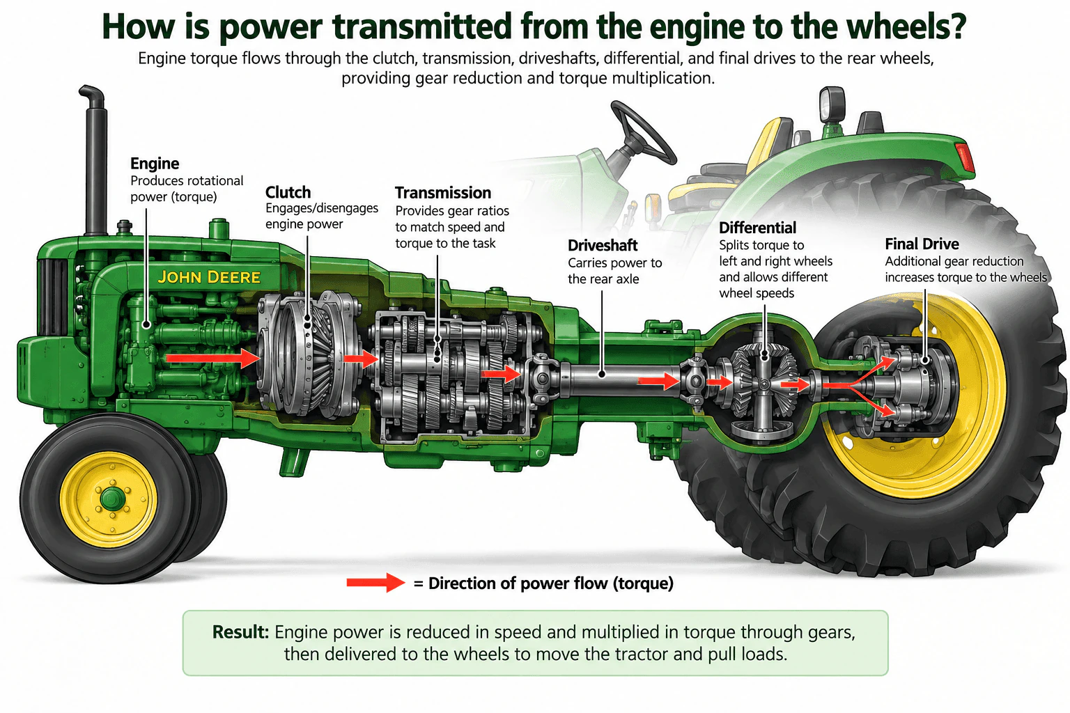
The engine generates rotational torque, which passes through the clutch to the transmission. The transmission selects a gear ratio that trades rotational speed for torque. A driveshaft carries that torque to the differential, which distributes it to the left and right wheel paths while allowing different wheel speeds. Final-drive gearing provides additional speed reduction and torque multiplication before the torque reaches the wheels. The wheels then convert that torque into tractive force at the ground.

Detailed Explanation

The drivetrain is one continuous mechanical power path. The engine is the source of rotational torque. When the clutch is engaged, that torque is transferred into the transmission; when the clutch is disengaged, the engine is separated from the downstream drivetrain. The transmission then selects a gear ratio that matches the required wheel speed and torque. A higher numerical reduction ratio lowers downstream rotational speed and increases available torque, neglecting losses.

From the transmission, the driveshaft carries rotational power toward the axle. The differential receives that torque and routes it into the left and right wheel paths. Its important mechanical function is allowing the two wheels to rotate at different speeds while the drivetrain continues transmitting torque, which is useful during a turn because the outside wheel travels farther than the inside wheel.

After the differential, the final drive provides another gear reduction before torque reaches the wheel. This further reduces rotational speed and increases wheel torque. The wheel and tire then convert that wheel torque into tractive force at the ground. The usable tractive force is limited by factors such as available wheel torque, tire effective radius, tire-ground traction, machine loading, and drivetrain losses.

For mechanical design, I would define the main interfaces as engine-to-clutch, clutch-to-transmission input, transmission output-to-driveshaft, driveshaft-to-differential, differential-to-final-drive, and final-drive-to-wheel. Relevant load cases can include steady pulling load, acceleration, torque reversals, and transient shock loading. Shafts, gears, bearings, splines, fasteners, seals, and housings would be sized from justified loads, material data, and appropriate failure criteria rather than assumed dimensions.

Design checks would include gear tooth loading, shaft torsion and fatigue, bearing capacity and life, spline contact, alignment, backlash, lubrication, sealing, housing stiffness, fits and tolerances, assembly access, and serviceability. Typical general failure modes include clutch wear or slip, gear tooth fatigue or overload, shaft or spline fatigue, bearing wear, lubrication loss, seal leakage, excessive backlash, misalignment, and overheating. These are general drivetrain concerns, not claims about a specific proprietary tractor design.

Validation should progress from component checks to subsystem and complete-drivetrain testing. Useful measurements include input and output torque and speed, temperature, vibration, noise, lubrication behavior, backlash, and wear under representative duty cycles. Test results would be compared with the original load assumptions and design margins. If measured temperatures, wear, deflection, vibration, or durability were unacceptable, the design could be revised through gear sizing, shaft sizing, bearing selection, material choice, lubrication, tolerances, housing stiffness, or service-access changes.

Useful Questions to Ask the Interviewer
  • Are you asking for the general mechanical power path or a specific tractor transmission architecture?
  • Should I assume the conventional clutch, geared transmission, driveshaft, differential, and final-drive arrangement shown here?
  • Do you want only the operating principle, or should I also discuss sizing, failure modes, and validation?
  • Which load condition matters most: normal travel, heavy pulling, acceleration, or transient shock loading?
How is power transmitted from the engine to the wheels? diagram
How to Explain It in an Interview

Start with the power path: engine → clutch → transmission → driveshaft → differential → final drive → wheels. Then explain one function at a time. The engine creates torque. The clutch connects or disconnects the engine from the drivetrain. The transmission selects the speed-to-torque ratio. The driveshaft carries rotational power to the axle. The differential routes torque to the two wheel paths while allowing different wheel speeds. The final drive provides additional reduction before the wheels apply tractive force to the ground.

Then add the design perspective. Explain that the gears, shafts, bearings, splines, seals, housings, fits, and interfaces must be sized from expected loads and validated under representative operating conditions. Finish by noting that more gear reduction generally increases wheel torque while reducing wheel speed, and that the final design must balance performance, durability, manufacturing, cost, assembly, and serviceability.

Practical Complexity & Trade-offs

The main tradeoff is wheel speed versus wheel torque. A higher numerical gear reduction gives more wheel torque but less wheel rotational speed. Larger or stronger gears, shafts, bearings, and housings can carry more load, but they usually add mass, packaging space, manufacturing effort, and cost. Tighter tolerances can improve alignment and backlash control but can increase machining and assembly cost. Lubrication and sealing must protect the gears and bearings while limiting friction and heat. The final design balances performance, durability, manufacturability, assembly, cost, maintainability, and service access.

Why Interviewers Ask This

Interviewers want to confirm that the candidate understands the complete mechanical power path, the purpose of each major drivetrain component, and the tradeoff between rotational speed and torque. They are also evaluating whether the candidate can reason about component interfaces, load cases, likely failure modes, manufacturability, serviceability, and validation without inventing proprietary dimensions or operating data.

Interviewer may ask next
How would you validate that the drivetrain can transmit the required power reliably?

I would first define the required torque, speed, duty cycle, transient loads, operating environment, and component interfaces. Then I would calculate loads on the gears, shafts, bearings, splines, and housings using appropriate material and fatigue data. Prototype or subsystem testing would measure input and output torque and speed, temperature, vibration, noise, lubrication behavior, backlash, and wear under representative load cycles. I would compare those measurements with the design assumptions and margins. If the results showed unacceptable temperature, wear, deflection, vibration, or fatigue risk, I would revise the relevant component sizing, material, bearing selection, lubrication, tolerance, or housing design and repeat the validation.

What would change if the machine needed much more wheel torque for heavy pulling?

I would first consider increasing the overall numerical reduction ratio so more torque is available at the wheels at the cost of lower wheel speed. I would then recalculate loads throughout the drivetrain because the higher transmitted torque may require stronger gears, shafts, bearings, splines, housings, and interfaces. I would also check lubrication, heat generation, fatigue life, packaging, manufacturing cost, serviceability, and tire-ground traction. Increasing drivetrain torque alone does not guarantee more usable pulling force because the tires must still transmit that force to the ground without excessive slip.

3. How did you design a chute?NEWMechanical DesignMediumJohn Deere

Question Details

Describe your own chute-design work.

Short Interview Answer (30-60 seconds)

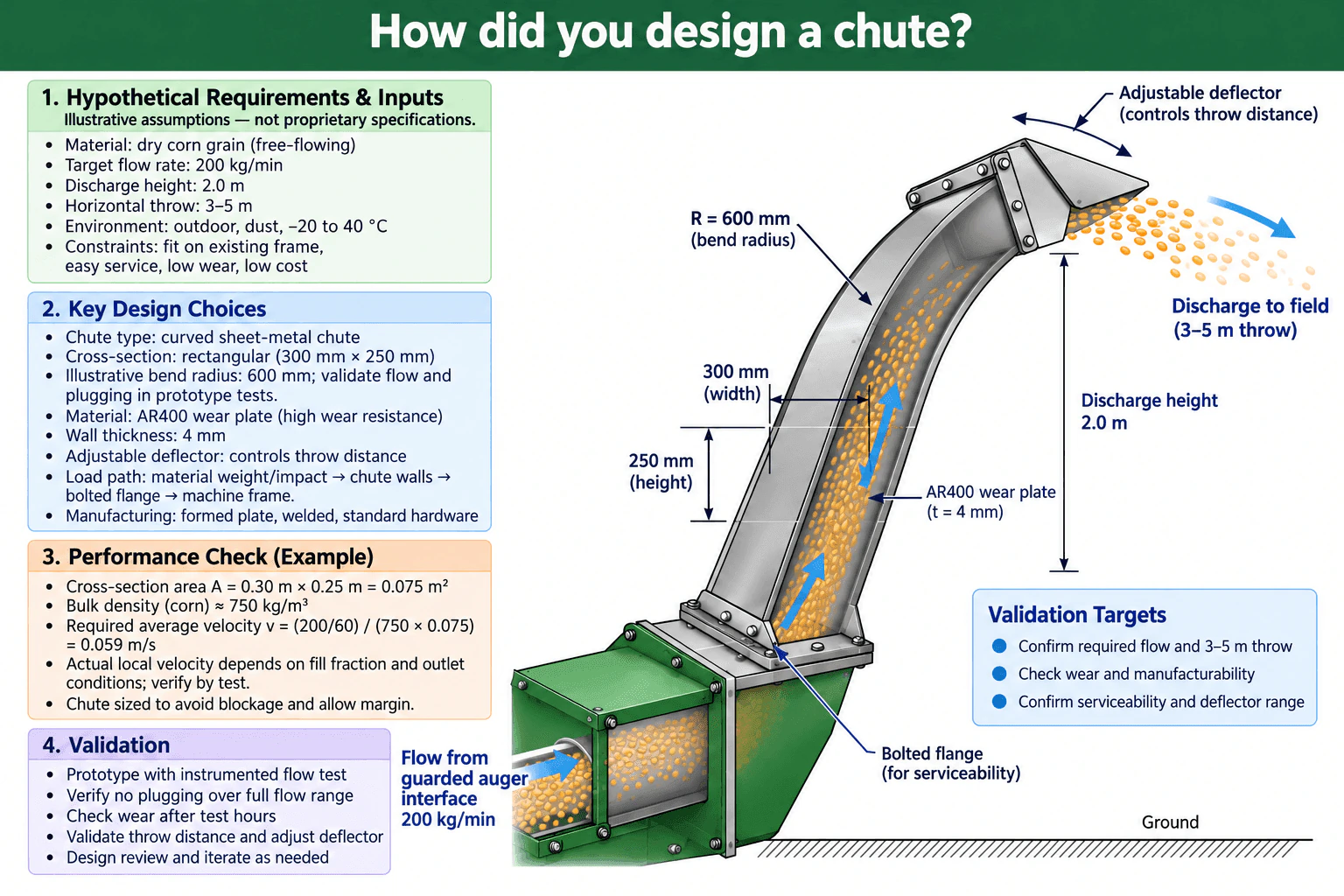
I started by defining the material flow, inlet and outlet interfaces, available space, discharge target, environment, wear, cost, and service requirements. For the illustrative chute, I selected a smooth curved 300 mm × 250 mm rectangular section, a 600 mm starting bend radius, an abrasion-resistant AR400 wear surface, a bolted machine interface, and an adjustable deflector for the 3–5 m throw target. I checked basic flow capacity and the structural load path into the machine frame, then planned prototype tests for plugging, wear, discharge performance, manufacturability, and serviceability before release.

Detailed Explanation

I would describe the chute-design work as a requirements-to-validation process rather than starting with a shape in CAD.

The first step was to define measurable requirements and interfaces. For the illustrative example, the chute handles dry, free-flowing corn at a target mass flow rate of 200 kg/min. The assumed discharge height is 2.0 m, the desired horizontal throw is 3–5 m, and the outdoor operating range is about -20 to 40 °C. The design also needs to fit the available machine frame, limit wear and plugging, remain economical to manufacture, and be practical to service. These values are hypothetical assumptions for explaining the design method, not proprietary product specifications.

I treated the lower inlet as a guarded auger interface feeding material into the chute. At the outlet, I used an adjustable deflector so the discharge direction and throw could be tuned. The main chute is a curved sheet-metal passage with an illustrative rectangular cross-section of 300 mm by 250 mm. A 600 mm bend radius is shown as a starting design assumption. I would not treat that radius as automatically sufficient; I would validate the actual flow and plugging behavior with representative material.

The smooth curvature is important because abrupt steps, sharp transitions, and local restrictions can encourage accumulation, impact, and plugging. I would keep the internal path as continuous as practical and avoid unnecessary changes in cross-sectional area.

For wear resistance, the illustrative design uses AR400 wear plate with a nominal 4 mm thickness. I would treat both the material and thickness as candidate selections rather than final facts. The final choice would depend on wear location, impact severity, forming and welding requirements, mass, cost, and prototype evidence. If only certain regions experience high wear, I would also consider a replaceable wear liner instead of making the entire chute from abrasion-resistant material.

The structural load path is material weight and impact into the chute walls, then through the bolted flange, and finally into the machine frame. I would evaluate the flange, fasteners, local reinforcement, and supporting structure for those loads, including dynamic and vibration effects where relevant. I would also keep service fasteners accessible so the chute or wear components can be removed without unnecessary disassembly of neighboring equipment.

For a basic capacity check, the illustrative cross-sectional area is:

A = 0.30 m × 0.25 m = 0.075 m².

Using an illustrative corn bulk density of 750 kg/m³ and a mass flow rate of 200 kg/min:

m_dot = 200 / 60 = 3.33 kg/s.

The corresponding volumetric flow rate is:

Q = m_dot / rho = 3.33 / 750 = 0.00444 m³/s.

If the full 0.075 m² cross-section were uniformly occupied, the equivalent average velocity would be:

v = Q / A = 0.00444 / 0.075 ≈ 0.059 m/s.

That 0.059 m/s value is only an illustrative capacity calculation. A real bulk-solid chute is generally not uniformly full, so the actual local material velocity depends on fill fraction, inlet momentum, gravity, friction, chute angle, particle interactions, and outlet conditions. I would therefore use this calculation as a sanity check, not as proof that the chute will meet the required performance.

I would then review likely failure modes. Important ones include plugging at a transition, accelerated wear at the bend or outlet, grain damage from excessive impact, deformation of the chute walls, fatigue or loosening at the mounting flange, leakage at joints, poor deflector retention, and difficult service access. Each significant failure mode should have either a design control or a validation test.

Manufacturability and assembly also affect the design. I would favor practical formed sections, accessible welds, standard hardware where appropriate, repeatable flange locations, and an assembly sequence that avoids hidden or inaccessible fasteners. I would apply tighter tolerances only to interfaces where fit, alignment, sealing, or adjustment requires them, rather than applying unnecessarily tight tolerances to the entire chute.

The final stage would be prototype validation. I would run representative material across the required flow range and observe whether the chute accumulates or plugs. I would inspect the high-wear areas after controlled test hours, measure the discharge pattern and 3–5 m throw target, exercise the deflector through its required range, and inspect the flange and fasteners for movement, damage, or loosening. I would also confirm that the design can be manufactured and serviced as intended. Those results would determine whether the bend geometry, outlet shape, wear material, wall thickness, support structure, or deflector needed another iteration.

Useful Questions to Ask the Interviewer
  • What material will move through the chute, and how much do particle size, moisture, and bulk density vary?
  • What are the normal and peak mass-flow requirements?
  • What are the required inlet and outlet locations and the available packaging envelope?
  • Is the main discharge requirement a specific throw distance, a controlled drop location, or a spread pattern?
  • What wear life or maintenance interval is expected?
  • What machine interfaces already exist, and what loads can the supporting structure accept?
  • Are there limits on weight, manufacturing process, cost, cleaning, or field replacement?
  • What flow, plugging, wear, vibration, and discharge tests define successful validation?
How did you design a chute? diagram
How to Explain It in an Interview

I would explain the design in the same order I made the engineering decisions. First, I would state the measurable requirements and interfaces. Second, I would describe the smooth curved geometry, candidate wear material, bolted mounting interface, and adjustable outlet and explain why I chose each one. Third, I would show the load path into the machine frame and one simple flow-capacity calculation while clearly stating its assumptions and limitations. Finally, I would discuss the main failure modes and the prototype tests I would use to verify flow, plugging, wear, throw distance, deflector range, manufacturability, and serviceability. That shows that the chute was designed around requirements, physical behavior, manufacturing, maintenance, and validation rather than just modeled to look correct.

Practical Complexity & Trade-offs

The main tradeoffs are flow performance, wear life, weight, packaging space, cost, manufacturability, and serviceability. A larger or smoother chute can reduce restriction and plugging risk but needs more space and may add mass. A larger bend radius can make the flow path gentler but increases the packaging envelope. A thicker or harder wear material may last longer but can increase weight, cost, and forming or welding difficulty. A replaceable liner adds parts and fasteners but may reduce long-term maintenance cost. An adjustable deflector improves discharge control but adds joints, hardware, and service points. Tolerances should be tight only where fit, sealing, alignment, or adjustment requires them. Simplified calculations can screen concepts, but actual bulk-material behavior, wear, vibration, and discharge performance still need physical validation.

Why Interviewers Ask This

Interviewers want to see whether I can turn an open-ended mechanical problem into measurable requirements, define interfaces and load cases, choose geometry and materials for defensible reasons, consider manufacturing and service access, identify failure modes and tradeoffs, and validate the design instead of assuming that a CAD model or simplified calculation proves it will work.

Interviewer may ask next
How would you validate that the chute will not plug?

I would identify the conditions most likely to cause plugging, such as peak flow, increased moisture, particle-size variation, reduced outlet clearance, and accumulation at transitions. I would inspect the geometry for sharp steps, sudden area reductions, dead zones, and rough internal joints. Then I would prototype the chute and run representative material across the expected flow range while observing accumulation and measuring throughput. I would repeat the test under credible difficult material conditions. If plugging occurred, I would use its location to guide a specific geometry change, such as increasing local clearance, smoothing a transition, or changing the bend or outlet shape, and then retest.

What would you change if the chute had to be lighter without sacrificing wear life?

I would separate the structural function from the wear function instead of simply thinning every wall. One option would be a lighter structural shell with replaceable abrasion-resistant material only in the regions that experience significant sliding or impact wear. I would use prototype inspection or wear data to identify those regions, then recheck shell stiffness, flange loads, fastener loads, vibration, manufacturing, and liner attachment. The final choice would balance mass reduction against added parts, assembly effort, service time, and life-cycle cost.

4. What are the types of waste in a manufacturing process?NEWManufacturingEasyJohn Deere

Short Interview Answer (30-60 seconds)

In Lean manufacturing, the eight common types of waste are defects, overproduction, waiting, non-utilized talent, transportation, inventory, motion, and extra-processing. A common way to remember them is DOWNTIME. For example, producing parts before they are needed is overproduction, an operator waiting for a machine is waiting waste, and unnecessary movement of material is transportation waste. The goal is to identify these non-value-added activities, determine their root causes, and reduce them without creating quality, safety, or production problems elsewhere.

Detailed Explanation

Manufacturing waste is an activity that uses resources but does not create value that the customer needs. In Lean manufacturing, the eight common wastes are often remembered with the acronym DOWNTIME.

  1. Defects: Parts or products that do not meet requirements and therefore require scrap, rework, repair, sorting, or additional inspection. Defects consume material, labor, machine time, and production capacity.
  1. Overproduction: Producing more than is currently needed or producing earlier than required. Overproduction can create excess inventory, storage, handling, and quality problems and can hide other process issues.
  1. Waiting: People, machines, or material sitting idle because the next required activity cannot begin. Examples include waiting for parts, tooling, inspection, instructions, machine availability, or maintenance.
  1. Non-utilized talent: Failing to make effective use of employees' knowledge, experience, skills, or improvement ideas. For example, repeatedly ignoring an operator's observations about a recurring production issue can prevent useful process improvements.
  1. Transportation: Unnecessary movement of material, parts, tools, or finished products between locations. Transportation consumes time and handling effort and may increase the risk of damage.
  1. Inventory: More raw material, work-in-process, or finished goods than the process currently requires. Excess inventory uses space and capital and can hide defects, flow problems, equipment instability, and production imbalance.
  1. Motion: Unnecessary movement by people or equipment while performing work. Examples include excessive walking, reaching, bending, searching for tools, or repeatedly repositioning a component because of poor workstation layout.
  1. Extra-processing: Performing more work than is required to meet the product specification or customer need. Examples can include unnecessary machining operations, redundant inspections, excessive finishing, or holding a tighter tolerance than the product function actually requires.

Identifying the waste category is only the first step. I would observe the actual process, distinguish value-added work from necessary support work and avoidable non-value-added work, quantify the important losses where practical, and investigate the root cause before changing the process.

For example, if operators frequently wait for components, simply asking them to work faster would not solve the problem. I would investigate material flow, production scheduling, equipment reliability, cycle-time balance, replenishment, and any upstream constraint that is creating the delay.

The waste categories can also interact. Overproduction may create excess inventory, which then requires additional transportation and handling. Defects may create extra-processing through rework and can also cause downstream waiting. Because of these interactions, an engineer should evaluate the complete production flow instead of optimizing one workstation in isolation.

A proposed improvement must also preserve required quality, safety, process capability, and production reliability. Removing inspection, inventory, machining operations, or cycle time is not an improvement if the change causes uncontrolled critical characteristics, more defects, unsafe work, or unstable production.

Useful Questions to Ask the Interviewer
  • What product and manufacturing process are being evaluated?
  • Where is the current bottleneck or largest observed loss?
  • What production volume, takt time, or demand rate is required?
  • Which operations directly create customer-required value?
  • What defect, scrap, rework, downtime, inventory, or cycle-time data are available?
  • Are there critical dimensions, safety-related characteristics, or regulatory requirements that require specific controls?

These questions help distinguish genuine waste from work that may be necessary for quality, safety, compliance, or stable process control.

How to Explain It in an Interview

I would first state the eight wastes clearly: defects, overproduction, waiting, non-utilized talent, transportation, inventory, motion, and extra-processing. Then I would give one or two simple manufacturing examples to show practical understanding. Finally, I would explain that Lean improvement is not simply about removing steps. I would confirm what work actually adds value, identify the root cause of non-value-added activity, make a targeted improvement, and verify the result with appropriate measures such as cycle time, scrap, work-in-process, downtime, or first-pass quality. That demonstrates both knowledge of Lean terminology and the engineering judgment required to apply it.

Technical Approach
  1. Define the product, process boundaries, customer requirements, and required production output.
  2. Observe the actual production flow from incoming material through the completed product.
  3. Separate customer-value-added work from necessary support work and avoidable non-value-added work.
  4. Classify observed waste as defects, overproduction, waiting, non-utilized talent, transportation, inventory, motion, or extra-processing.
  5. Quantify important losses where suitable data are available, such as scrap, rework, waiting time, travel distance, work-in-process, downtime, or unnecessary cycle time.
  6. Investigate root causes rather than treating the waste category itself as the root cause.
  7. Develop an improvement that reduces the waste while maintaining required quality, safety, process capability, and production output.
  8. Implement the change in a controlled manner and compare relevant before-and-after measures.
  9. Standardize and monitor the improved process so the waste does not gradually return.
Practical Insights

The main tradeoff is that removing apparent waste must not remove activities that are necessary for quality, safety, or stable production. For example, reducing inventory can expose process instability, eliminating an inspection step may be inappropriate when the process cannot yet provide sufficient capability evidence, and reducing cycle time too aggressively can increase defects. Engineers therefore evaluate the complete production flow and verify improvements with measurable results rather than assuming that fewer steps always mean a better process.

Why Interviewers Ask This

Interviewers ask this to check whether you understand Lean manufacturing and can recognize activities that consume time, labor, material, space, or equipment capacity without adding customer value. They also want to see whether you can connect the waste categories to practical production improvements rather than only memorizing their names.

Common interview mistakes

Common mistakes include remembering only the original seven wastes and forgetting non-utilized talent; confusing transportation of material with motion of a worker; assuming that all inventory or inspection is automatically waste without understanding why it exists; focusing only on visible scrap while ignoring waiting, overproduction, or extra-processing; treating the waste category as the root cause; and removing one waste in a way that creates another problem elsewhere in the production system.

Interview tip

Use the DOWNTIME acronym to remember all eight wastes, but do not stop at listing them. Give a practical manufacturing example and explain how you would observe the process, measure the loss, find the root cause, improve the process, and validate the result. That shows that you can apply Lean principles rather than only recite terminology.

Interviewer may ask next
How would you verify that a change actually reduced manufacturing waste?

I would first define a measurable baseline that matches the waste being addressed. Depending on the problem, that could include scrap rate, first-pass yield, rework hours, waiting time, work-in-process inventory, travel distance, downtime, or cycle time. After implementing the change under comparable operating conditions, I would measure the same indicators again and also check that quality, safety, process capability, and downstream performance did not deteriorate. A successful improvement should reduce the targeted waste without simply moving the loss to another part of the process.

What if reducing inventory causes the production line to stop more frequently?

That indicates the inventory may have been masking another problem, such as unreliable equipment, inconsistent material delivery, long changeovers, poor scheduling, or unbalanced cycle times. I would identify and address the cause of the interruptions instead of assuming that the lowest possible inventory is always best. I would then determine an appropriate inventory level that supports reliable production without creating unnecessary excess.

5. How is a clutch manufactured?NEWManufacturingMediumJohn Deere

Short Interview Answer (30-60 seconds)

A clutch is manufactured as an assembly of separately produced parts rather than by one single process. For a typical dry friction clutch, components such as the pressure plate, hub, cover, driven plate, springs, and friction facings are made using processes such as casting or forging, sheet-metal stamping, machining, forming, and friction-material processing. Critical locating and friction surfaces are machined or finished to control dimensions, flatness, runout, and surface finish. Heat treatment may be used where the specified material needs additional strength, hardness, fatigue resistance, or wear resistance. The parts are then inspected, assembled in controlled fixtures, and checked for alignment, movement, balance where required, and functional performance before production release.

Detailed Explanation

A clutch is best treated as a manufactured assembly, not as one part made by one process. Assuming the interviewer means a typical dry friction clutch, the assembly may include a clutch disc or driven plate, hub, friction facings, pressure plate, cover, springs, fasteners, and related locating features. Each part has different geometry, loading, wear, tolerance, and cost requirements, so each part can require a different manufacturing process.

The first step is to understand the requirements. I would identify the specified material, part geometry, load path, production volume, dimensional tolerances, surface-finish requirements, wear surfaces, thermal exposure, and cost target. I would then choose the primary manufacturing process for each component rather than assuming that every part should be machined.

For relatively thick load-carrying metallic components such as a pressure plate, an appropriate starting process might be casting or forging, depending on the specified material, shape, mechanical-property requirements, production volume, tooling cost, and expected loading. Critical surfaces can then be machined or ground where the drawing requires controlled flatness, concentricity, runout, thickness, or surface finish.

A clutch hub must transmit torque, so its manufacturing route must produce the required geometry and mechanical properties. Depending on the design and material, the blank may be forged or produced from another suitable starting form and then machined. Splines or other torque-transmitting features can be produced using an appropriate forming, broaching, shaping, hobbing, machining, or similar production process selected from the geometry, tolerance, volume, and cost requirements. I would not assume a specific process without the drawing and production requirements.

A clutch cover is often suitable for sheet-metal production when its geometry and volume justify it. Typical operations can include blanking, stamping, drawing or forming, piercing, trimming, and secondary operations. At high volume, dedicated dies can reduce cycle time and improve repeatability, while prototypes may use simpler tooling or more flexible fabrication methods.

The clutch disc is itself an assembly. A metallic driven plate or carrier is formed or otherwise produced to the required geometry. The hub and any torsional springs or compliant elements are manufactured separately. Friction facings are produced from the specified friction material and attached to the disc using the joining method required by the design, such as mechanical fastening or another specified process. Important characteristics can include facing thickness, parallelism, attachment quality, position, and mass distribution because variation can affect engagement, vibration, heat generation, and wear.

Heat treatment is selected only when required by the specified material and functional requirement. For example, a torque-carrying or repeatedly loaded component may require controlled strength, hardness, fatigue resistance, or wear resistance. The exact heat-treatment method cannot be selected responsibly without knowing the alloy, required properties, and drawing requirements. Heat treatment can also introduce distortion, so the manufacturing sequence may require finishing or machining of critical surfaces after heat treatment.

Surface finishing is especially important on functional interfaces. Machining or grinding may be used when friction or locating surfaces require specific flatness, runout, thickness, or roughness. The drawing tolerance should determine the process. Making every surface highly precise would increase cycle time, inspection effort, tooling cost, and scrap without improving clutch performance if those surfaces are not functionally critical.

The manufacturing route also changes with production volume. Prototype parts favor flexible processes, general-purpose machining, and simple fixtures because the design may still change. High-volume production can justify dedicated dies, molds or forging tooling where applicable, specialized fixtures, gauges, automated handling, and automated assembly because the tooling investment is distributed across many parts and can reduce variation and cycle time.

Quality control should concentrate on critical characteristics. Depending on the design, these may include dimensions, flatness, concentricity, axial or radial runout, friction-surface finish, spline fit, spring characteristics, facing thickness, and assembled alignment. Inspection access should be considered during design for manufacturability so the important characteristics can actually be measured. Fixtures and gauges should reference meaningful datums that relate to the component's function.

For production characteristics controlled statistically, I would first verify that the measurement system is suitable and that the manufacturing process is stable. Only then would I interpret capability indices such as Cp and Cpk. Cp compares the process spread with the specification width, while Cpk also considers how well the process is centered within the specification limits. A process can therefore have an acceptable potential spread but still perform poorly if its mean is shifted toward one specification limit. Statistical process control can be used on appropriate critical characteristics to detect process shifts or trends before they create unacceptable parts.

The individual parts are then assembled using controlled fixtures and a defined sequence so the components remain aligned while springs, friction elements, the cover, fasteners, and other parts are installed. Fastening processes must meet the drawing and assembly requirements. If rotating balance is a specified characteristic, the applicable components or completed assembly should be checked and corrected according to the product requirements.

Final validation should include the required dimensional checks and functional tests. Depending on the clutch design, validation may assess engagement and release behavior, torque transmission, balance, thermal behavior, wear, durability, or other specified performance characteristics. Production readiness should also consider tooling life, cycle time, scrap, rework, inspection time, traceability, and reaction plans for nonconforming output.

A production control plan can document the important characteristics, process step, measurement or monitoring method, sampling approach, and reaction plan. Before sustained production, representative parts should be produced with production-intent tooling and equipment and checked against the required dimensional and functional acceptance criteria.

The overall manufacturing logic is therefore: choose the appropriate primary process for each clutch component, use secondary machining or finishing only where tighter control is functionally necessary, apply required material treatments, inspect critical characteristics, assemble the parts with controlled tooling, and validate both the production process and completed clutch against the specified requirements.

Useful Questions to Ask the Interviewer
  • Are we discussing a dry friction clutch, a wet clutch, or another clutch architecture?
  • What materials are specified for the pressure plate, hub, cover, disc, springs, and friction surfaces?
  • Is this for prototype, low-volume, or high-volume production?
  • Which characteristics are functionally critical, such as flatness, runout, spline fit, friction-surface finish, facing thickness, or balance?
  • What cycle-time, tooling, cost, or available-equipment constraints apply?
  • What dimensional and functional validation is required for production release?
How to Explain It in an Interview

I would explain that a clutch is not manufactured using one process. I would first break the assembly into its main components and select the manufacturing process for each one from its material, geometry, tolerance, production volume, mechanical requirements, and cost. For example, thicker load-carrying components may begin as castings or forgings, a high-volume cover may use sheet-metal stamping, and critical interfaces may require machining or grinding. I would then account for any required heat treatment, friction-material production and attachment, inspection access, fixtures, and assembly tooling. Finally, I would define critical characteristics, verify measurement and process stability before using Cp or Cpk, use a control plan where appropriate, and validate the assembled clutch dimensionally and functionally before production release.

Technical Approach
  1. Define the clutch architecture and identify each manufactured component.
  2. Establish the specified material, geometry, loading, tolerance, surface-finish, production-volume, and cost requirements for each component.
  3. Select an economical primary process such as casting, forging, sheet-metal forming, machining, or another appropriate process based on those requirements.
  4. Add machining, grinding, or other secondary finishing only where functional dimensions, datum relationships, fit, flatness, runout, or surface finish require tighter control.
  5. Determine whether heat treatment or another material-conditioning step is required and place it appropriately in the process sequence while accounting for possible distortion.
  6. Define how friction materials, springs, hubs, covers, and other subcomponents are produced and joined.
  7. Design fixtures, tooling, and inspection access around functional datums and critical characteristics.
  8. Establish dimensional inspection, suitable measurement-system verification, process monitoring, and a control plan for critical characteristics.
  9. Evaluate process capability using Cp and Cpk only after confirming measurement suitability and process stability.
  10. Assemble the components using controlled fixtures and a defined sequence.
  11. Perform the required dimensional, balance, movement, and functional validation.
  12. Review scrap, rework, cycle time, tooling life, and production data before sustained manufacturing release.
Practical Insights

The main manufacturing tradeoff is between flexibility, precision, production rate, tooling investment, material utilization, and cost. Machining is flexible and can produce accurate features, but using it unnecessarily can increase cycle time and material waste. Casting can economically create complex shapes when appropriate for the material and volume, but critical surfaces may still need machining. Forging can provide a strong starting form for highly loaded components, but it requires tooling and often secondary machining. Sheet-metal stamping can produce parts rapidly at high volume, but dedicated dies may be difficult to justify for prototypes or low-volume production. Tight tolerances and fine finishes should therefore be specified only where clutch function requires them. Process capability is also important: a narrow process spread is not enough if the process is unstable, poorly centered, or measured with an unsuitable inspection system. Scrap, rework, tooling wear, fixture variation, inspection time, and cycle time all contribute to the real manufacturing cost.

Why Interviewers Ask This

Interviewers are evaluating whether I can break a mechanical assembly into its major components, select realistic manufacturing processes based on material, geometry, tolerance, production volume, and cost, and connect those processes to heat treatment, surface finish, inspection, tooling, process capability, and final assembly. They also want to see whether I understand that a clutch is not manufactured by one process; different components require different manufacturing routes and quality controls.

Common interview mistakes

Common mistakes include describing the entire clutch as simply cast or machined instead of recognizing that it is an assembly of differently manufactured components; selecting a process without considering material, geometry, tolerance, volume, and cost; assuming every surface needs high-precision machining; specifying heat treatment without knowing the material and property requirements; ignoring heat-treatment distortion and process sequencing; overlooking functional datums, tooling, and inspection access; discussing Cp or Cpk without first establishing a suitable measurement system and process stability; failing to distinguish prototype methods from production-intent processes; and describing assembly without considering alignment, balance where required, cycle time, scrap, or functional validation.

Interview tip

Organize the response component by component and connect each process choice to a manufacturing reason. A strong answer follows a clear sequence: economical primary process for the basic shape, secondary machining or finishing for critical features, material treatment where required, inspection of critical characteristics, controlled assembly, and functional validation. Avoid inventing a specific alloy, tolerance, heat-treatment specification, capability value, or employer-specific procedure unless the interviewer provides it.

Interviewer may ask next
How would you validate that the clutch manufacturing process can consistently hold a critical dimension?

I would first confirm that the characteristic is defined from meaningful functional datums and that the measurement system has adequate resolution, repeatability, and reproducibility for the tolerance being evaluated. I would then collect representative production data under normal operating conditions and use statistical process-control methods to determine whether the process is stable. Only after measurement suitability and process stability are established would I calculate and interpret capability indices such as Cp and Cpk. Cp indicates how the process spread compares with the specification width, while Cpk also considers process centering. I would also review control-chart behavior and process conditions because a capability number alone does not identify causes such as tool wear, fixture movement, material variation, or temperature effects. If capability is inadequate, I would identify and reduce the dominant sources of variation, then repeat the validation.

How would the manufacturing approach change if the clutch moved from prototype quantities to high-volume production?

For prototypes, I would favor flexible manufacturing methods, general-purpose machining, and simple or adjustable fixtures because the design may still change and expensive dedicated tooling may not be justified. For high-volume production, I would reconsider each component for lower-unit-cost processes such as dedicated casting or forging tooling where appropriate, sheet-metal stamping for suitable parts, specialized machining fixtures, dedicated gauges, automated handling, and automated assembly when economically justified. I would also place greater emphasis on tooling life, preventive maintenance, cycle-time reduction, error-proofing, process capability, statistical process control, scrap reduction, and formal control plans. The goal is not simply to automate the prototype process but to create a stable, repeatable production system that meets the required clutch performance at the desired rate and cost.

6. Do you know about CFD?NEWSimulation And Engineering AnalysisEasyJohn Deere

Question Details

Discuss your familiarity with computational fluid dynamics.

Short Interview Answer (30-60 seconds)

Yes. CFD stands for computational fluid dynamics. It uses numerical methods to solve governing conservation equations for fluid flow and, when required, heat transfer. I would start by defining the engineering question, geometry, fluid properties, operating conditions, and boundary conditions. I would then select suitable physics such as laminar or turbulent flow, generate a good-quality mesh, solve while checking residuals and conservation, perform a mesh-convergence study where appropriate, and compare the results with hand calculations or test data. The key point is that solver convergence alone does not prove that the CFD model represents the real system correctly.

Detailed Explanation

CFD, or computational fluid dynamics, is a numerical approach for studying how liquids or gases move by dividing the fluid region into computational cells and solving the governing conservation equations across that domain. Depending on the problem, those equations represent conservation of mass, momentum, and energy. CFD can predict quantities such as velocity, pressure, temperature, flow rate, pressure drop, forces, and heat-transfer behavior without physically building every design option. However, the usefulness of the result depends on the assumptions, boundary conditions, mesh, physical models, numerical convergence, verification, and validation.

Useful Questions to Ask the Interviewer
  • What engineering decision must the CFD analysis support?
  • Which result is most important, such as pressure drop, cooling performance, flow distribution, drag, or temperature?
  • What inlet, outlet, wall, and operating conditions are known?
  • Is the flow expected to be steady or transient?
  • Is compressibility important?
  • Is heat transfer involved?
  • What fluid-property information is available?
  • Is the flow expected to be laminar or turbulent?
  • Are experimental measurements, previous designs, or hand calculations available for comparison?

These questions help determine the required model fidelity instead of automatically choosing the most complicated simulation.

How to Explain It in an Interview

I would describe the CFD process as a sequence of engineering decisions. First, I would define the physical domain, coordinate system, consistent units, operating conditions, and the specific output needed for the decision. Then I would identify the governing physics. Conservation of mass and momentum are fundamental for fluid-flow problems, while the energy equation is also required when temperature or heat transfer is important. Additional models may be required for turbulence, rotating regions, multiphase flow, compressibility, or other effects, but I would include them only when the engineering problem requires them.

Next, I would define realistic boundary conditions. Examples can include a specified inlet velocity or mass flow, inlet temperature, outlet pressure, wall temperature or heat flux, and no-slip wall conditions. The exact choice depends on what is physically known. Boundary conditions must represent the actual system because a model can converge numerically while still being physically wrong if its constraints are unrealistic.

I would then create the computational mesh. The mesh needs enough resolution to capture the important flow and thermal gradients without making the model unnecessarily expensive. Areas such as boundary layers, narrow passages, wakes, jets, sharp flow changes, or regions with strong temperature gradients may require local refinement. I would also check mesh quality because poorly shaped cells can reduce accuracy or create convergence problems.

During the solution, I would monitor solver residuals, but I would not use residuals as the only convergence criterion. I would also track engineering quantities of interest such as pressure drop, mass flow, force, or temperature and check conservation of mass and energy where applicable. A credible converged solution should have stable quantities of interest and acceptable conservation behavior, not merely residuals below a chosen threshold.

For numerical verification, I would perform a mesh-convergence study when the engineering decision warrants it. I would refine the mesh and check whether the important result changes materially. If the result changes significantly as the mesh is refined, the earlier solution is still sensitive to discretization. I would also examine sensitivity to important assumptions, uncertain boundary conditions, and modeling choices when they could affect the conclusion.

Validation is different from verification. Verification asks whether the mathematical model is being solved with adequate numerical accuracy, while validation asks whether the selected model and assumptions represent the real physical system adequately for the intended use. I would therefore compare CFD predictions with hand calculations, analytical relationships, trusted reference data, or experimental measurements when suitable evidence is available. Solver convergence alone is not sufficient validation.

Finally, I would interpret the results in terms of the original engineering decision and clearly communicate assumptions, sensitivities, and limitations. For example, if the result depends strongly on an uncertain inlet condition or turbulence-model choice, I would state that sensitivity rather than presenting one contour or numerical value as exact. CFD is most useful when sound physics, numerical verification, engineering judgment, and real-world validation are used together.

Technical Approach
  1. Define the engineering question and the output needed for the decision.
  2. Define the fluid domain, coordinate system, units, operating conditions, known inputs, and important unknowns.
  3. Select the required physics, such as incompressible or compressible flow, steady or transient behavior, heat transfer, and an appropriate turbulence treatment if needed.
  4. Assign fluid properties and realistic inlet, outlet, wall, and other boundary conditions.
  5. Generate a mesh with suitable refinement in regions where strong gradients are expected and check mesh quality.
  6. Solve the governing conservation equations using appropriate numerical settings.
  7. Monitor residuals together with engineering quantities such as mass flow, pressure drop, force, or temperature.
  8. Check conservation and investigate physically unrealistic behavior or unstable quantities of interest.
  9. Perform mesh-convergence and sensitivity studies where they are important to the engineering decision.
  10. Verify numerical behavior using mesh refinement, hand calculations, analytical relationships, or limiting cases where appropriate.
  11. Validate the model against experimental measurements or trusted physical evidence when available.
  12. Interpret the results, state assumptions and uncertainty, and connect the findings to the engineering decision.
Practical Insights

CFD involves a tradeoff between model fidelity, numerical accuracy, and computational cost. A finer mesh or more detailed physical model can resolve more behavior but generally requires more memory and solution time. A simpler model can be preferable when its assumptions are appropriate for the engineering decision. The goal is not to maximize complexity, but to use enough fidelity to answer the question reliably. Uncertainty in boundary conditions, fluid properties, turbulence modeling, geometry, mesh resolution, and other assumptions can affect the result, so important sensitivities should be checked.

Why Interviewers Ask This

The interviewer is evaluating whether the candidate understands what CFD is, where it is useful, and how to judge whether a simulation is physically credible rather than simply accepting a solver result.

Common interview mistakes

Common mistakes include treating attractive contour plots as proof of accuracy, using unrealistic boundary conditions, choosing a turbulence or other physical model without checking whether its assumptions fit the problem, using a mesh that is too coarse in important regions, judging convergence from residuals alone, ignoring mass or energy conservation, skipping mesh-convergence checks when they matter, and confusing numerical verification with physical validation. Another mistake is adding unnecessary model complexity that increases computational cost without improving the engineering decision.

Interview tip

For an easy CFD interview question, begin with a clear definition and then show that you understand the complete credibility chain: appropriate physics, realistic boundary conditions, mesh quality, convergence, verification, and validation. Mentioning that solver convergence alone does not establish physical accuracy demonstrates stronger engineering judgment than simply listing CFD software or simulation features.

Interviewer may ask next
How would you check whether a CFD result is reliable?

I would check reliability in several layers. First, I would verify that the geometry, fluid properties, operating conditions, physical models, and boundary conditions represent the intended problem. I would check mesh quality and perform a mesh-convergence study when appropriate. During the solve, I would monitor residuals and important engineering quantities and check conservation of mass and energy where applicable. I would then compare the prediction with a hand calculation, analytical relationship, limiting case, trusted reference data, or experimental measurements when available. This separates numerical verification from physical validation and avoids assuming that a converged solver result is automatically correct.

What would you do if a more detailed CFD model greatly increased computation time?

I would return to the engineering decision and determine whether the additional fidelity could materially change that decision. If a simpler model represents the important physics within acceptable uncertainty, I would prefer it because it is faster to build, solve, and investigate. If the decision depends on effects that the simpler model cannot represent, I would use the higher-fidelity model and focus computational effort on the important regions or operating cases. I would support that choice with sensitivity checks rather than assuming that the most complicated model is automatically the best model.

7. Describe a time when you learned something from a person who had a different background or nationality than you.NEWBehavioralEasyJohn Deere

Question Details

Focus on what you learned from that person.

Interview tip:

Use STAR to structure your answer: briefly explain the Situation and Task, make Action the most detailed part, and finish with the Result. For example, describe a mechanical design project where you worked with an engineer from a different country, noticed a different way of reviewing design risks, asked questions to understand the reasoning, applied what you learned, and improved how you approached future design reviews.

Situation

During a previous mechanical design project, I worked closely with an engineer from another country who had a different engineering and manufacturing background from mine. We were reviewing a component that needed to be reliable while also being practical to manufacture and assemble.

Task

My responsibility was to review the mechanical design and help identify risks before the design moved forward. I was used to starting with calculations, material limits, and whether the part met the drawing requirements. My colleague approached the review differently and spent more time asking how the part would actually be produced, handled, assembled, and serviced.

Action

Instead of assuming that my usual review method was better, I asked him to explain why he focused so much on the manufacturing and assembly sequence. He showed me that a design can satisfy its calculations and still create problems if access is difficult, tolerances are hard to control, or the assembly process allows a part to be installed incorrectly. I started reviewing the design with him step by step from the viewpoint of the people who would manufacture and assemble it. I asked questions about tool access, part orientation, tolerance variation, and how someone could detect an incorrect assembly. I then compared those observations with my original engineering review. This helped me see that the strongest design review combines analytical checks with practical knowledge from manufacturing and field experience. I also learned to ask more questions before defending my first idea, because a different working background can reveal risks that I may not notice on my own.

Result

We identified practical design concerns earlier and made the design easier to review from both an engineering and manufacturing perspective. More importantly, I changed how I approach design reviews. I now make a deliberate effort to understand how people with different technical and cultural backgrounds see the same problem, because their experience can expose assumptions in my own thinking and help me make better engineering decisions.

Why Interviewers Ask This

Interviewers ask this question to understand whether a candidate is open to different perspectives and can learn from people whose experiences are different from their own. A strong answer shows respect, curiosity, active listening, adaptability, and the ability to turn a new perspective into better professional judgment.

Interviewer may ask next
What was the most important thing you learned from that engineer?

The most important lesson was that a technically correct design is not automatically a practical design. I learned to consider manufacturing, assembly, service access, and possible human errors earlier instead of treating them as checks that happen after the main design work.

How has that experience changed the way you work with people from different backgrounds now?

I ask more questions before forming a final opinion. When someone approaches a problem differently, I try to understand what experience is behind that approach. I then compare their perspective with my own engineering reasoning and use the strongest ideas from both. That has made me more thoughtful during design reviews and more effective when working with diverse teams.

8. Describe a time when communication was critical.NEWBehavioralMediumJohn Deere

Question Details

Use an occasion in which communication mattered.

Interview tip:

Use STAR to structure your answer: briefly explain the Situation and Task, make Action the most detailed part, and finish with the Result. For example, describe a project where a design change affected manufacturing and quality, explain your responsibility, show how you communicated the change clearly to each group, confirmed everyone had the same understanding, and helped the team implement the change without creating new problems.

Situation

During a previous project, I was supporting a mechanical assembly that needed a design change before the next production build. The change affected a component dimension and also changed how the part needed to be inspected. Engineering understood the reason for the change, but manufacturing and quality were working from different information. I realized that unclear communication could lead to the old part being produced or inspected using the wrong requirement.

Task

My responsibility was to make sure the technical change was understood correctly by everyone who needed to use it. I also needed to explain why the change mattered, what documents were affected, and when the updated requirement should be used.

Action

I first reviewed the drawing change and confirmed exactly which dimension and inspection requirement were affected. Then I spoke directly with the manufacturing and quality teams instead of relying only on the drawing release notification. I explained the problem in simple terms and showed the old requirement beside the new requirement so the difference was clear. I explained why the dimension had changed and what could happen if the old value was still used. I also asked each group how the change affected its work. Manufacturing pointed out that the work instructions also needed to be updated, while quality identified an inspection document that still referenced the previous requirement. I worked with the responsible team members to make sure those documents were corrected. Before the next build, I confirmed that the latest drawing and supporting instructions were available at the point of use. I also asked the people performing the work to explain the change back to me in their own words. That helped me confirm that the message had been understood instead of assuming that sending information was enough.

Result

The team entered the next build with the same understanding of the design and inspection requirements. The updated component was produced and checked using the correct information, and we avoided confusion during the build. I learned that communication is not complete when information is sent. It is complete when the people receiving it understand what changed, why it matters, and what they need to do differently.

Why Interviewers Ask This

Interviewers ask this question to understand whether a candidate can communicate important technical information clearly when several people or functions depend on it. A strong answer shows that the candidate adjusts the message for the audience, checks understanding, listens to concerns, and takes ownership of preventing mistakes caused by unclear information.

Interviewer may ask next
Why did you speak directly with manufacturing and quality instead of relying only on the drawing update?

I knew that releasing the drawing did not guarantee that everyone would notice the specific change or understand how it affected their work. Speaking directly with both groups let me explain the reason for the change, answer questions, and discover that other documents also needed updates. It gave me confidence that the technical information would be applied correctly.

What would you do differently if you faced a similar communication issue now?

I would involve manufacturing and quality slightly earlier in the change process. Their feedback helped identify affected work instructions and inspection documents, so bringing them in earlier could make the change process smoother. I would still confirm understanding before the work started because that was the most important lesson from the situation.

9. Describe a time when you were not able to meet a customer's needs.NEWBehavioralHardJohn Deere

Question Details

Use an experience in which customer needs went unmet.

Interview tip:

Use STAR to structure your answer: briefly explain the Situation and Task, make Action the most detailed part, and finish with the Result. For example, describe a project where a customer requested a design change that could not be delivered within the available schedule or technical limits, how you evaluated the request, communicated the constraint, proposed practical alternatives, and handled the final outcome.

Situation

During a previous project, I was supporting the mechanical design of an equipment assembly that had already entered a late stage of development. The customer asked for an additional adjustment feature that would have made the equipment easier to use in one of their operating conditions. After reviewing the request, I found that adding the feature would require changes to the surrounding structure, interfaces, and validation work. We could not complete those changes safely within the agreed delivery schedule.

Task

I was responsible for evaluating the request and helping the team decide what could realistically be delivered. I also needed to make sure the customer understood why we could not fully meet the request rather than simply telling them no.

Action

I first reviewed the existing design, available space, load path, and interfaces to understand what the requested change would affect. I then discussed the change with the manufacturing and test teams because even a small mechanical modification could create new fabrication or validation work. Based on that review, I concluded that adding the full feature at that stage would create too much technical and schedule risk. I documented the main constraints in simple terms and explained them to the customer early. I focused on the reason behind the request and learned that their main concern was making setup easier for operators. I then worked with the team to identify a smaller adjustment to the existing design that improved access without changing the main structure. I was clear that this alternative would not satisfy the entire request, but I explained what it could improve and what would need to be considered in a future design revision. I also recorded the original request and the technical findings so the need would not be lost after the current project was completed.

Result

We were not able to meet the customer's full need in that release, but the customer understood the technical and schedule limits and accepted the smaller improvement. The project continued without introducing an unvalidated design change. I learned that when I cannot meet a customer need, I should explain the constraint early, understand the need behind the request, offer the best practical option available, and make sure the remaining need is captured for future work.

Why Interviewers Ask This

Interviewers ask this question to see how a candidate responds when customer expectations cannot be fully satisfied. A strong answer shows practical judgment, clear communication, ownership, and the ability to balance customer needs with technical limits, safety, quality, and delivery commitments.

Interviewer may ask next
Why did you choose not to make the full design change even though the customer wanted it?

I chose not to make the full change because my review showed that it affected the structure, interfaces, manufacturing work, and validation plan. Making that change late in the project without enough time to verify it would have created unnecessary risk. I felt it was better to be transparent with the customer and offer a smaller safe improvement than promise something we could not properly validate.

What would you do differently if you faced a similar situation again?

I would try to identify the underlying customer need even earlier in the project so we would have more design options before the system became difficult to change. I would also involve manufacturing and test teams early when discussing possible customer changes. That would help us understand the full impact sooner and give the customer clearer choices before schedule constraints become severe.

10. Describe a time when you disagreed with your boss.NEWBehavioralHardJohn Deere

Question Details

Use a disagreement with your own supervisor.

Interview tip:

Use STAR to structure your answer: briefly explain the Situation and Task, make Action the most detailed part, and finish with the Result. For example, describe a disagreement with your own supervisor about a mechanical design decision, explain your technical concern with evidence, listen to the supervisor's priorities, propose a practical way to resolve the issue, and show how you supported the final decision professionally.

Situation

In my last role, I was working on a mechanical assembly that was being prepared for a prototype build. My supervisor wanted to release the design so the team could keep the build moving. I disagreed because I was concerned about the fit between two mating components. The tolerance stack, which is the combined effect of allowed dimensional variation, had not been fully checked at that interface.

Task

I was responsible for the mechanical design and for making sure the released drawing would produce an assembly that could be built reliably. I also understood that my supervisor was trying to protect the project schedule. My goal was to raise the technical concern without turning the disagreement into a personal conflict or delaying the work unnecessarily.

Action

I first checked my concern carefully so I would not challenge my supervisor based only on an opinion. I reviewed the drawings, the mating dimensions, and the expected variation of the parts. I then spoke with my supervisor privately and explained the specific interface that concerned me. I made it clear that I understood the schedule pressure and that I was not trying to stop the build. I showed how the dimensional variation could make the fit too tight in a worst case combination. I also listened to my supervisor's reasoning. The main concern was that a long design review would delay the prototype. Instead of repeating my objection, I proposed a focused tolerance review of only the critical interface. I completed that check with the relevant team members and confirmed that the concern was real. I then suggested a small tolerance adjustment that protected the intended function while allowing the drawing release to continue. Once we agreed on the change, I updated the design information and supported my supervisor's final release decision.

Result

The focused review identified a fit risk before the design was released, and we corrected the interface without creating an unnecessary delay. More importantly, my supervisor and I handled the disagreement professionally and kept working well together. I learned that disagreeing with a manager can be productive when I bring clear evidence, understand the business constraint, and offer a practical solution instead of only pointing out a problem.

Why Interviewers Ask This

Interviewers ask this question to see whether a candidate can disagree with authority professionally while still showing sound judgment, respect, and teamwork. A strong answer shows that the candidate can support a different view with evidence, listen to the supervisor's priorities, focus on the shared goal, and continue supporting the final decision once the issue is resolved.

Interviewer may ask next
How did your supervisor react when you challenged the original decision?

My supervisor initially focused on the risk of delaying the prototype, so I acknowledged that concern before explaining the technical issue. Once I showed the tolerance information and proposed a focused review instead of a broad redesign, the discussion became more about solving the problem than defending either position. That helped us reach a decision together.

What would you do differently if you faced a similar disagreement now?

I would try to identify the concern even earlier and bring both the technical evidence and a proposed solution into the first discussion. In this case, the conversation went well, but preparing the focused tolerance check sooner could have made the decision even easier. I would still listen carefully to my supervisor's priorities and keep the discussion centered on the project rather than on who was right.

More questions load as you scroll

Disclaimer: This interview guide is for educational and informational purposes only. It is designed to help readers prepare, but it does not guarantee any interview result, hiring decision, offer, or outcome. Interview questions, hiring criteria, and preferred answers can vary by employer, interviewer, industry, location, and time. All answers, examples, and explanations in this guide are suggested examples for interview preparation, not definitive answers or instructions for professional practice. They are based on research and judgment, are provided without warranties of any kind, and should be adapted to the question, role, and applicable laws and professional requirements. Diagrams are simplified illustrations intended to highlight the main concepts and their relationships; actual situations, systems, and practices may be more complex. Alternative approaches may be equally valid or better suited to a particular question, context, or interviewer. To the fullest extent permitted by applicable law, the contributors and publisher are not liable for decisions made, actions taken, or losses incurred based on this guide.

State Laws and Professional Responsibilities: Laws and requirements governing an occupation vary by state and jurisdiction. You are responsible for checking the current laws, licensing requirements, and scope-of-practice rules that apply to your location and role, and for ensuring that your answers and actions comply with them. Adapt examples in this guide to those requirements. This guide is not legal advice.

Company Notice: This guide is an independent educational resource and is not affiliated with, endorsed by, sponsored by, or approved by the company named in this guide. Company names identify reported interview experiences or the employer context of clearly labeled original practice exercises. Interview practices can change without notice, and inclusion of company-specific content does not mean these questions are official, complete, or guaranteed to be asked. To the fullest extent permitted by law, the author, contributors, and publisher are not responsible for outcomes related to use of this material.

Content Accuracy and Verification: To the fullest extent permitted by applicable law, we do not represent or warrant that interview guides, questions, answers, examples, or diagrams are accurate, complete, current, error-free, or suitable for any particular purpose. You are responsible for independently reviewing and verifying the information before relying on it.