10 Rolls-Royce Mechanical Engineer Interview Questions & Answers

rolls-royce icon

Questions with Detailed ExplanationsWith Detailed Explanations

(Last Updated: September 13, 2026)

1. Explain in layman's terms the forces acting on an aeroplane wing.NEWEngineering MechanicsEasyRolls Royce

Short Interview Answer (30-60 seconds)

An aeroplane is usually explained using four main forces: lift, weight, thrust, and drag. The wing mainly produces the aerodynamic forces of lift and drag. Lift acts roughly upward in straight, level flight, while drag acts opposite the aircraft's motion through the air. Weight acts downward because of gravity, and thrust from the engines pushes the aircraft forward. In steady, level, unaccelerated flight, lift balances weight and thrust balances drag.

Detailed Explanation

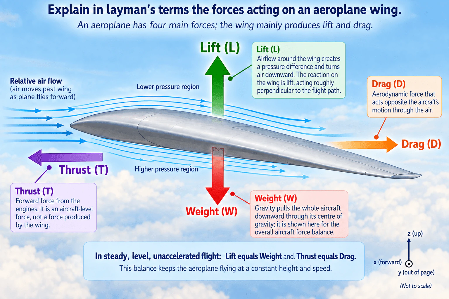
In layman's terms, think of an aeroplane as being pulled or pushed in four main directions. The wing mainly contributes two aerodynamic forces: lift and drag. The other two forces, weight and thrust, belong to the aircraft as a whole.

For a simple free-body description, define the +x direction as forward along the flight path and +z as upward. Relative airflow moves past the aircraft in the opposite direction to its forward motion.

Lift is the aerodynamic force acting approximately perpendicular to the relative airflow. In straight, wings-level flight, its main component is upward. Airflow around the wing creates a pressure distribution over its surfaces, and the wing also changes the momentum of the air by turning it downward. The resulting aerodynamic reaction contains the lift force.

Drag is the aerodynamic force acting approximately parallel to the relative airflow and opposite the aircraft's motion through the air. It comes from aerodynamic pressure effects and skin friction.

Weight is the gravitational force acting downward through the aircraft's centre of gravity. It is an aircraft-level force rather than a force produced by the wing.

Thrust is the propulsive force produced by the engines and acts generally forward. It is also an aircraft-level force rather than a force produced by the wing.

If we assume straight, steady, level, unaccelerated flight, the net external force is zero. The simplified force balance is therefore lift equals weight and thrust equals drag. If these forces do not balance, the aircraft accelerates. For example, if thrust exceeds drag, the aircraft tends to accelerate forward; if the upward force exceeds the downward force, it tends to accelerate upward.

Useful Questions to Ask the Interviewer
  • Do you want the conventional four-force balance for the whole aircraft, or the forces acting on the wing itself?
  • May I assume straight, steady, level, unaccelerated flight?
  • Do you want only a conceptual explanation, or should I also discuss the structural reactions where the wing joins the fuselage?

For the wing alone, the important external loads include the distributed aerodynamic lift and drag plus structural reactions at the wing attachment. For the whole aircraft, the conventional simplified model uses lift, weight, thrust, and drag.
Explain in layman's terms the forces acting on an aeroplane wing. diagram
How to Explain It in an Interview

Start with the four-force picture: lift up, weight down, thrust forward, and drag backward for the simple straight-and-level case. Then clarify that the wing mainly creates lift and drag, while gravity provides weight and the engines provide thrust. Explain lift using both pressure distribution and downward turning of the airflow rather than relying on a single oversimplified cause. Finish by stating the assumption behind the balance: in steady, level, unaccelerated flight, lift equals weight and thrust equals drag.

Technical Approach
  1. Choose the free-body boundary: use the whole aircraft for the standard four-force explanation, or isolate the wing if the question is specifically about wing loads.
  2. Define coordinates: +x forward along the flight path and +z upward; relative airflow is opposite +x.
  3. Identify the external forces: lift, drag, weight, and thrust for the whole-aircraft model.
  4. State the operating assumption: straight, steady, level, unaccelerated flight if using an equilibrium balance.
  5. Apply Newton's second law. With zero acceleration, the vector sum of external forces is zero.
  6. Resolve the forces by direction: lift balances weight vertically and thrust balances drag longitudinally in the simplified steady-level case.
  7. If the aircraft is climbing, turning, descending, or accelerating, use the full equations of motion instead of assuming pairwise balance.
Practical Insights

The four-force model is a useful first explanation, but real aircraft loading is more complicated. Lift and drag vary with airspeed, air density, angle of attack, wing geometry, configuration, and manoeuvre state. Lift is defined relative to the airflow, not simply as 'vertical' in every flight condition. During climbs, turns, gusts, or acceleration, the forces may not balance. The wing also carries distributed aerodynamic loads that create structural shear forces and bending moments, but those details are beyond the scope of this introductory question.

Why Interviewers Ask This

Interviewers want to see whether you can identify the important external forces, apply a simple free-body-diagram approach, state the assumptions behind equilibrium, and explain basic aircraft mechanics accurately in language that a non-specialist can understand.

Common interview mistakes

Common mistakes include saying that the wing produces all four forces, reversing thrust and drag, treating weight as an aerodynamic force, or claiming that lift is caused only by faster air over the top of the wing. Another common mistake is saying that lift always acts vertically; more precisely, aerodynamic lift is defined approximately perpendicular to the relative airflow. It is also incorrect to state that lift equals weight and thrust equals drag without first assuming steady, level, unaccelerated flight.

Interview tip

Define the flight direction and assumptions first, then give the simple four-force picture. A strong concise explanation is: lift up, weight down, thrust forward, drag backward in straight level flight; the wing mainly creates lift and drag, gravity creates weight, and the engines create thrust. Then state that the forces balance only in steady, level, unaccelerated flight.
Interviewer may ask next
How would you check whether lift equals weight and thrust equals drag is a valid assumption?

First confirm that the aircraft is in straight, steady, level, unaccelerated flight. If speed, altitude, or direction is changing, there is acceleration and the forces do not generally balance pairwise. The correct check is Newton's second law: the vector sum of the external forces must equal mass times acceleration. When acceleration is zero and the flight path is level, the simplified balances lift equals weight and thrust equals drag are appropriate.
What changes if the aircraft starts climbing, turning, or accelerating?

The simple pairwise balance no longer necessarily applies. The force vectors must be resolved along suitable axes and Newton's second law applied in each direction. In a climb, weight has components relative to the flight path. In a turn, lift is tilted and must provide both vertical support and the force needed to change direction. During acceleration, the net force is non-zero.

2. What affects the thermal properties of a composite material?NEWMaterials And Material SelectionMediumRolls Royce

Short Interview Answer (30-60 seconds)

The thermal properties of a composite are controlled by both its constituent materials and its internal structure. Important factors are the thermal properties of the fibre and matrix, fibre volume fraction, fibre orientation and laminate lay-up, fibre–matrix interfaces and defects such as voids, and the matrix chemistry and degree of cure. Temperature, moisture, and ageing also affect the response. Therefore properties such as thermal conductivity and thermal expansion are often direction-dependent rather than represented by one isotropic value.

Detailed Explanation

A composite's thermal behavior comes from the combined response of its reinforcement, matrix, interfaces, and internal architecture. For a fibre-reinforced polymer laminate, I would not quote one thermal conductivity or expansion coefficient without first defining the material system, direction, temperature range, and environment.

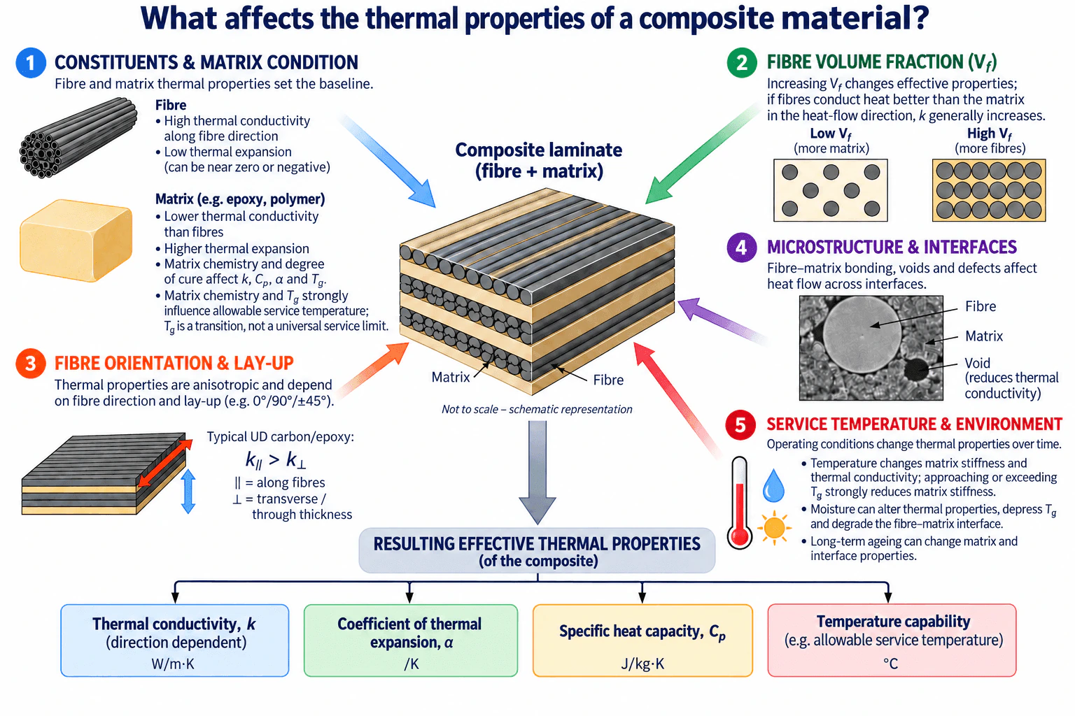
The first factor is the constituents and matrix condition. The fibre and matrix each have their own thermal conductivity k, coefficient of thermal expansion α, specific heat capacity Cp, and temperature-dependent behavior. In a typical unidirectional carbon-fibre/polymer composite, heat conduction can be greater along the fibres than transverse to them, while the fibre and matrix can also have very different thermal expansion behavior. Matrix chemistry and degree of cure can influence k, Cp, α, and glass-transition temperature Tg. Tg is a material transition rather than a universal maximum service-temperature limit, although it strongly influences the allowable operating range of a polymer-matrix composite.

The second factor is fibre volume fraction, Vf. Changing Vf changes how strongly the reinforcement and matrix contribute to the effective properties. If the fibres have higher thermal conductivity than the matrix in the direction of heat flow, increasing Vf will generally increase effective conductivity in that direction. The exact result also depends on orientation, microstructure, interfaces, and the constituent properties.

The third factor is fibre orientation and lay-up. Composite laminates are often anisotropic. For a typical unidirectional carbon/epoxy laminate, the conductivity along the fibres, k∥, is greater than the transverse conductivity, k⊥. A laminate containing 0°, 90°, and ±45° plies therefore has different directional thermal behavior from a laminate dominated by one fibre direction. Thermal expansion is also direction-dependent because the fibres constrain the matrix differently along and across the reinforcement direction.

The fourth factor is microstructure and interfaces. Fibre–matrix bonding, interfacial thermal resistance, porosity, voids, cracks, and other defects affect heat transfer. Interfaces can add resistance to heat flow, and voids typically disrupt an otherwise continuous heat-transfer path. This means measured laminate properties can differ from simple idealized mixture estimates.

The fifth factor is service temperature and environment. Thermal conductivity and matrix properties can vary with temperature. For polymer-matrix composites, approaching or exceeding Tg can strongly reduce matrix stiffness. Moisture can alter thermal properties, reduce Tg in susceptible polymer systems, and contribute to degradation of the fibre–matrix interface. Long-term ageing and repeated environmental exposure can also change matrix and interface properties.

The resulting effective properties I would evaluate are thermal conductivity k in W/(m·K), coefficient of thermal expansion α in 1/K, specific heat capacity Cp in J/(kg·K), and allowable temperature capability in °C for the defined service condition. Because a composite can be anisotropic, these properties should be reported with the relevant material direction and test condition.

Useful Questions to Ask the Interviewer
  • What fibre and matrix system are we considering?
  • Is heat flow mainly along the fibres, transverse to them, or through the laminate thickness?
  • What are the steady-state and transient operating temperatures?
  • Will the component experience moisture, thermal cycling, oxidation, or another environmental exposure?
  • Which property is most important: conductivity, thermal expansion, heat capacity, temperature capability, or a combination?
  • Are measured laminate data available, or are we estimating properties during early-stage material selection?
What affects the thermal properties of a composite material? diagram
How to Explain It in an Interview

I would organize the answer around five influences: constituents and matrix condition, fibre volume fraction, fibre orientation and lay-up, microstructure and interfaces, and service temperature and environment. I would emphasize that composites are commonly anisotropic, using a typical unidirectional carbon/epoxy laminate as an example where k∥ is greater than k⊥. I would then connect those factors to the effective outputs: thermal conductivity, thermal expansion, specific heat capacity, and temperature capability. Finally, I would say that important design values should be validated using traceable laminate data or testing at representative temperature, moisture condition, material state, and fibre direction.

Technical Approach
  1. Define the required effective thermal properties: k, α, Cp, and/or temperature capability.
  2. Define the material axes, heat-flow direction, operating temperature range, and environment.
  3. Identify the fibre and matrix and obtain traceable constituent or laminate property data under comparable conditions.
  4. Record fibre volume fraction Vf and the fibre orientations or laminate stacking sequence.
  5. Account for matrix chemistry, degree of cure, Tg, and other relevant material-condition effects.
  6. Examine microstructural effects such as interfaces, porosity, voids, cracks, and defects.
  7. Estimate or compare directional effective properties using an appropriate composite model while stating its assumptions and limitations.
  8. Evaluate how temperature, moisture, ageing, and thermal cycling may change the properties.
  9. Compare candidate materials using the same directions, environmental conditions, units, and reference temperatures.
  10. Validate important design values using representative laminate data or physical testing when the decision is performance- or safety-critical.
Practical Insights

The main tradeoff is that changing the composite architecture to improve one thermal property can affect others. More high-conductivity reinforcement may improve conductivity in the fibre direction without producing the same benefit through the thickness. Changing the lay-up can make the response more balanced between directions but reduce the maximum property in one preferred direction. A matrix with greater temperature capability may also change processing requirements, cost, toughness, environmental resistance, or service life. Voids and imperfect interfaces can increase thermal resistance and uncertainty. For final material selection, measured laminate properties under representative conditions are more reliable than assuming ideal constituent behavior.

Why Interviewers Ask This

Interviewers want to see whether I understand that a composite does not have one universal set of thermal properties. Its effective thermal behavior depends on the constituent materials, their proportions and orientation, the fibre–matrix interfaces and defects, the matrix condition, and the service environment. They are also testing whether I recognize anisotropy and can connect material structure to thermal conductivity, thermal expansion, specific heat capacity, and temperature capability.

Common interview mistakes

Common mistakes are treating the composite as isotropic; quoting one thermal conductivity without specifying direction; assuming higher fibre content always increases conductivity regardless of the relative fibre and matrix conductivities and heat-flow direction; treating Tg as an absolute universal service-temperature limit; ignoring matrix cure state, interfaces, porosity, and voids; using constituent values as though they were measured laminate properties; and comparing data measured at different temperatures, moisture conditions, or material states.

Interview tip

Organize the answer around the same five factors shown in the material model: constituents and matrix condition, fibre volume fraction, orientation and lay-up, microstructure and interfaces, and service temperature and environment. Mention anisotropy early and use k∥ > k⊥ for a typical unidirectional carbon/epoxy laminate as an example, while making clear that actual values depend on the specific constituent materials, architecture, and operating conditions.

Interviewer may ask next
How would you validate the thermal properties selected for a composite component?

I would first confirm that the data corresponds to the actual fibre, matrix, fibre volume fraction, lay-up, cure state, test direction, temperature, and moisture condition. For an important design, I would then test representative laminate coupons or components using an appropriate thermal-property method. I would measure directional properties where anisotropy matters and repeat testing at relevant service temperatures and environmental conditions. I would compare those measurements with the analytical or micromechanics estimate, investigate significant differences such as void or interface effects, and use the validated laminate data for the final material decision.

What changes if the composite must operate at a much higher temperature?

Temperature capability becomes a stronger selection constraint. I would examine how matrix stiffness, Tg, thermal conductivity, thermal expansion, oxidation or environmental resistance, and long-term ageing change over the required temperature range. If the polymer matrix approaches a temperature region where its properties degrade too much, I would consider a higher-temperature polymer system or another composite family. I would then compare reinforcement compatibility, processing requirements, thermal cycling behavior, cost, and service life using properties measured or qualified at the actual operating temperature rather than relying only on room-temperature values.

3. Describe how a jet engine works.NEWThermodynamics And Heat TransferEasyRolls Royce

Short Interview Answer (30-60 seconds)

A modern turbofan draws air through the inlet and fan. The fan accelerates a bypass stream around the core while some air enters the compressor, where its pressure and temperature rise. Fuel is then added and burned in the combustor, increasing the gas energy. The hot gases expand through the turbine, which extracts shaft work to drive the compressor and fan. The remaining core-gas energy is converted into velocity through the nozzle. The rearward acceleration of both bypass air and core exhaust creates forward thrust.

Detailed Explanation

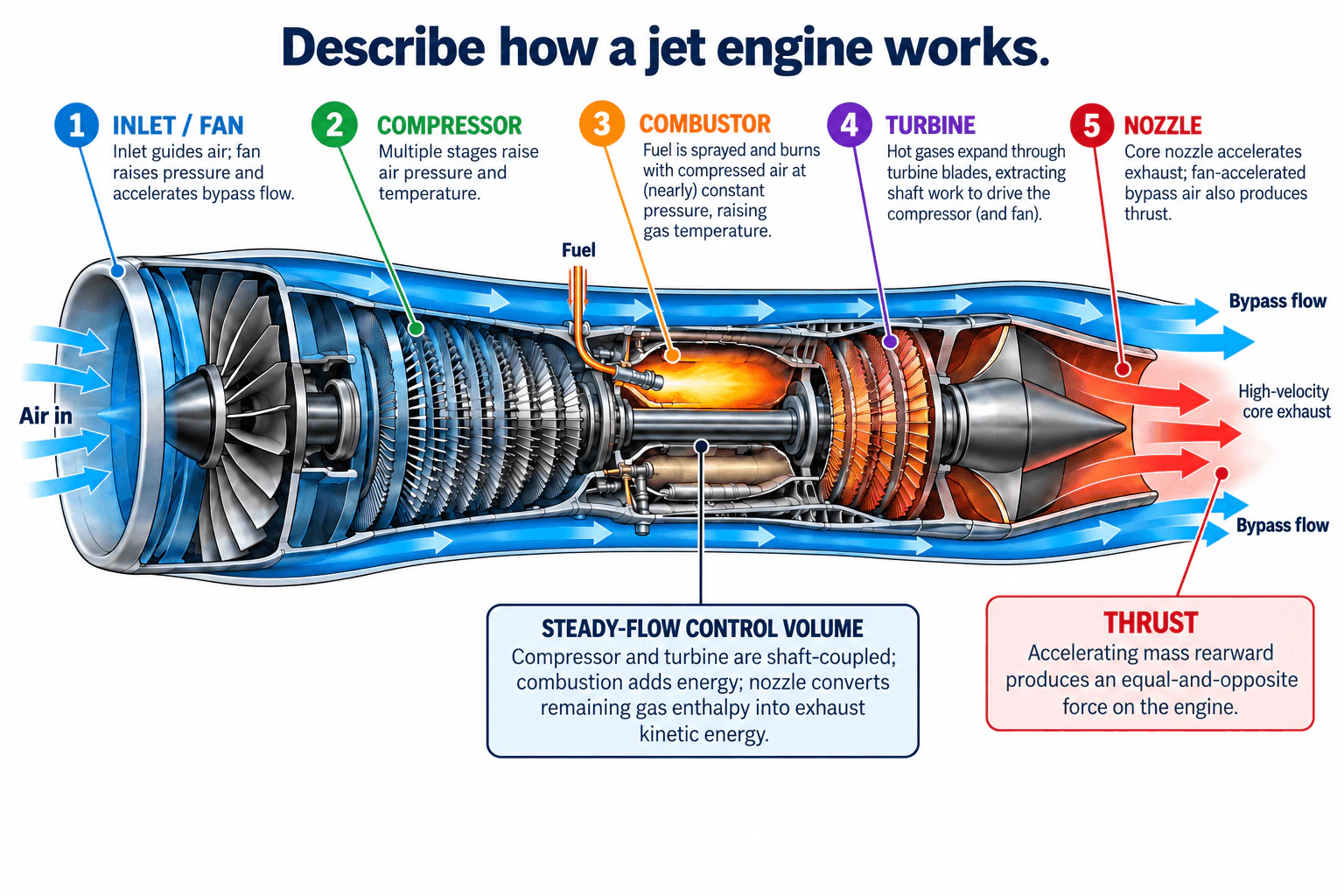
A modern turbofan can be explained as a steady-flow control volume with air and fuel entering and bypass air plus core exhaust leaving.

The flow begins at the inlet and fan. The inlet guides incoming air into the engine. The fan raises the pressure of the incoming flow and accelerates a large bypass stream around the engine core. The rest of the air enters the core compressor.

The compressor uses shaft work to raise the core air pressure and temperature. This prepares the air for efficient combustion.

Fuel is then injected into the combustor and burned with the compressed air. In the real engine, chemical energy carried by the fuel is released into the flowing gas. In an ideal Brayton-cycle model, this is commonly represented as heat addition at approximately constant pressure. A real combustor has a finite pressure loss.

The hot, high-energy gas expands through the turbine. The turbine extracts part of the gas enthalpy and converts it into shaft work. Through one or more mechanically coupled shafts or spools, that work drives the compressor and the fan. The turbine therefore removes enough energy from the hot gas to keep the upstream rotating machinery operating.

After the turbine, the core gas still has useful enthalpy and pressure. The core nozzle converts much of that remaining energy into exhaust kinetic energy, so the gas leaves at high rearward velocity. At the same time, the fan-accelerated bypass stream also exits rearward and contributes to thrust.

The energy conversion can be summarized with the steady-flow first law. For a single component, using heat transfer into the control volume as positive and shaft work out as positive:

Q̇ - Ẇs = ṁ[(h2 - h1) + (V2² - V1²)/2 + g(z2 - z1)]

where Q̇ is heat-transfer rate in watts, Ẇs is shaft-power rate in watts, ṁ is mass-flow rate in kilograms per second, h is specific enthalpy in joules per kilogram, V is velocity in meters per second, g is gravitational acceleration in meters per second squared, and z is elevation in meters. Potential-energy changes are usually negligible for this conceptual engine explanation. For the complete turbofan, the control-volume balance must account for the separate core and bypass mass flows and the incoming fuel.

Thrust follows from conservation of momentum. The engine accelerates mass rearward, and the reaction force on the engine is forward. A complete thrust calculation includes the momentum changes of both the core and bypass streams and, when exhaust pressure differs from ambient pressure, a pressure-thrust term.

Useful Questions to Ask the Interviewer
  • Do you want a general gas-turbine explanation or specifically a modern turbofan? A turbofan explanation should include both the core and bypass streams.
  • Should I keep the answer conceptual, or include the Brayton-cycle and control-volume energy balance?
  • Should I assume steady operating conditions? For a basic thermodynamic explanation, steady flow is the usual starting assumption.
Describe how a jet engine works. diagram
How to Explain It in an Interview

Follow the air in order: inlet and fan, compressor, combustor, turbine, then nozzle. State the job of each component. The fan accelerates bypass air and feeds the core. The compressor raises core pressure. The combustor releases fuel energy into the gas. The turbine extracts shaft work to drive the compressor and fan. The nozzle converts remaining core-gas enthalpy into exhaust velocity. Finish by explaining that accelerating the bypass and core streams rearward produces forward thrust. That connects the physical engine layout directly to the first law of thermodynamics and momentum conservation.

Technical Approach
  1. Define the turbofan as a steady-flow control volume with incoming air and fuel and outgoing bypass air and core exhaust.
  2. Follow the flow from inlet and fan to compressor, combustor, turbine, and core nozzle.
  3. Identify the energy role of each component: the fan and compressor receive shaft work, combustion releases fuel chemical energy, the turbine extracts shaft work, and the nozzle converts remaining core-gas enthalpy into kinetic energy.
  4. Identify the mechanical coupling from turbine stages to the compressor and fan through the engine shafts or spools.
  5. Apply the steady-flow first law to check that the stated energy transfers are physically consistent.
  6. Apply momentum conservation to explain why rearward acceleration of the core and bypass streams produces forward thrust.
  7. Recognize real-engine departures from the ideal model, including compressor and turbine inefficiency, combustor pressure loss, mechanical losses, and nozzle losses.
Practical Insights

A turbofan must balance thermal efficiency, propulsive efficiency, component temperature limits, pressure ratio, mass flow, weight, drag, and mechanical complexity. A larger bypass flow allows the engine to produce thrust by accelerating more air through a smaller velocity increase, which is generally favorable for propulsive efficiency in subsonic flight. Higher compressor pressure ratio can improve ideal cycle efficiency, but it also increases compressor discharge temperature and places greater demands on the compressor, combustor, turbine, cooling system, and materials. Real components are not ideal, so pressure losses and inefficiencies reduce the useful energy available for thrust.

Why Interviewers Ask This

Interviewers want to see whether the candidate can explain a gas-turbine engine as a connected thermodynamic system: how air moves through the engine, how fuel energy is added, how the turbine powers the compressor and fan, and how accelerating the core and bypass streams rearward produces thrust.

Common interview mistakes

Common mistakes include saying that combustion is an explosion, saying pressure rises continuously through the entire engine, saying the turbine directly produces all of the thrust, forgetting that the turbine drives the compressor and fan, ignoring bypass airflow in a turbofan, or treating the nozzle as the only contributor to thrust. Another mistake is presenting the ideal Brayton cycle as an exact description of a real engine without acknowledging component inefficiencies and combustor pressure loss.

Interview tip

Explain the engine in the same direction that the air flows. Use one clear purpose for each stage, then connect the stages with two governing ideas: the first law explains the energy transfers, and momentum conservation explains why accelerating the bypass air and core exhaust rearward creates forward thrust.

Interviewer may ask next
What assumptions would you make for a simple thermodynamic analysis of the engine?

I would begin with steady-flow operation, negligible potential-energy change, and defined inlet and outlet states. For an ideal Brayton-cycle model, I would approximate compression and turbine expansion as adiabatic and isentropic and represent combustion as approximately constant-pressure heat addition. For a real engine, I would use compressor and turbine efficiencies, combustor pressure loss, mechanical efficiency, nozzle efficiency, and appropriate gas properties. For a turbofan, I would also model the core and bypass streams separately.

How does increasing bypass ratio affect turbofan performance?

Increasing bypass ratio sends more of the inlet air around the core. The fan can then produce a given amount of thrust by accelerating a larger mass flow through a smaller velocity increase, which generally improves propulsive efficiency for subsonic flight. The tradeoffs include a larger fan diameter, greater nacelle size and drag, added weight, installation constraints, and the need for turbine stages capable of supplying the fan power.

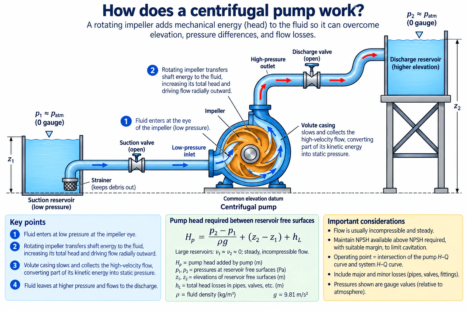
4. How does a centrifugal pump work?NEWFluid Mechanics And Fluid SystemsEasyRolls Royce

Short Interview Answer (30-60 seconds)

A centrifugal pump uses a rotating impeller to transfer shaft energy to a liquid. Fluid enters through the suction side at the impeller eye, the impeller increases the liquid's total head and drives it radially outward, and the volute casing collects the high-velocity flow and converts part of its kinetic energy into static pressure. The pump supplies enough head to overcome elevation differences, pressure differences, and losses in pipes, valves, fittings, and other restrictions. The actual flow rate is set by the intersection of the pump H-Q curve and the system H-Q curve, while adequate NPSH is needed to limit cavitation.

Detailed Explanation

A centrifugal pump is a rotodynamic machine that adds mechanical energy to a liquid. For the system shown, a reasonable starting assumption is steady, incompressible flow, such as water flowing between two large reservoirs.

Fluid first enters through the suction pipe and flows into the eye of the impeller at relatively low pressure. The impeller is connected to a rotating shaft. As the impeller rotates, its blades transfer shaft energy to the liquid, increasing the liquid's total head and driving the flow radially outward.

The liquid then enters the volute casing. The volute collects the flow leaving the impeller and slows part of that high-velocity flow as the passage area changes. This converts part of the liquid's kinetic energy into static pressure before the liquid leaves through the discharge pipe.

For the complete fluid system, the pump must provide enough head to overcome pressure differences, elevation differences, and hydraulic losses. Between two large reservoir free surfaces, where the free-surface velocities are approximately zero, the mechanical-energy equation can be written as:

H_p = (p_2 - p_1)/(rho g) + (z_2 - z_1) + h_L

where H_p is pump head added to the liquid in metres, p_1 and p_2 are pressures at the reservoir free surfaces in pascals, rho is fluid density in kg/m^3, g is gravitational acceleration in m/s^2, z_1 and z_2 are elevations in metres measured from the same datum, and h_L is the total head loss in metres from pipe friction and minor losses such as valves, bends, fittings, and the strainer.

If both reservoirs are open to the atmosphere, then p_1 and p_2 are approximately atmospheric pressure, or 0 gauge pressure. Their pressure-difference term is therefore approximately zero. The pump can still require substantial head because it must raise the liquid to the higher discharge-reservoir elevation and overcome flow losses.

The actual operating flow rate is not determined by the pump alone. The centrifugal pump has an H-Q curve showing the head it produces at different flow rates. The piping system also has an H-Q curve based on static head and flow-dependent losses. With no active control changing those relationships, the operating point occurs where the pump curve and system curve intersect.

Cavitation is another important constraint. As liquid approaches the impeller eye, its pressure can fall. If the local absolute pressure approaches or falls below the liquid's vapor pressure, vapor bubbles can form and then collapse as pressure recovers. The net positive suction head available, NPSHA, should therefore remain above the pump's required NPSH, NPSHR, with a suitable margin for the application.

Useful Questions to Ask the Interviewer
  • What liquid is being pumped, and can it be treated as incompressible?
  • Are the suction and discharge reservoirs open to atmosphere or pressurized?
  • What are the suction and discharge elevations relative to a common datum?
  • What flow rate is required?
  • What major and minor losses are expected in the pipes, valves, fittings, and strainer?
  • Is the pump H-Q curve available for checking the operating point?
  • What suction conditions and fluid vapor pressure are available for evaluating NPSH?
How does a centrifugal pump work? diagram
How to Explain It in an Interview

I would explain it in four steps. First, liquid enters the eye of the impeller through the suction side at relatively low pressure. Second, the rotating impeller transfers shaft energy to the liquid, increasing its total head and driving it radially outward. Third, the volute casing collects the high-velocity liquid and converts part of its kinetic energy into static pressure. Fourth, the pump's added head drives the liquid through the discharge system while overcoming elevation, pressure differences, and hydraulic losses.

I would then connect the pump to the system by stating that the real operating flow occurs where the pump H-Q curve intersects the system H-Q curve. Finally, I would mention that NPSH available must remain above NPSH required, with suitable margin, to limit cavitation. That gives both the internal working principle and the practical system-level behavior.

Technical Approach
  1. Define the fluid and operating assumptions, such as steady, incompressible liquid flow.
  2. Identify the suction and discharge reference locations and measure elevations from one common datum.
  3. Trace the energy transfer through the pump: liquid enters the impeller eye, the rotating impeller adds total head, and the volute converts part of the velocity energy into static pressure.
  4. Apply the mechanical-energy equation including pressure difference, elevation difference, and total major and minor head losses.
  5. Build or identify the system H-Q relationship.
  6. Compare the system H-Q curve with the pump H-Q curve to find the operating point.
  7. Check suction conditions by comparing NPSH available with NPSH required and maintaining a suitable margin.
  8. Validate that the resulting flow, head, pressures, and operating conditions are physically consistent.
Practical Insights

The main engineering tradeoff is between flow rate and head. As flow increases, pipe friction and minor losses usually increase, so the system requires more head. A centrifugal pump also has a limited useful operating range, and moving far from the intended operating region can reduce efficiency and reliability. Higher suction losses or higher fluid vapor pressure reduce cavitation margin. Partially closing a discharge valve increases system resistance and shifts the operating point to a lower flow rate.

Why Interviewers Ask This

Interviewers want to check whether you understand how a centrifugal pump transfers mechanical energy to a liquid and how that pump interacts with the complete fluid system. A strong answer should connect the impeller, volute casing, pump head, elevation, pressure difference, hydraulic losses, pump-system operating point, and cavitation margin.

Common interview mistakes

Common mistakes include saying that the pump creates flow independently of the piping system, treating pressure and head as identical, ignoring elevation and hydraulic losses, applying ideal Bernoulli without a pump-head term, measuring z_1 and z_2 from different reference datums, confusing gauge pressure with absolute pressure, assuming an elevated open reservoir has positive gauge pressure at its free surface, and ignoring cavitation. Another mistake is quoting a pump's nominal flow without checking where its H-Q curve intersects the system H-Q curve.

Interview tip

Start with the energy path: shaft energy goes into the impeller, the impeller raises the liquid's total head, and the volute converts part of the velocity energy into static pressure. Then connect the pump to the complete system by mentioning elevation, pressure difference, hydraulic losses, the pump-system operating point, and NPSH. That keeps the answer simple while still showing practical engineering judgment.

Interviewer may ask next
Why is NPSH important in a centrifugal pump?

Pressure can fall as the liquid approaches the impeller eye. If the local absolute pressure reaches or drops below the liquid's vapor pressure, vapor bubbles can form. Those bubbles can collapse as pressure recovers, causing cavitation, noise, vibration, loss of performance, and possible erosion. The system should therefore provide NPSH available above the pump's NPSH required, with a suitable margin for the application.

What happens if the discharge valve is partially closed?

Partially closing the discharge valve increases the system resistance and therefore increases the head loss at a given flow rate. The system H-Q curve shifts so that its intersection with the pump H-Q curve moves to a lower flow rate and typically a higher pump head. The exact new operating point depends on the shapes of the pump and system curves.

5. How does a turbomachine work?NEWFluid Mechanics And Fluid SystemsEasyRolls Royce

Question Details

Discuss its types and applications.

Short Interview Answer (30-60 seconds)

A turbomachine exchanges energy between a continuously flowing fluid and a rotating shaft. Its rotor blades change the fluid's velocity and angular momentum, producing torque. If the fluid drives the rotor, the machine is a turbine and produces shaft power. If the shaft drives the rotor, as in a pump, fan, blower, or compressor, energy is added to the fluid. Turbomachines can have axial, radial, or mixed flow and are used in power generation, propulsion, pumping, ventilation, refrigeration, and industrial compression.

Detailed Explanation

A turbomachine is a rotating machine that transfers energy between a continuously flowing fluid and a shaft. The key physical idea is momentum change. As fluid passes through the rotor, the blades change the magnitude or direction of the fluid velocity, especially its tangential component. That change in angular momentum produces a torque between the fluid and rotor.

For steady operation, conservation of mass requires the mass flow rate entering and leaving the machine to be consistent. The energy transferred to or from the rotor is described by the Euler turbomachinery relation:

Δh₀ = U₂Vθ₂ - U₁Vθ₁

where Δh₀ is the change in stagnation enthalpy per unit mass, U is blade speed, Vθ is the tangential component of absolute fluid velocity, and subscripts 1 and 2 identify rotor inlet and outlet. The equation shows that shaft-work transfer comes from changing the fluid's angular momentum.

The first major classification is based on the direction of energy transfer.

  • In a turbine, energy flows from the fluid to the shaft. The fluid loses available energy while producing rotor torque and shaft power. Examples include hydraulic, steam, and gas turbines.
  • In a pump, fan, blower, or compressor, energy flows from the shaft to the fluid. An external motor or engine turns the rotor, and the fluid gains mechanical or thermodynamic energy.

For an incompressible liquid such as water, a pump commonly increases pressure or head. Hydraulic power transferred to the liquid can be written as P_h = ρgQH, where ρ is fluid density in kg/m³, g is gravitational acceleration in m/s², Q is volumetric flow rate in m³/s, and H is the head rise in metres. For a real pump with efficiency η, the required shaft input is approximately P_shaft = ρgQH/η. For a hydraulic turbine, the shaft output is approximately P_shaft = ηρgQH. These expressions assume the stated head already represents the relevant mechanical-energy change across the machine.

For gases, especially when the pressure change is large, compressibility matters because density can change significantly. Compressors increase gas pressure by adding shaft work, while gas turbines extract shaft work as the gas expands. Absolute pressure, rather than gauge pressure, must be used when calculating thermodynamic pressure ratios.

A second classification is based on flow direction through the rotor.

  • Axial-flow machines move the fluid mainly parallel to the shaft. They are well suited to large flow rates and are common in aircraft compressors, turbines, and large fans.
  • Radial-flow machines move the fluid substantially toward or away from the shaft axis. Centrifugal pumps and centrifugal compressors are common examples.
  • Mixed-flow machines combine axial and radial motion.

Some turbomachines are also described as impulse or reaction machines. In an impulse stage, much of the pressure change occurs before the rotor and the rotor is driven mainly by a change in fluid momentum. In a reaction stage, pressure changes through the rotor as well as through stationary passages. The exact arrangement depends on the machine design.

Real machines operate with losses, so their actual performance is lower than the ideal energy transfer. Viscous effects, boundary-layer losses, separation, leakage, and mechanical losses can reduce efficiency. The relevant operating limits depend on machine type.

For a liquid pump, the actual flow rate is not determined by the pump alone. The operating point occurs where the pump curve intersects the system curve. The system curve includes static elevation and pressure requirements together with major pipe friction and minor losses from fittings, valves, and other components. The suction condition must also be checked using absolute pressure and net positive suction head to maintain an adequate cavitation margin.

For compressors and some other gas turbomachines, aerodynamic operating limits can include stall, surge, and choking. These effects mean that a machine should be operated within its validated performance map rather than assuming that any combination of pressure and flow is achievable.

Typical applications include hydraulic turbines for extracting energy from water, steam and gas turbines for producing shaft power, pumps for transporting liquids, fans and blowers for moving gases, compressors for process and refrigeration systems, and turbomachinery stages in propulsion systems.

Useful Questions to Ask the Interviewer
  • Are we discussing a turbine, pump, fan, blower, or compressor? The direction and form of energy transfer depend on the machine.
  • Is the working fluid a liquid or a gas? This determines whether constant density is a reasonable assumption or compressibility must be considered.
  • Should I explain only the basic operating principle, or also discuss performance quantities such as head, pressure ratio, efficiency, cavitation, and operating limits?
How to Explain It in an Interview

Start with the central idea: a turbomachine exchanges energy between a flowing fluid and a rotating shaft by changing the fluid's angular momentum. Then explain the energy direction. A turbine takes energy from the fluid and produces shaft work, while a pump, fan, blower, or compressor receives shaft work and adds energy to the fluid. Next, distinguish axial, radial, and mixed-flow arrangements. If more detail is useful, mention that liquid pumps are commonly described using flow rate and head, while compressible-gas machines are often described using mass flow and pressure ratio. Finish with a practical operating consideration such as pump-system curve matching and cavitation for pumps, or surge and choking limits for compressors.

Technical Approach
  1. Identify the working fluid and decide whether density can reasonably be treated as constant or whether compressibility is important.
  2. Identify the direction of energy transfer: fluid to shaft for a turbine, or shaft to fluid for a pump, fan, blower, or compressor.
  3. Define a control volume around the turbomachine and identify inlet, outlet, shaft-work direction, reference pressures, elevations, and steady or unsteady operating assumptions.
  4. Apply conservation of mass to establish a consistent mass flow rate.
  5. Use the change in fluid angular momentum, represented by the Euler turbomachinery relation when appropriate, to explain torque and shaft-work transfer.
  6. For incompressible liquid systems, relate the energy transfer to pressure, velocity, elevation, and head, including major and minor system losses where relevant.
  7. For compressible gas systems, use absolute pressure and consider changes in density, temperature, mass flow, and pressure ratio.
  8. Account for real efficiency and losses instead of assuming ideal energy transfer.
  9. Check machine-specific operating constraints, such as pump-system curve matching and cavitation margin for liquid pumps or surge, stall, and choking limits for applicable gas machines.
  10. Validate the operating point against appropriate manufacturer or test performance data before applying the result to real equipment.
Practical Insights

The main tradeoff is between how much energy the machine transfers and the losses or operating limits that accompany that transfer. Higher flow, head, pressure rise, or shaft power may require different rotor geometry, greater rotational speed, more stages, or a larger machine. Axial machines are attractive for high flow rates, while radial machines can provide substantial pressure or head change in compact arrangements. Real machines have an efficient operating range rather than one performance level at every flow rate. Pumps operated far from their intended operating point may become inefficient and experience undesirable hydraulic behavior, while inadequate suction pressure can lead to cavitation. Gas compressors have additional limits such as surge, stall, or choking depending on design and operating condition.

Why Interviewers Ask This

Interviewers want to verify that the candidate understands the basic fluid-mechanical principle of a turbomachine: energy transfer through a change in fluid momentum caused by rotating blades. They also want the candidate to distinguish energy-producing turbines from energy-absorbing pumps, fans, blowers, and compressors, recognize common flow configurations, and connect those principles to practical engineering applications.

Common interview mistakes

Common mistakes include saying that every turbomachine increases pressure; confusing turbines with pumps or compressors; describing only pressure change while ignoring the underlying change in angular momentum; confusing turbomachines with positive-displacement machines; assuming a gas is incompressible when its density changes significantly; using gauge pressure in a thermodynamic pressure ratio that requires absolute pressure; applying ideal Bernoulli without including shaft work and losses; assuming a pump has one fixed flow rate without considering the system curve; and discussing a liquid pump without checking cavitation risk and suction conditions.

Interview tip

Lead with the energy exchange and momentum principle rather than only listing machine types. Say that rotating blades change the fluid's angular momentum, creating torque. Then distinguish turbine operation from pump, fan, blower, and compressor operation, mention axial or radial flow, and give practical applications. For a stronger answer, add one realistic operating constraint such as efficiency, pump-system matching, cavitation, surge, or choking.

Interviewer may ask next
How would you verify that a centrifugal pump is operating correctly in a real fluid system?

I would first define the fluid properties, expected flow range, inlet and outlet locations, pressure reference, elevation difference, and whether operation is steady. I would measure or obtain the actual flow rate and inlet and outlet pressures, then use the mechanical-energy equation to determine the actual pump head, including velocity and elevation terms where significant. I would compare that operating point with the pump performance curve and the system curve, which should include static requirements, Darcy-Weisbach pipe losses, and relevant minor losses. On the suction side, I would use absolute pressure and calculate the available net positive suction head, then compare it with the required value using the appropriate engineering margin to assess cavitation risk. I would also compare power, efficiency, vibration, noise, and other relevant measured behavior with approved manufacturer or test data rather than relying only on an ideal calculation.

How does the analysis change when the turbomachine handles a compressible gas instead of an incompressible liquid?

For a compressible gas, I would not generally assume constant density when the pressure change is significant. I would work with mass flow rate and use absolute inlet and outlet pressures, pressure ratio, temperature, and energy change across the machine. In a compressor, shaft work increases the gas energy and normally raises both pressure and temperature. In a gas turbine, the gas expands and transfers energy to the rotor, producing shaft work. The performance description therefore depends more strongly on thermodynamic state as well as fluid momentum. I would also check the applicable aerodynamic operating limits, such as surge or stall in compressors and choking where local flow reaches its limiting condition.

6. Explain the Euler turbine equation.NEWFluid Mechanics And Fluid SystemsMediumRolls Royce

Short Interview Answer (30-60 seconds)

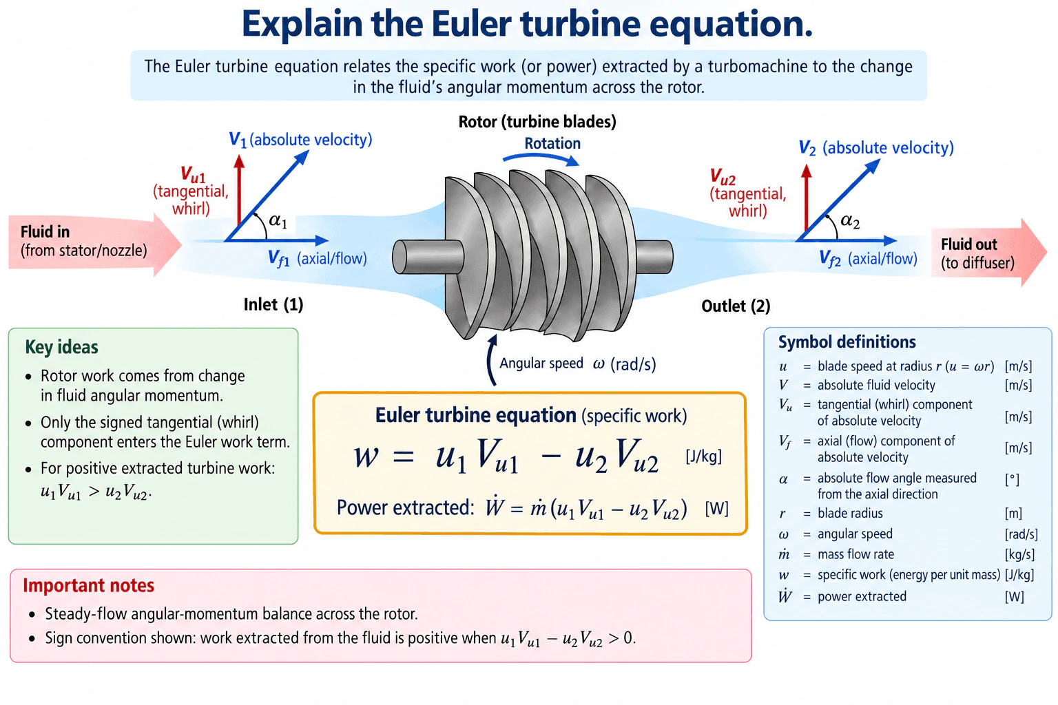
The Euler turbine equation relates the specific work extracted from a flowing fluid to its change in angular momentum across a rotating rotor. Using the turbine sign convention shown, w = u1Vu1 - u2Vu2, where u is blade peripheral speed and Vu is the signed tangential, or whirl, component of absolute fluid velocity. The corresponding extracted power is Wdot = mdot(u1Vu1 - u2Vu2). Therefore, positive turbine work requires u1Vu1 > u2Vu2.

Detailed Explanation

The Euler turbine equation is the fundamental work-transfer relation for turbomachinery. For a turbine, it expresses the shaft work extracted from the fluid in terms of the change in the fluid's angular momentum across the rotor.

Using the sign convention shown in the diagram, the specific work extracted from the fluid is

w = u1Vu1 - u2Vu2

and the corresponding extracted power is

Wdot = mdot(u1Vu1 - u2Vu2).

Here, w is specific work in J/kg, Wdot is power in W, mdot is mass flow rate in kg/s, u is blade peripheral speed in m/s, and Vu is the signed tangential, or whirl, component of the absolute fluid velocity in m/s. Blade speed is

u = omega r,

where omega is angular speed in rad/s and r is blade radius in m.

The absolute fluid velocity V can be resolved into an axial, or flow, component Vf and a tangential, or whirl, component Vu. In the diagram, Vf1 and Vf2 are aligned with the machine axis, while Vu1 and Vu2 are perpendicular to that axis. The flow angle alpha is measured from the axial direction.

The physical basis is the steady-flow angular-momentum balance for a control volume around the rotor. A change in the fluid's tangential momentum produces torque on the rotor. Multiplying that torque by angular speed gives the shaft power, which leads to the Euler turbine equation.

For the stated turbine sign convention, positive work extraction requires

u1Vu1 - u2Vu2 > 0,

or equivalently

u1Vu1 > u2Vu2.

This is the general condition. It is more accurate than simply saying that Vu2 must be smaller than Vu1 because the blade speeds u1 and u2 can differ if the inlet and outlet radii are different.

The Euler relation applies to steady turbomachinery flow using consistently defined inlet and outlet conditions and signed velocity components. It is not restricted to incompressible flow; the same angular-momentum principle can be applied to compressible turbomachinery. However, the equation by itself does not determine the velocity triangles or account separately for aerodynamic loss, leakage, disc friction, bearing loss, or other real-machine effects. Those effects influence the actual flow field and measured shaft performance and must be considered when validating a real turbine.

A useful units check is

uVu = (m/s)(m/s) = m^2/s^2 = J/kg,

so multiplying by mdot in kg/s gives power in J/s = W.

Useful Questions to Ask the Interviewer
  • Should I use the convention that positive w means work extracted from the fluid by the turbine?
  • Are the inlet and outlet radii the same, so u1 = u2, or should I keep the general u1 and u2 terms?
  • Should I treat the inlet and outlet velocity components as representative mean values across each station?
  • Do you want only the physical explanation, or should I also derive the equation from angular momentum and discuss the velocity triangles?
Explain the Euler turbine equation. diagram
How to Explain It in an Interview

Start with the physical idea: a turbine extracts shaft work by reducing the fluid's angular momentum through the rotor. Then define the velocity components. The absolute velocity V is resolved into an axial component Vf and a signed tangential component Vu. The tangential component is the one that enters the angular-momentum and Euler work terms.

Next write the general turbine form:

w = u1Vu1 - u2Vu2.

Define u = omega r and explain that u1 and u2 may differ if the rotor inlet and outlet are at different radii. Then multiply by mass flow rate to obtain power:

Wdot = mdot(u1Vu1 - u2Vu2).

State the sign convention explicitly: positive extracted turbine work requires u1Vu1 > u2Vu2. The signs of Vu1 and Vu2 must therefore be retained rather than using only their magnitudes.

Finally, check the units and connect the equation to practice. The Euler relation tells you the work transfer associated with the measured or calculated velocity triangles. For a real turbine, I would verify the velocity components, radii, angular speed, mass flow rate, torque, and shaft power, then account separately for losses and measurement uncertainty before judging machine performance.

Technical Approach
  1. Define a steady control volume around the rotor with inlet station 1 and outlet station
  2. 2. Choose the positive rotational and tangential directions so the signs of Vu1 and Vu2 are unambiguous.
  3. Resolve each absolute velocity into axial component Vf and signed tangential component Vu.
  4. Determine the blade peripheral speeds from u1 = omega r1 and u2 = omega r2.
  5. Apply the steady-flow angular-momentum balance to relate the change in fluid angular momentum to rotor torque.
  6. Use the turbine form of the Euler equation, w = u1Vu1 - u2Vu2.
  7. Calculate extracted power from Wdot = mdot w.
  8. Check that uVu has units of J/kg and that Wdot has units of W.
  9. Verify the sign convention and confirm that positive extracted work satisfies u1Vu1 > u2Vu2.
  10. For real equipment, compare the Euler work transfer with measured torque or shaft power and evaluate aerodynamic, leakage, mechanical, and measurement losses separately.
Practical Insights

The main physical tradeoff is that changing the signed whirl component changes the ideal rotor work transfer, but the required velocity triangles must still be achievable without excessive aerodynamic loss, separation, leakage, or other real-machine penalties. If inlet and outlet radii differ, blade speed also changes, so the weighted terms uVu matter rather than whirl velocity alone. The Euler equation relates angular-momentum change to rotor work transfer, but it does not by itself provide turbine efficiency or predict every loss mechanism.

Why Interviewers Ask This

Interviewers use this question to assess whether you understand how a turbomachine exchanges energy with a fluid through angular momentum, whether you can interpret velocity triangles and signed whirl velocity correctly, and whether you can apply a consistent turbine sign convention instead of simply memorizing an equation.

Common interview mistakes

Common mistakes include reversing the turbine sign convention, using total velocity magnitude instead of the signed tangential component Vu, confusing the axial component Vf with the whirl component Vu, assuming u1 = u2 when the inlet and outlet radii differ, using Vu2 < Vu1 as the general work criterion without considering blade speed, measuring alpha from a different reference direction without stating it, dropping the signs of the whirl components, and assuming the Euler equation alone predicts all real turbine losses or efficiency.

Interview tip

Lead with the angular-momentum principle rather than only quoting the formula. State that the signed tangential velocity component drives the torque term, write w = u1Vu1 - u2Vu2 for the stated turbine convention, define u = omega r, and finish with the positive-work condition u1Vu1 > u2Vu2 and a quick units check.

Interviewer may ask next
What assumptions and validation checks would you make before applying the Euler turbine equation to real test data?

I would confirm that the operating point is sufficiently steady for a steady-flow analysis, define the inlet and outlet reference stations, establish the positive rotational and tangential directions, and use representative velocity components at those stations. I would verify r1, r2, omega, mdot, Vu1, and Vu2 with consistent SI units and retain the signs of the whirl components. I would then compare the predicted angular-momentum work transfer with measured torque or shaft power and investigate aerodynamic, leakage, mechanical, and measurement losses if they do not agree.

How does the Euler turbine equation simplify if the rotor inlet and outlet are at the same radius?

If r1 = r2 and the rotor has a single angular speed omega, then u1 = u2 = u. The equation becomes w = u(Vu1 - Vu2). For the stated sign convention, positive extracted turbine work therefore requires Vu1 > Vu2. The general form u1Vu1 - u2Vu2 should still be retained whenever the inlet and outlet radii differ.

7. Discuss your previous component design experience, or related turbomachinery experience.NEWMechanical DesignMediumRolls Royce

Question Details

Describe your own work in component design or a related turbomachinery area.

Short Interview Answer (30-60 seconds)

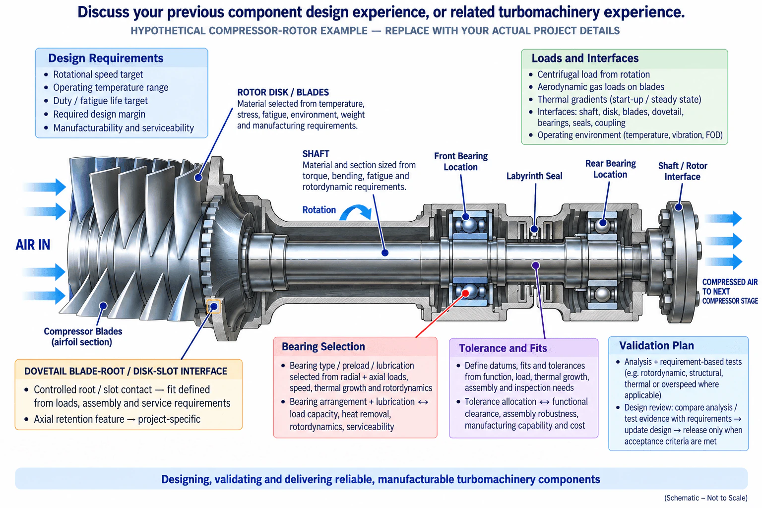
Because the exact details of your previous project are not supplied here, I would structure the answer around a real project you worked on using this compressor-rotor example as a guide. I would start with the rotational-speed target, operating-temperature range, fatigue-life target, design margin, environment, and interfaces. Then I would explain the centrifugal, aerodynamic, thermal, torque, and bending loads that drove the rotor disk, blades, shaft, bearings, seals, fits, and tolerances. I would describe the main material, manufacturability, assembly, serviceability, and reliability tradeoffs, then finish with how I validated the design through analysis, inspection, requirement-based testing, and design review before release.

Detailed Explanation

A strong answer should describe one real component or turbomachinery project from requirements through validation instead of listing tools or isolated tasks. Since no personal project details have been supplied here, the compressor-rotor example below is a structure to replace with your actual work.

I would begin by defining the component boundary and measurable design requirements. For a compressor-rotor example, the important inputs would include rotational-speed target, operating-temperature range, duty and fatigue-life target, required design margin, operating environment, manufacturability, and serviceability. I would also define the interfaces with the rotor disk, blades, blade-root attachment, shaft, bearings, labyrinth seal, and shaft or rotor connection. I would keep numerical values as project-specific unless they were actually known.

Next, I would identify the governing load cases and the load path. The blades experience centrifugal loading from rotation and aerodynamic gas loading. The rotor can also experience thermal gradients during start-up and steady operation. Those loads transfer through the blade-root and disk-slot interface into the rotor disk and shaft. The shaft must also be evaluated for transmitted torque, bending, fatigue, and rotordynamic behavior, with the bearing locations providing the primary rotor support.

For the rotor disk and blades, I would select material from the actual temperature, stress, fatigue, environment, weight, manufacturing, and inspection requirements rather than assuming a particular alloy. The shaft material and section would similarly be chosen from torque, bending, fatigue, stiffness, and rotordynamic requirements.

The blade-root and disk-slot interface is a critical local design area. In this example, the geometry is a dovetail-type attachment. I would evaluate contact loading, local stress concentration, fatigue, fretting risk, assembly method, inspection access, and the project-specific axial-retention feature. I would define the root-to-slot fit from load transfer, assembly needs, thermal growth, manufacturing capability, and service requirements rather than assuming a generic interference fit.

For the bearing system, I would first establish the required front and rear bearing locations. I would then select bearing type, arrangement, preload or internal-clearance strategy, and lubrication from radial and axial loads, shaft speed, thermal growth, stiffness, heat removal, rotordynamic behavior, and serviceability. I would also examine how the bearing arrangement affects shaft alignment and rotor motion.

The labyrinth-seal region would be treated as another functional interface. The design objective is to control leakage while allowing the rotor to operate without unintended rubbing under expected motion, tolerance variation, and thermal growth. Seal geometry and clearance therefore need to be considered together with rotor dynamics, manufacturing capability, assembly, and inspection.

Fits and tolerances would be allocated from function. I would establish datums and define the fits and tolerances needed for bearing mounting, shaft alignment, blade-root contact, seal clearance, assembly robustness, and inspection. I would avoid tightening every tolerance unnecessarily because tighter manufacturing control can increase cost, scrap risk, and assembly difficulty. Each critical tolerance should have a clear functional reason.

I would also apply design-for-manufacturing and design-for-assembly thinking while the geometry is still flexible. That means checking whether components can be produced and inspected consistently, whether blades, bearings, seals, and adjacent hardware can be assembled in a practical sequence, and whether service access allows inspection, removal, and replacement without unnecessary disruption.

I would use a failure-mode review to focus the design and validation effort. Examples for this type of assembly could include blade-root fretting or fatigue, excessive local disk stress, shaft fatigue, bearing overload or excessive heat, undesirable rotor vibration, seal rub from insufficient clearance, excessive leakage from excessive clearance, dimensional stack-up problems, or assembly damage. For each important failure mode, I would identify the cause, effect, prevention or detection method, and the evidence needed to show that the risk is controlled.

Validation would close the loop between the design assumptions and actual evidence. Depending on the component and program, that could include structural analysis, thermal analysis, rotordynamic assessment, dimensional inspection, material verification, balance checks, and requirement-based testing. Structural, thermal, rotordynamic, or overspeed tests could be used where applicable to the real requirements. I would compare the analysis and test evidence with the acceptance criteria, investigate discrepancies, update the design or assumptions, and repeat the review as necessary. I would not describe the component as ready for release simply because one simulation passed.

The main tradeoffs I would discuss are performance versus weight, durability versus mass, bearing stiffness versus heat generation and preload sensitivity, leakage control versus seal clearance and thermal growth, tolerance control versus manufacturing cost, and performance versus maintainability. These decisions are coupled, so I would explain how changing one part of the design affects the rest of the rotor system.

My conclusion would focus on engineering ownership: I started from requirements and interfaces, established the important load cases, made justified component and material decisions, considered manufacturing and serviceability, identified credible failure modes, and used analysis and test evidence to iterate the design before release. In an actual interview, I would replace this hypothetical structure with the component, decisions, problems, changes, and validation evidence from my own work.

Useful Questions to Ask the Interviewer
  • Which component or turbomachinery subsystem is most relevant to this role: rotors, shafts, bearings, seals, casings, or another area?
  • Is the team mainly interested in preliminary design, detailed design, analysis, manufacturing support, validation, or the complete lifecycle?
  • Which operating conditions usually dominate the design: rotational speed, temperature, fatigue duty, aerodynamic loading, vibration, or service life?
  • How much ownership does the mechanical designer have over interfaces with materials, manufacturing, test, suppliers, and service teams?
  • Are there particular design-review, drawing, tolerance, validation, or serviceability practices that are especially important for this role?
Discuss your previous component design experience, or related turbomachinery experience. diagram
How to Explain It in an Interview

Use a simple sequence: requirements → loads and interfaces → design decisions → failure risks and tradeoffs → validation and iteration. First, name the component and state exactly what you personally owned. Then explain the measurable requirements and interfaces that constrained the design. Describe the dominant loads and how they affected the rotor disk, blade-root, shaft, bearing, seal, fit, and tolerance decisions. Give one or two specific tradeoffs you had to manage and explain why you chose your final approach. Then describe a problem, design change, review finding, analysis result, manufacturing issue, or test result that caused you to iterate. Finish by explaining how you validated the final design against the actual acceptance criteria. Avoid disclosing proprietary dimensions, materials, loads, test results, or employer procedures if they are confidential. The strongest answer makes your engineering reasoning and ownership clear rather than simply naming CAD or simulation tools.

Practical Complexity & Trade-offs

The difficult part is that the rotor, blades, shaft, bearings, seal, fits, and tolerances interact with each other. Higher rotational speed can increase centrifugal loading and change bearing and rotordynamic requirements. Material choice affects mass, fatigue performance, temperature capability, manufacturing difficulty, and cost. Bearing arrangement affects stiffness, heat, thermal growth, and rotor motion. Seal clearance must balance leakage against the risk of rubbing. Tighter tolerances can improve control of important interfaces but can increase manufacturing cost, inspection effort, scrap risk, and assembly difficulty. Validation also has a tradeoff between cost, schedule, and risk, so the highest-risk assumptions and failure modes should receive the strongest evidence.

Why Interviewers Ask This

Interviewers want to see whether you can take ownership of a mechanical component from requirements through design, analysis, manufacturing, assembly, validation, and design review. They are evaluating how you identify load cases and interfaces, select materials and component geometry, handle bearings, seals, fits and tolerances, manage failure risks and design tradeoffs, and use evidence rather than assumptions before releasing a design.

Interviewer may ask next
How would you validate the design if some operating loads or thermal conditions were uncertain?

I would separate confirmed requirements from assumptions and identify which uncertain inputs have the greatest effect on stress, fatigue, bearing behavior, seal clearance, or rotordynamics. I would run sensitivity studies over defensible ranges rather than selecting one convenient value. For high-risk assumptions, I would seek better evidence through measurements, representative testing, supplier data, or correlation with existing hardware. I would then target the critical failure modes with appropriate structural, thermal, dimensional, rotordynamic, or rig validation. I would not release the design based only on the nominal case; the uncertainty would need to be reduced or bounded sufficiently to satisfy the applicable acceptance criteria.

What would you revisit if the compressor rotor had to operate at a higher rotational speed?

I would revisit centrifugal stresses in the blades and disk, shaft stress and stiffness, fatigue margins, critical-speed separation, bearing load and speed capability, preload or clearance behavior, lubrication and heat removal, balance requirements, rotor vibration, and seal clearances. Higher speed could also change material, geometry, manufacturing, inspection, and balancing requirements. I would update the coupled structural and rotordynamic analyses and then revise the validation plan rather than assuming the original design margins still applied.

8. What do you know about thermal spray?NEWManufacturingEasyRolls Royce

Short Interview Answer (30-60 seconds)

Thermal spray is a family of coating processes in which a coating material, commonly supplied as powder or wire, is heated or softened and accelerated toward a prepared substrate. The particles strike the surface, flatten into splats, solidify, and build up into a layered coating. Common processes include flame spray, electric arc spray, plasma spray, and HVOF. Thermal spray is used for wear, corrosion, erosion, and high-temperature protection, as well as dimensional restoration of worn parts. Important controls include surface preparation, feed rate, particle temperature and velocity, spray distance and angle, coating thickness, adhesion, porosity, and microstructure.

Detailed Explanation

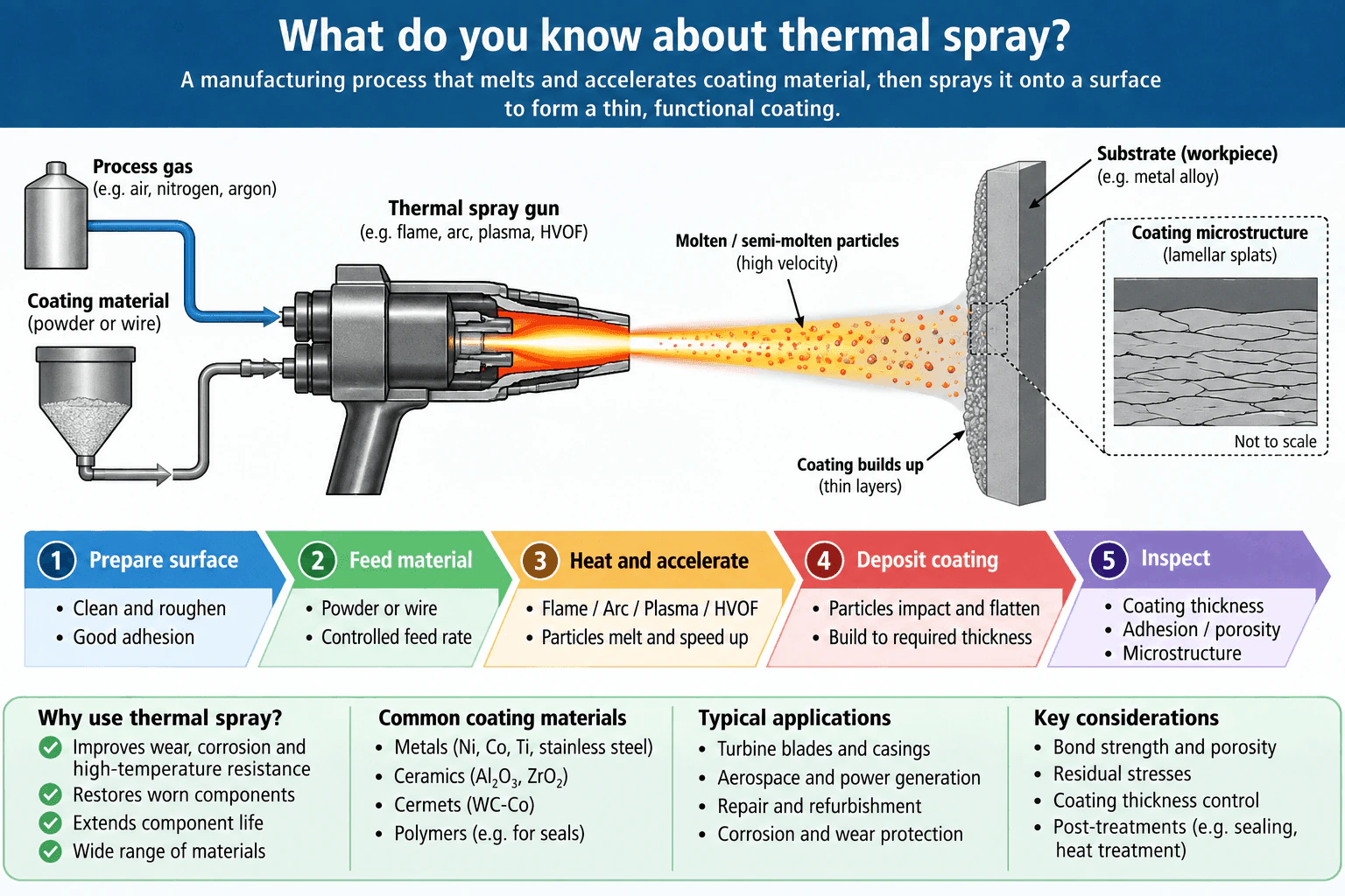
Thermal spray is a family of surface-engineering processes used to apply a functional coating to a component. The basic manufacturing flow is: prepare the surface, feed the coating material, heat or soften and accelerate it, deposit the particles onto the substrate, and inspect the finished coating.

The coating material is commonly supplied as powder or wire. Depending on the selected process, the spray equipment may use combustion, an electric arc, or a plasma as the main energy source. Process gases can include air, nitrogen, argon, oxygen, or fuel gases depending on the process, so I would not assume that one gas arrangement applies to every thermal-spray method.

Common process families include flame spray, electric arc spray, plasma spray, and HVOF. They differ in feedstock form, energy source, particle temperature, particle velocity, deposition characteristics, equipment, and cost.

During spraying, molten or semi-molten particles are accelerated toward the prepared workpiece. When they strike the substrate, they deform into flattened particles commonly called splats, cool and solidify, and progressively build a coating. Repeated splat deposition produces the characteristic layered or lamellar coating microstructure shown in the manufacturing concept.

Surface preparation is critical. The component is normally cleaned and, where required by the selected coating system, roughened to provide a suitable surface for bonding. Inadequate preparation can cause contamination, poor bond strength, local defects, or coating delamination.

Common coating materials include metals and alloys such as nickel-, cobalt-, titanium-, iron-, and stainless-steel-based materials; ceramics such as alumina and zirconia; cermets such as WC-Co; and polymers for suitable processes and applications. The coating material should be selected from the required function rather than simply choosing the hardest or highest-temperature material.

Typical reasons for using thermal spray include improving resistance to wear, corrosion, erosion, and elevated-temperature environments; providing thermal protection; restoring worn dimensions; and extending component service life. Typical applications include turbine blades and casings, aerospace and power-generation hardware, shafts and other rotating components, and repair or refurbishment of high-value parts.

The production variables I would control include coating-material feed rate, particle heating and acceleration, spray distance, spray angle, gun traverse conditions, substrate preparation, process-gas or energy settings appropriate to the selected process, and coating build-up. Depending on the engineering requirement, final inspection can include coating thickness, adhesion or bond strength, porosity, surface condition, and microstructure.

I would also consider residual stress, masking, fixturing, spray-gun access, line-of-sight limitations, deposition efficiency, overspray or scrap, cycle time, and any required post-treatment such as sealing, heat treatment, machining, grinding, or polishing.

For process selection, I would start with the substrate material, coating function, geometry, required thickness, required surface finish, production volume, inspection requirements, and cost. I would then compare the available thermal-spray processes against those requirements and qualify the chosen process using measured coating characteristics rather than assuming that a visually acceptable coating is sufficient.

Useful Questions to Ask the Interviewer
  • What is the main purpose of the coating: wear resistance, corrosion protection, thermal protection, dimensional restoration, or another function?
  • What are the substrate material and component geometry?
  • What coating material or coating-performance requirements are specified?
  • What coating thickness, adhesion, porosity, surface finish, and microstructure are required?
  • Is the component a prototype, a repair, or a repeat-production part?
  • What inspection methods and acceptance criteria are used for the critical coating characteristics?
  • Are sealing, machining, grinding, polishing, or heat treatment required after spraying?
What do you know about thermal spray? diagram
How to Explain It in an Interview

I would explain thermal spray as a five-step manufacturing sequence. First, clean and prepare the component surface. Second, feed powder or wire into the selected thermal-spray equipment at a controlled rate. Third, use the appropriate process energy source to heat or soften the feedstock and accelerate the particles. Fourth, the particles impact the substrate, flatten into splats, solidify, and build the coating to the required thickness. Fifth, inspect critical characteristics such as coating thickness, adhesion or bond strength, porosity, and microstructure.

I would then explain that flame spray, electric arc spray, plasma spray, and HVOF are different members of the same process family rather than interchangeable equipment configurations. Their energy sources, gas arrangements, feedstocks, particle temperatures, and particle velocities differ, so the correct choice depends on the coating material, substrate, geometry, required properties, production rate, and cost.

For production readiness, I would define the surface-preparation method, masking, fixture strategy, spray access, process settings, coating build-up method, inspection plan, and any post-processing. I would control the characteristics that are critical to function and use process-capability or statistical-process-control methods only when the measurement system is suitable and the manufacturing process is stable.

The main limitations are sensitivity to surface preparation and process control, possible porosity or oxide content depending on the material and process, residual stresses, line-of-sight constraints on complex geometry, overspray, and the possible need for sealing or mechanical finishing. My final process choice would therefore be based on demonstrated coating performance and manufacturing capability, not on the process name alone.

Technical Approach
  1. Define the required coating function, substrate material, component geometry, operating environment, coating thickness, surface finish, and acceptance criteria.
  2. Select a compatible coating material based on the required wear, corrosion, erosion, thermal, restoration, or other functional requirement.
  3. Compare suitable thermal-spray process families such as flame spray, electric arc spray, plasma spray, and HVOF against feedstock compatibility, coating quality, deposition rate, geometry, access, production volume, and cost.
  4. Define cleaning, surface roughening where required, masking, fixtures, and spray-gun access.
  5. Establish controlled process variables such as feed rate, process-gas or energy settings appropriate to the selected method, spray distance, spray angle, traverse conditions, and coating build-up.
  6. Deposit the coating in controlled passes until the required thickness is reached.
  7. Apply required post-processing such as sealing, heat treatment, machining, grinding, or polishing.
  8. Inspect critical characteristics such as coating thickness, adhesion or bond strength, porosity, microstructure, and final surface condition using suitable methods.
  9. Confirm process stability and repeatability before relying on the process for production.
Practical Insights

The main manufacturing tradeoff is between coating performance, process capability, production rate, and cost. Different thermal-spray processes produce different combinations of particle temperature and velocity, which affect coating structure and properties. Tighter requirements for porosity, adhesion, thickness, or surface finish can require tighter control of surface preparation, spray parameters, inspection, and finishing. Complex component geometry can increase masking, fixture, robot-path, line-of-sight, and inspection difficulty. Production decisions should also consider deposition efficiency, overspray or scrap, cycle time, consumables, equipment cost, and post-processing.

Why Interviewers Ask This

Interviewers are checking whether I understand thermal spray as a surface-engineering and manufacturing process: how the coating material is prepared and deposited, why substrate preparation matters, how major thermal-spray process families differ, what coating materials and applications are typical, and which production and inspection controls determine coating quality.

Common interview mistakes

Common mistakes are describing thermal spray as one single process; assuming flame spray, arc spray, plasma spray, and HVOF use the same gas or energy arrangement; ignoring cleaning and surface preparation; treating the coating as fully equivalent to a dense bulk material rather than a deposited lamellar structure; choosing a process without considering feedstock, substrate, geometry, access, thickness, adhesion, porosity, surface finish, and production volume; assuming more heat or particle velocity is always better; overlooking masking, fixtures, overspray, cycle time, inspection, and post-processing; and accepting a coating from appearance alone without measuring the critical characteristics.

Interview tip

Answer with the same end-to-end flow as the manufacturing diagram: prepare the surface, feed powder or wire, heat or soften and accelerate the material, deposit particles that flatten into splats and build a lamellar coating, then inspect the result. Mention flame spray, electric arc spray, plasma spray, and HVOF as different process families, and connect process selection to coating function, substrate, material, thickness, adhesion, porosity, geometry, inspection, production rate, and cost.

Interviewer may ask next
How would you validate that a thermal-spray process is producing an acceptable coating?

I would first define the critical coating characteristics from the engineering requirement rather than relying on appearance alone. Depending on the application, these can include coating thickness, adhesion or bond strength, porosity, microstructure, surface condition, and dimensional requirements. I would verify that substrate preparation and spray parameters are controlled, use suitable calibrated inspection methods, and examine representative samples when destructive evaluation is required. For production, I would place the critical characteristics in the control plan and use process-capability or statistical-process-control methods only when the measurement system is suitable and the process is stable.

How would your process choice change if very low porosity and strong coating adhesion became the main requirements?

I would re-evaluate the available thermal-spray processes rather than simply increasing the settings on the current process. I would compare process families that can provide the required particle velocity, thermal input, and coating quality for the selected feedstock and substrate. HVOF is commonly considered for suitable materials when dense, strongly bonded coatings are important, but the final choice would still depend on coating composition, substrate temperature limits, component geometry, required thickness, surface finish, production rate, equipment capability, inspection evidence, and cost. I would qualify the selected process using measured porosity, adhesion, thickness, and microstructure against the actual acceptance criteria.

9. What do you know about TIG welding?NEWManufacturingEasyRolls Royce

Short Interview Answer (30-60 seconds)

TIG welding, also called Gas Tungsten Arc Welding or GTAW, uses an electric arc between a non-consumable tungsten electrode and the workpiece. An inert shielding gas, typically argon, protects the electrode, arc, and molten weld pool from the atmosphere. Filler metal can be added separately when required. TIG gives excellent control and produces clean, precise, high-quality welds, making it useful for thin sections, stainless steel, aluminum, high-alloy parts, tubing, and critical components. Its main tradeoffs are slower welding speed, lower deposition rate, and greater operator skill compared with processes such as MIG/MAG.

Detailed Explanation

TIG welding is a fusion-welding process in which an electric arc forms between a non-consumable tungsten electrode and the workpiece. The arc provides the heat needed to melt the base material and create a weld pool. The tungsten electrode normally does not provide filler metal. If additional metal is required, a separate filler rod is fed into the weld pool.

An inert shielding gas, typically argon, flows through the TIG torch and ceramic cup around the tungsten electrode. Its purpose is to protect the hot electrode, electric arc, molten weld pool, and newly solidified weld from atmospheric contamination.

A typical TIG setup includes an AC/DC constant-current power source, shielding-gas cylinder and pressure regulator, TIG torch and torch lead, ceramic cup, non-consumable tungsten electrode, work lead and clamp, and an optional filler rod. At the joint, the electric arc creates the weld pool, and the molten metal then solidifies behind the torch to form the weld bead.

The basic process can be explained in five steps. First, prepare and clean the joint surfaces by removing oil, oxide, dirt, and other contamination. Second, set up the machine by selecting the appropriate AC or DC mode, current, tungsten, and shielding-gas flow. Third, establish the arc, maintain a controlled arc length and weld pool, and add filler rod when required. Fourth, finish the weld by stopping filler addition and maintaining shielding-gas flow briefly during post-flow so the hot tungsten and weld region remain protected. Fifth, inspect the finished weld using the acceptance method appropriate to the component, such as visual inspection and, when specified, nondestructive testing.

Current type depends on the material and welding procedure. AC is commonly used for aluminum because it can provide oxide-cleaning action while also producing the required welding heat. DC, commonly DC electrode negative for many applications, is widely used for steels. The exact current, gas flow, tungsten, filler, and other settings should be selected from the material, joint, thickness, equipment, and approved welding procedure rather than from a universal value.

The main advantages of TIG are excellent weld quality and appearance, high control and precision, suitability for thin sections and critical parts, and a clean process that normally does not require flux. These characteristics make TIG useful for aerospace components, stainless-steel and high-alloy parts, thin sheet, tubing, and other critical or high-integrity welds.

The main limitation is productivity. TIG is generally slower than MIG/MAG, has a lower filler-metal deposition rate, and requires greater operator skill. Because of this, it can be less economical for high-volume production. Clean surfaces, stable shielding-gas coverage, correct arc length, suitable current, and consistent technique are also important because poor control can lead to contamination, oxidation, inconsistent fusion, excessive heat input, or poor bead quality.

From a manufacturing-engineering perspective, I would choose TIG when its precision and weld-quality advantages justify the cycle time and skill requirements. I would consider the material, section thickness, joint geometry, required weld integrity, distortion sensitivity, torch and filler access, inspection access, production volume, fixture requirements, scrap or rework risk, and total manufacturing cost. For thin, precise, low-volume, or critical welds, TIG can be a strong process choice. For high-volume fabrication where deposition rate and cycle time dominate, I would compare it with a faster welding process that can still meet the required quality.

Useful Questions to Ask the Interviewer
  • What material and thickness are being welded?
  • Is the weld structural, cosmetic, fatigue-critical, pressure-containing, or otherwise quality-critical?
  • What joint geometry and access are available for the torch and filler rod?
  • What production volume and cycle-time target apply?
  • Is manual, mechanized, or automated TIG being considered?
  • What inspection and acceptance requirements apply to the weld?
  • Is distortion or heat input a major concern?
  • Is there an approved welding procedure controlling current type, filler metal, shielding gas, or inspection?
What do you know about TIG welding? diagram
How to Explain It in an Interview

I would start with the operating principle: TIG uses a non-consumable tungsten electrode to create an electric arc, inert shielding gas such as argon to protect the weld area, and a separate filler rod only when additional metal is required. I would then explain the process in the same practical order used on the shop floor: prepare the surfaces, set up the AC/DC power source and gas, weld while controlling the arc and weld pool, maintain post-flow when finishing, and inspect the solidified weld. I would finish by explaining the manufacturing tradeoff: TIG gives excellent control, appearance, and weld quality, especially on thin or critical components, but it is generally slower, has a lower deposition rate, and requires more skill than MIG/MAG. The final process choice therefore depends on material, geometry, required quality, accessibility, production volume, inspection requirements, and cost.

Technical Approach
  1. Identify the base material, section thickness, joint geometry, weld function, accessibility, required quality, and production volume.
  2. Decide whether TIG is appropriate based on the need for precision, heat control, weld appearance, and integrity versus deposition-rate and cycle-time requirements.
  3. Select the required setup: AC or DC constant-current power source, TIG torch, ceramic cup, non-consumable tungsten electrode, inert shielding gas such as argon, work lead and clamp, and filler rod when required.
  4. Prepare and clean the joint surfaces to remove oil, oxide, dirt, and other contamination.
  5. Set current, gas flow, tungsten, filler, and related parameters using the material requirements, equipment guidance, and applicable welding procedure.
  6. Establish the electric arc and maintain controlled arc length, torch position, travel speed, shielding coverage, and weld-pool size.
  7. Add the separate filler rod when required by the joint or weld specification.
  8. Finish the weld by stopping filler addition and maintaining appropriate shielding-gas post-flow over the hot tungsten and weld region.
  9. Inspect the solidified weld using the required acceptance method, beginning with visual inspection and adding nondestructive testing when specified.
  10. For production, monitor critical characteristics, cycle time, rework, scrap, fixture performance, and inspection access so the process remains capable and economical.
Practical Insights

TIG trades production speed for control. It can produce precise, clean, high-quality welds with excellent control of the arc, weld pool, heat input, and separate filler addition. The disadvantages are slower welding speed, lower deposition rate, higher operator-skill requirements, and greater sensitivity to cleanliness and shielding-gas control. Fixtures can improve repeatability and distortion control but add tooling cost and must still allow torch, filler, and inspection access. For production, the process should be judged not only by whether a good weld can be produced once, but also by whether the required quality can be produced consistently at an acceptable cycle time, scrap rate, and total cost.

Why Interviewers Ask This

Interviewers ask this to check whether you understand the TIG welding process, its equipment and operating principles, where it is useful, and the production tradeoffs involved. A strong answer shows that you can connect weld quality and material requirements with shielding gas, electrode choice, current type, cleanliness, operator skill, inspection, cycle time, and production volume.

Common interview mistakes

Common mistakes include describing the tungsten electrode as the filler metal; forgetting that filler rod is separate and may be optional; confusing inert shielding gas with an active shielding gas; assuming one current type is correct for every material; welding over oil, oxide, moisture, or other contamination; using excessive arc length; allowing poor shielding-gas coverage; stopping shielding gas immediately instead of allowing appropriate post-flow; choosing TIG for high-volume production without considering its slower cycle time and lower deposition rate; ignoring torch, filler, fixture, and inspection access; and judging weld quality from appearance alone without applying the required acceptance criteria.

Interview tip

Start with the operating principle: non-consumable tungsten electrode, electric arc, inert shielding gas, and optional separate filler rod. Then explain the process from preparation through setup, welding, post-flow, and inspection. Finish with the process-selection judgment: TIG gives excellent control and high-quality welds, but compared with MIG/MAG it is generally slower, has a lower deposition rate, and requires more skill. That combination of process knowledge and manufacturing tradeoff is stronger than simply listing applications.

Interviewer may ask next
How would you verify that a TIG welding process is ready for production rather than relying on one good-looking weld?

I would confirm that the material, joint design, tungsten, filler, shielding gas, current mode, equipment, and welding procedure are appropriate for the application. I would then produce representative welds under controlled conditions and inspect them against the required acceptance criteria. Visual inspection can identify surface conditions, while additional nondestructive or destructive testing would depend on the component requirements. For production, I would also verify repeatability by monitoring relevant critical characteristics, process stability, distortion, rework, scrap, and cycle time. Fixtures and inspection access should be validated as part of the manufacturing setup. A visually attractive weld alone is not enough evidence of consistent production capability.

If production volume increased significantly, would you still choose TIG welding?

Not automatically. I would reassess the process because manual TIG is relatively slow and has a lower deposition rate than processes such as MIG/MAG. If the part still requires the heat control, cleanliness, precision, or weld integrity that makes TIG attractive, mechanized or automated TIG could be considered. If another welding process can meet the material, geometry, quality, distortion, and inspection requirements with a shorter cycle time and lower total cost, I would evaluate that alternative. The decision should balance weld quality with production rate, tooling, labor, scrap, inspection, and manufacturing cost.

10. What do you know about laser welding when it's aluminium to aluminium?NEWManufacturingMediumRolls Royce

Short Interview Answer (30-60 seconds)

Laser welding can be a very effective aluminium-to-aluminium joining process because the concentrated heat source allows fast welding, a narrow fusion zone, and relatively low distortion. Aluminium is challenging because it is highly reflective to near-infrared laser light, conducts heat rapidly, has a tenacious aluminium-oxide surface layer, and is susceptible to hydrogen-related porosity. I would start with clean, dry surfaces and tight, repeatable fit-up, then control laser power, focus position, travel speed, and argon or helium shielding. For deeper, narrow welds, a stable keyhole process may be used. I would then inspect for porosity, lack of fusion, cracks, and surface defects and control fixtures, parameters, cleanliness, cycle time, and scrap in production.

Detailed Explanation

Laser welding aluminium to aluminium is mainly about controlling energy absorption, cleanliness, fit-up, shielding, and process stability. A focused laser melts a small region of the joint. At sufficiently high power density, vapour pressure can create a keyhole, producing a relatively deep and narrow weld. Because the energy is concentrated and travel speeds can be high, laser welding can provide comparatively low overall heat input and low distortion.

Aluminium needs special attention for four reasons. First, it has high reflectivity to near-infrared laser radiation, particularly before melting, so stable coupling of laser energy into the material is important. Second, its high thermal conductivity removes heat rapidly from the weld region. Third, aluminium naturally develops a tenacious Al₂O₃ oxide layer whose melting temperature is much higher than that of the aluminium substrate, so joint preparation is important. Fourth, hydrogen-related porosity can occur because hydrogen is much more soluble in molten aluminium than in solid aluminium; moisture and contamination on the material or oxide surface can therefore contribute to pores during solidification.

The manufacturing sequence is Prepare -> Set Parameters -> Weld -> Inspect -> Control in Production. I would begin with clean, dry joint surfaces, removing oil, dirt, moisture, and surface oxide as required by the qualified preparation procedure. I would fixture and clamp the components so alignment and joint gap stay low and repeatable. I would also confirm that the particular aluminium alloys, tempers, thicknesses, and joint design are suitable because aluminium alloy families do not all have identical weldability or cracking behaviour.

Next, I would establish a qualified welding window for laser power, focus position, travel speed, beam condition, and shielding. Fibre lasers operating in the near-infrared are commonly used for aluminium, but the actual equipment and wavelength should be treated as process inputs rather than assumed. Argon or helium can be used as shielding gases, with the nozzle position and flow selected to protect the molten region without unnecessarily disturbing the process.

For a deep, narrow weld, keyhole mode may be appropriate. The laser creates the molten pool and keyhole at the beam location while the solidified weld forms behind it as the process moves along the joint. The important point is process stability: too little absorbed energy can lead to incomplete penetration or lack of fusion, while excessive or unstable energy input can cause excessive penetration, spatter, an unstable keyhole, or other weld defects. The correct process window depends on alloy, thickness, joint type, fit-up, beam characteristics, focus, and required weld geometry.

Inspection must match the defect risk and the application. Visual inspection can identify surface condition, visible cracking, excessive spatter, or other external defects. Where internal quality is important, an appropriate non-destructive examination method such as radiography or ultrasonic inspection may be used if suitable for the geometry and expected defect type. Mechanical testing may also be required during qualification to demonstrate that the joint meets the required performance.

For production, repeatability is as important as making one good prototype weld. Fixtures and automation can keep the joint position and gap consistent. Clean, dry conditions should be maintained. Key variables such as power, travel speed, focus condition, beam alignment, and shielding should be controlled or monitored. A control plan and statistical process control can be applied to critical characteristics after the measurement system is suitable and the process is shown to be stable. Process capability metrics such as Cp and Cpk should only be interpreted after those conditions are met. Cycle time and scrap should also be tracked because a technically acceptable weld process may still be unsuitable for production if it is too slow, unstable, or wasteful.

Useful Questions to Ask the Interviewer
  • Which aluminium alloys and tempers are being joined?
  • What is the material thickness and joint type, such as butt or lap?
  • Is the requirement full penetration, partial penetration, or a specified weld size?
  • What joint-gap and alignment variation must the fixture accommodate?
  • What laser source, wavelength, beam delivery system, and power range are available?
  • What shielding gas and gas-delivery arrangement are available?
  • Which defects and acceptance criteria are critical, such as porosity, cracks, lack of fusion, penetration, distortion, or surface condition?
  • What inspection method is available, and is the joint accessible for that inspection?
  • Is this a prototype process or a production process where automation, cycle time, process capability, and scrap are major concerns?
What do you know about laser welding when it's aluminium to aluminium? diagram
How to Explain It in an Interview

I would explain it as an end-to-end manufacturing process. First, aluminium is challenging because it is reflective, conducts heat quickly, has a tenacious oxide layer, and can develop hydrogen-related porosity. Second, I would control the inputs that directly affect the weld: surface cleanliness, joint gap and alignment, laser power, focus position, travel speed, and shielding gas. If the required weld is deep and narrow, I would establish a stable keyhole process rather than simply increasing power. Third, I would validate the weld using visual, non-destructive, and mechanical inspection methods appropriate to the application. Finally, I would move the qualified process into production using fixtures, automation where appropriate, parameter monitoring, cleanliness controls, a control plan, and statistical process control. The main point is that reliable aluminium laser welding comes from a controlled and repeatable process window, not from laser power alone.

Technical Approach
  1. Define the aluminium alloys, tempers, thicknesses, joint geometry, required penetration or weld size, production volume, and acceptance criteria.
  2. Confirm that laser welding is suitable for the material combination, geometry, tolerance, cycle-time target, cost, and inspection access.
  3. Prepare clean, dry joint surfaces and remove oil, dirt, moisture, and surface oxide as required by the qualified preparation procedure.
  4. Fixture and clamp the parts so alignment and joint gap remain low and repeatable.
  5. Establish a qualified process window for laser power, focus position, travel speed, beam condition, and argon or helium shielding.
  6. Produce trial welds and assess keyhole stability where keyhole mode is used, along with penetration, fusion, surface quality, distortion, and process consistency.
  7. Inspect for relevant defects such as porosity, lack of fusion, cracks, excessive spatter, and unacceptable penetration using methods appropriate to the application.
  8. Where required, verify mechanical properties during process qualification.
  9. Transfer the approved settings into production with repeatable fixtures, automation where justified, parameter monitoring, cleanliness controls, and a documented control plan.
  10. After confirming measurement-system suitability and process stability, apply statistical process control and appropriate capability measures such as Cp or Cpk to critical measurable characteristics.
  11. Continue monitoring cycle time, scrap, shielding performance, beam or optic condition, and process drift.
Practical Insights

The main manufacturing tradeoff is providing enough concentrated energy for consistent fusion while avoiding an unstable or excessive weld. Higher laser power or lower travel speed generally increases energy delivered to the joint, but simply adding energy is not always better because it can increase penetration, spatter, keyhole instability, or thermal effects. Faster travel can reduce cycle time and overall heat input, but only if adequate fusion and penetration are maintained. Tight fit-up and careful cleaning improve repeatability but add tooling and preparation effort. More inspection increases confidence but also adds manufacturing cost and cycle time. The preferred production solution is therefore a stable process window that meets weld-quality requirements with practical fixtures, suitable inspection access, acceptable scrap, and acceptable cycle time.

Why Interviewers Ask This

Interviewers are testing whether the candidate understands the aluminium-specific challenges of laser welding and can connect material behaviour to preparation, joint fit-up, laser settings, shielding, defect prevention, inspection, and production control rather than describing laser welding only in general terms.

Common interview mistakes

Common mistakes are assuming all aluminium alloys behave the same; welding through oil, dirt, moisture, or poorly controlled oxide; allowing inconsistent joint gap or alignment; selecting laser power without considering travel speed, focus, alloy, thickness, and joint design; assuming more power automatically produces a better weld; using poorly positioned or unsuitable shielding; ignoring porosity, lack of fusion, cracking, and penetration risks; relying only on surface appearance when internal integrity matters; quoting Cp or Cpk before establishing a suitable measurement system and stable process; and transferring a successful prototype weld into production without controlling fixtures, cleanliness, monitoring, cycle time, and scrap.

Interview tip

Structure the answer around aluminium's material challenges and then walk through Prepare -> Set Parameters -> Weld -> Inspect -> Control in Production. Mention reflectivity, thermal conductivity, the Al₂O₃ oxide layer, hydrogen-related porosity, tight fit-up, laser power, focus, travel speed, shielding, keyhole stability, inspection, fixtures, automation, and statistical process control. Avoid giving universal numeric settings because the correct process window depends on the exact alloy, thickness, joint geometry, equipment, and acceptance criteria.

Interviewer may ask next
How would you validate that an aluminium laser-welding process is ready for production?

I would first define the critical weld requirements and acceptance criteria, then run controlled trials across the intended process window. I would verify joint fit-up, surface preparation, laser power, focus position, travel speed, shielding, penetration, fusion, porosity, cracking, surface condition, and distortion using inspection methods appropriate to the application. Where required, I would perform mechanical testing during qualification. After selecting the process window, I would confirm that the fixture and measurement system are repeatable, establish a control plan for critical characteristics, and demonstrate process stability before interpreting Cp or Cpk. I would also track cycle time and scrap so the process is both technically acceptable and manufacturable at the required volume.

What would change if the production joint had a larger or more variable gap?

A larger or variable gap makes a tightly focused laser process harder to control because the beam may not consistently bridge the joint or produce the required fusion geometry. I would first reduce the variation through part tolerances, joint design, and better fixturing if possible. If the gap cannot be reduced, I would re-evaluate the joint configuration and qualified welding process, including whether beam positioning, process parameters, filler-assisted laser welding, or another joining process would be more suitable. Any change would need to be revalidated for penetration, fusion, defects, distortion, cycle time, scrap, and production capability.

Disclaimer: This interview guide is for educational and informational purposes only. It is designed to help readers prepare, but it does not guarantee any interview result, hiring decision, offer, or outcome. Interview questions, hiring criteria, and preferred answers can vary by employer, interviewer, industry, location, and time. All answers, examples, and explanations in this guide are suggested examples for interview preparation, not definitive answers or instructions for professional practice. They are based on research and judgment, are provided without warranties of any kind, and should be adapted to the question, role, and applicable laws and professional requirements. Diagrams are simplified illustrations intended to highlight the main concepts and their relationships; actual situations, systems, and practices may be more complex. Alternative approaches may be equally valid or better suited to a particular question, context, or interviewer. To the fullest extent permitted by applicable law, the contributors and publisher are not liable for decisions made, actions taken, or losses incurred based on this guide.

State Laws and Professional Responsibilities: Laws and requirements governing an occupation vary by state and jurisdiction. You are responsible for checking the current laws, licensing requirements, and scope-of-practice rules that apply to your location and role, and for ensuring that your answers and actions comply with them. Adapt examples in this guide to those requirements. This guide is not legal advice.

Company Notice: This guide is an independent educational resource and is not affiliated with, endorsed by, sponsored by, or approved by the company named in this guide. Company names identify reported interview experiences or the employer context of clearly labeled original practice exercises. Interview practices can change without notice, and inclusion of company-specific content does not mean these questions are official, complete, or guaranteed to be asked. To the fullest extent permitted by law, the author, contributors, and publisher are not responsible for outcomes related to use of this material.

Content Accuracy and Verification: To the fullest extent permitted by applicable law, we do not represent or warrant that interview guides, questions, answers, examples, or diagrams are accurate, complete, current, error-free, or suitable for any particular purpose. You are responsible for independently reviewing and verifying the information before relying on it.