10 Tesla Mechanical Engineer Interview Questions & Answers

tesla icon

Questions with Detailed ExplanationsWith Detailed Explanations

(Last Updated: September 13, 2026)

1. What are the degrees of freedom of a rectangular sheet with one face fixed to a table?Engineering MechanicsEasyTesla

Short Interview Answer (30-60 seconds)

A free rigid body in 3D has six degrees of freedom: three translations and three rotations. If one entire face of the rectangular sheet is perfectly fixed to a rigid table, the constraint prevents translation in x, y, and z and rotation about x, y, and z. So the sheet has 0 rigid-body degrees of freedom. Elastic deformation modes are separate and are not part of this rigid-body DOF count.

Detailed Explanation

The key is to state what kind of degrees of freedom are being counted. For this question, treat the rectangular sheet as a rigid body.

A free rigid body in three-dimensional space has six independent rigid-body motions:

  • Translation along x: u_x
  • Translation along y: u_y
  • Translation along z: u_z
  • Rotation about x: θ_x
  • Rotation about y: θ_y
  • Rotation about z: θ_z

The boundary condition says one entire face is fixed to a rigid table. Interpreting "fixed" as no slip, no separation, and no rigid-body rotation, the constraints are:

u_x = u_y = u_z = 0

θ_x = θ_y = θ_z = 0

All six rigid-body motions are therefore restrained, leaving 0 rigid-body degrees of freedom.

It is important not to confuse this result with elastic deformation. A real deformable plate can still have internal deformation fields or vibration modes depending on its material, geometry, loading, and structural model. Those deformation modes are outside the rigid-body DOF count used here.

Useful Questions to Ask the Interviewer
  • Should I treat the sheet as a rigid body or as a deformable plate? For the basic DOF interpretation, I would treat it as a rigid body.
  • Does "fixed" mean the entire face is perfectly attached to a rigid table with no slip or separation? Under that assumption, all six rigid-body motions are removed.
  • Are you asking for rigid-body DOF or finite-element nodal DOF? Those are different concepts and can give different counts.
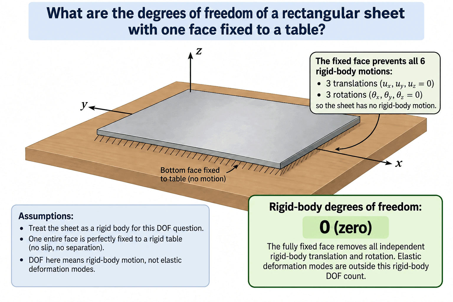
What are the degrees of freedom of a rectangular sheet with one face fixed to a table? diagram
How to Explain It in an Interview

Start with the unconstrained case: a rigid body in 3D has six independent motions, consisting of three translations and three rotations. Then apply the boundary condition. Because the entire face is fixed to the table, none of those translations or rotations can occur as rigid-body motion. The result is therefore 0 rigid-body DOF. I would finish by noting that an elastic sheet may still have internal deformation modes, but those are outside this rigid-body DOF count.

Technical Approach

1. Define the sheet as the body of interest and choose x, y, and z coordinates. 2. Start with the six rigid-body degrees of freedom of a free body in 3D: u_x, u_y, u_z, θ_x, θ_y, and θ_z. 3. Apply the fixed-face boundary condition: no translation, no rotation, no slip, and no separation relative to the rigid table. 4. Set u_x = u_y = u_z = 0 and θ_x = θ_y = θ_z = 0. 5. Count the remaining independent rigid-body motions. None remain, so the result is 0 rigid-body DOF. 6. State separately that elastic deformation modes are not included in this rigid-body count.

Practical Insights

There is no meaningful computational complexity for this conceptual mechanics question. The important modeling issue is the definition of DOF. Under a rigid-body model, the fixed face removes all six global rigid-body motions, leaving 0 rigid-body DOF. Under a deformable structural or finite-element model, internal deformation degrees of freedom can still exist away from the constrained interface, so the model type must be stated clearly.

Why Interviewers Ask This

This question tests whether the candidate understands rigid-body degrees of freedom and how a fixed boundary condition removes translational and rotational motion. It also checks whether the candidate can distinguish rigid-body motion from elastic deformation rather than treating every possible deformation as a rigid-body degree of freedom.

Common interview mistakes

Common mistakes include saying the sheet has three DOF because it can supposedly bend or rotate even though the entire face is fixed, counting only translational constraints and forgetting rotations, treating a fixed face like a pin or simple support, or saying that 0 rigid-body DOF means an elastic structure can never deform internally. Another mistake is failing to state whether the question refers to rigid-body DOF or finite-element nodal DOF.

Interview tip

State the assumption first: "Treating the sheet as a rigid body and the entire face as perfectly fixed to a rigid table." Then count the six free rigid-body motions and explicitly eliminate all six. Finish with "0 rigid-body DOF," and briefly distinguish that result from elastic deformation modes.
Interviewer may ask next
What assumption is most important when concluding that the sheet has 0 degrees of freedom?

The key assumption is that the question is asking for rigid-body degrees of freedom and that the entire face is perfectly fixed to a rigid table. That means no translation in x, y, or z and no rotation about x, y, or z. If the support allowed slip, separation, or rotation, one or more rigid-body degrees of freedom could remain.

How would the answer change if the sheet were modeled as an elastic plate instead of only as a rigid body?

The fixed face would still eliminate the sheet's global rigid-body motion, so there would be 0 unconstrained rigid-body DOF. However, an elastic plate model can still have internal deformation degrees of freedom at unconstrained locations, allowing strain, bending, and vibration under load. The exact number of those deformation DOFs depends on the structural formulation and discretization.

2. What is the difference between power and energy?Engineering MechanicsEasyTesla

Question Details

How do you transfer torque to energy?

Short Interview Answer (30-60 seconds)

Energy tells you how much work can be done or has been transferred, while power tells you how quickly that energy is transferred. Energy is measured in joules, and power is measured in watts, or joules per second. In rotation, torque transfers energy when it acts through an angular displacement: for constant torque, W = τθ. If the shaft rotates at angular speed ω, the instantaneous power is P = τω. So torque times angle gives energy, while torque times angular speed gives power.

Detailed Explanation

Power and energy describe related but different physical quantities. Energy is an amount of work or transferred capacity, while power is the rate at which that energy is transferred.

For translational motion, mechanical work is force acting through a displacement. For rotational motion, the equivalent relationship uses torque and angular displacement. If a constant torque τ acts while a shaft rotates through an angle θ, the transferred work or energy is:

W = τθ

where W is work or energy in joules (J), τ is torque in newton-metres (N·m), and θ is angular displacement in radians. Because a radian is dimensionless, N·m has the same dimensions as a joule when it represents work.

Power describes how quickly that work is being done. For rotational motion:

P = τω

where P is power in watts (W), τ is torque in N·m, and ω is angular velocity in radians per second. A watt is one joule per second.

The energy transferred over a time interval is therefore the integral of power:

E = ∫P dt

For constant power, this simplifies to E = Pt.

A useful distinction is that torque alone does not specify energy. A stationary shaft can have torque applied to it but, if there is no angular displacement, no rotational mechanical work is transferred through that motion. Similarly, knowing torque without rotational speed is not enough to determine instantaneous power.

Useful Questions to Ask the Interviewer
  • Are we discussing rotational mechanical power at a shaft, or electrical or thermal power elsewhere in the system?
  • Can torque be treated as constant, or does it vary with shaft angle or time?
  • Is the angular speed constant, or do we need the instantaneous relationship P = τω?
  • Are losses such as friction, gearbox losses, or motor efficiency included, or are we considering ideal mechanical transfer only?
How to Explain It in an Interview

I would first state the distinction: energy is an amount, while power is a rate. Then I would connect that distinction to rotational mechanics. If torque is constant and the shaft rotates through an angular displacement θ, the energy transferred is W = τθ. If the shaft is rotating at angular velocity ω, the instantaneous power is P = τω. I would check the units: N·m multiplied by radians gives joules when the quantity represents work, while N·m multiplied by radians per second gives watts. If torque or speed varies, I would use the instantaneous relationship P = τω and integrate power over time to obtain total energy. This makes clear that torque must act through an angular displacement to transfer rotational mechanical energy.

Technical Approach
  1. Define the quantity being requested: energy is an amount of work or energy transferred, while power is the rate of energy transfer.
  2. Identify whether the motion is translational or rotational.
  3. For rotational motion, define torque τ, angular displacement θ, and angular velocity ω.
  4. Use W = ∫τ dθ for rotational work; if torque is constant, use W = τθ.
  5. Use P = τω for instantaneous rotational power.
  6. If total energy over time is required, use E = ∫P dt.
  7. Retain units throughout the calculation and verify that energy is in joules and power is in watts.
  8. State assumptions such as constant torque or constant speed and account for losses separately if the real system requires them.
Practical Insights

The main engineering tradeoff is between torque, speed, power, and operating time. The same amount of energy can be delivered slowly at low power or quickly at high power. In a rotating machine, increasing torque at a fixed speed, or increasing speed at a fixed torque, increases mechanical power. Real components may then face higher loads, heating, friction losses, vibration, or speed limits. Real systems also have efficiencies below 100%, so input energy and useful output energy are not generally identical.

Why Interviewers Ask This

The interviewer is checking whether the candidate can distinguish an amount of mechanical work from the rate at which that work is performed, maintain correct units, and connect torque, angular displacement, rotational speed, power, and energy using first-principles mechanics.

Common interview mistakes

Common mistakes are treating power and energy as interchangeable, saying torque alone is energy, using P = τω without defining angular speed, forgetting that rotational work requires angular displacement, mixing revolutions per minute directly with radians per second without conversion, and assuming that because torque and work can both be expressed dimensionally as N·m they are the same physical quantity.

Interview tip

Give the distinction first: energy is an amount and power is a rate. Then use the rotational pair W = τθ and P = τω. Define every symbol and finish with a unit check: joules for energy and watts for power.

Interviewer may ask next
What changes if the torque is not constant as the shaft rotates?

Use the general rotational-work relationship W = ∫τ dθ rather than W = τθ. The torque must be integrated over angular displacement. For power, the instantaneous relationship is still P = τω using the torque and angular velocity at that instant. Integrating that power over time gives the same total transferred energy when the variables are described consistently.

If two motors deliver the same torque but one rotates twice as fast, how do their power and energy compare?

Using P = τω, the motor rotating twice as fast produces twice the mechanical power if both deliver the same torque. Energy depends on how long each motor operates or how far each rotates. If both run for the same amount of time under those conditions, the faster motor transfers twice as much energy because E = ∫P dt. If instead both rotate through the same angular displacement at the same torque, they transfer the same mechanical work W = τθ, but the faster motor completes that transfer in less time.

3. Why is the end of a traffic light pole tapered?Engineering MechanicsMediumTesla

Short Interview Answer (30-60 seconds)

The mast arm is tapered mainly because its bending-moment demand is highest near the pole and generally decreases toward the free end. That means the arm needs a larger section near its fixed connection but can use a smaller section near the traffic signal. The taper puts material where it is most useful, reducing unnecessary weight while still carrying the signal and environmental loads. In a real design, engineers would also check stress, deflection, fatigue, vibration, connection behavior, and the applicable structural requirements.

Detailed Explanation

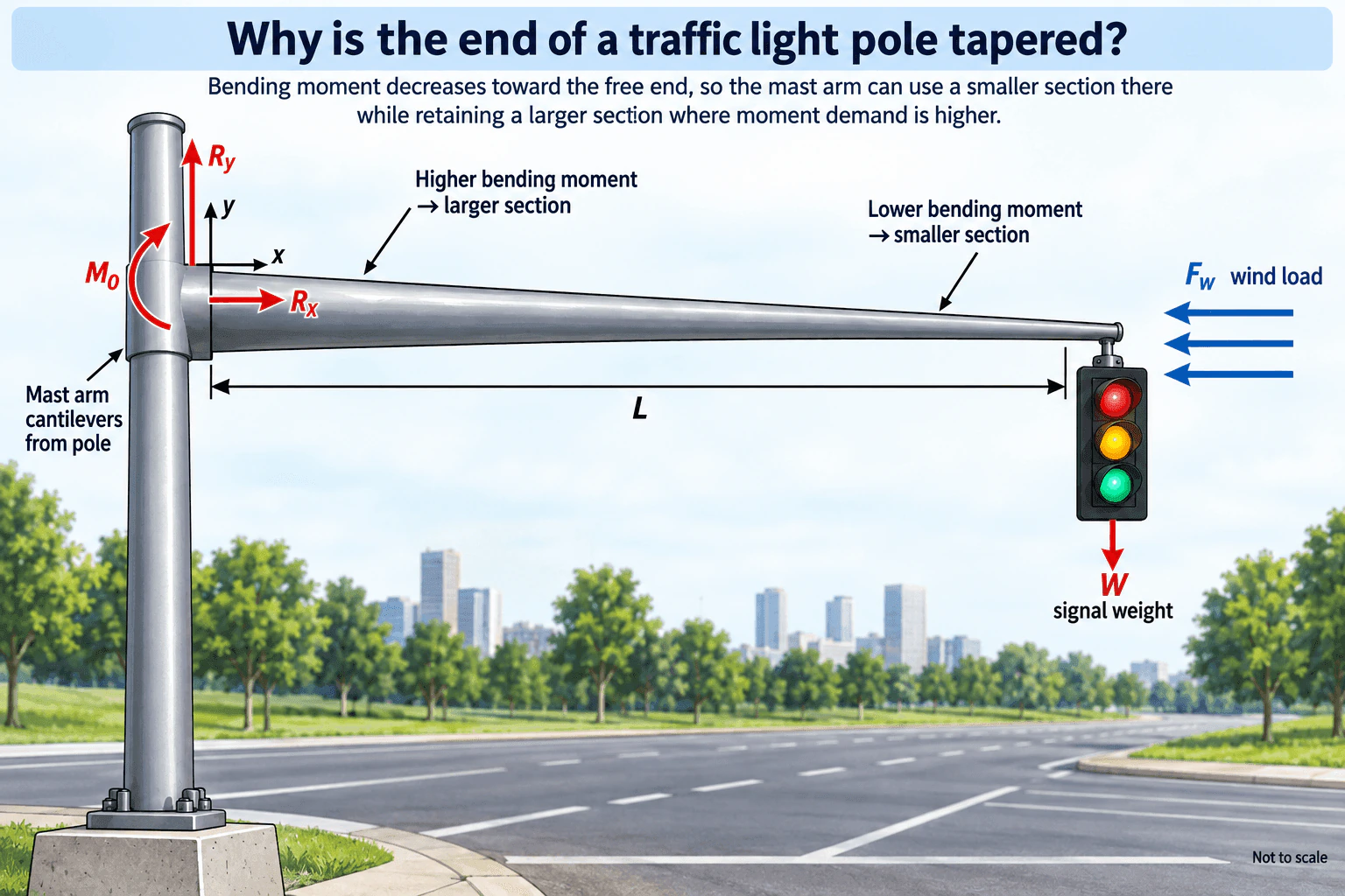
A traffic-light mast arm can be modeled conceptually as a cantilever extending from the vertical support pole. The larger end is at the fixed connection, and the arm gradually becomes smaller toward the traffic signal.

The important mechanics idea is bending moment. Suppose the signal produces a downward force W at a distance L from the mast-arm connection. For a simplified point-load model, the bending moment at the connection has magnitude approximately W L. At a section closer to the signal, the remaining lever arm is shorter, so the bending moment caused by that load is smaller. Distributed self-weight and other service loads change the exact internal-force distribution, but the same basic design principle remains: the root region generally carries greater bending demand than the tip region.

The diagram is consistent with this model. W represents the downward signal weight, F_w represents a horizontal wind load, and the fixed mast-arm connection provides reaction components R_x and R_y together with a reaction moment M_0. The x-axis runs along the mast arm, the y-axis is vertical, and L represents the arm length to the signal-load location. The arm has a larger section near the pole, where bending demand from the downward signal load is higher, and a smaller section near the free end, where that bending demand is lower.

The taper should not be described as automatically reducing bending stress everywhere. Stress depends on both the internal forces and moments and the local section geometry. Instead, the designer chooses section properties along the arm so that strength and stiffness are appropriate for the local demand. Tapering can therefore make the structure more material-efficient than keeping the largest required section over the entire length.

Wind is also an important design load. The diagram shows a horizontal wind force F_w and the corresponding horizontal support reaction R_x. Depending on the actual wind direction relative to the mast arm and signal, wind may produce axial force, bending, torsion, or a combination of these effects. Because wind can fluctuate, a real design may also require fatigue and vibration checks rather than only a static-strength calculation.

Useful Questions to Ask the Interviewer
  • Are we discussing the horizontal mast arm rather than the vertical support pole?
  • Should I explain only the first-principles statics, or also mention fatigue and wind-induced vibration?
  • Can I treat the traffic signal as a concentrated downward load for the conceptual explanation, while noting that real structures also have distributed self-weight and environmental loads?
Why is the end of a traffic light pole tapered? diagram
How to Explain It in an Interview

Start by defining the boundary condition: the mast arm behaves approximately like a cantilever fixed to the vertical pole. Then identify the major loads shown in the diagram: the signal weight W acts downward, while F_w represents a horizontal wind load. At the fixed connection, static equilibrium requires horizontal and vertical reactions, R_x and R_y, together with a reaction moment M_0.

Next, explain the bending-moment distribution from the downward signal load. For the simplest case of a point load W at the free end, the bending moment magnitude at a section is proportional to the remaining distance between that section and the load. It is therefore largest at the fixed end and approaches zero at the load location. A larger section is useful near the support because that region has the greatest bending demand. Farther toward the tip, less section is generally required, so the arm can taper.

Then state the tradeoff: using the maximum root section for the entire arm would add material and self-weight that are not equally useful everywhere. A tapered geometry allocates more material where structural demand is high and less where demand is lower. However, the final geometry cannot be chosen from bending moment alone. Engineers must verify stresses, deflection, local connection behavior, fatigue under cyclic loading, possible vibration or resonance, and all relevant load directions.

Finally, validate the reasoning. The units of bending moment are force times length, such as N·m. The limiting case also makes physical sense: as a section approaches the free-end load location, its lever arm for that point load approaches zero, so that load's bending-moment contribution approaches zero. The exact production design would still require the actual geometry, loads, material properties, environmental conditions, boundary conditions, and applicable design requirements before determining whether any particular taper is acceptable.

Technical Approach
  1. Define the free-body boundary as the horizontal mast arm and identify its fixed connection to the vertical pole.
  2. Choose coordinates, with x along the arm and y vertical.
  3. Identify the external loads shown in the diagram: downward signal weight W and horizontal wind load F_w.
  4. Apply static equilibrium to determine the required support reactions R_x, R_y, and reaction moment M_0 for the chosen load model.
  5. Determine how internal shear and bending moment vary along the mast arm; for a simplified downward end load W, the bending-moment contribution decreases as the remaining lever arm to the load decreases.
  6. Relate the local bending demand to the required section properties without confusing bending moment with stress or strength.
  7. Use a larger section near the pole and allow a smaller section toward the free end where bending demand is lower, subject to all governing load cases.
  8. Check deflection, local stresses, connection behavior, fatigue, wind-induced vibration, resonance, and relevant combined-loading effects.
  9. Validate units, equilibrium, sign convention, boundary conditions, and limiting cases.
  10. Confirm the final geometry using actual loads, dimensions, material properties, environmental conditions, and applicable engineering requirements rather than relying on the simplified conceptual model alone.
Practical Insights

The main tradeoff is structural capacity versus material and weight. A constant arm sized for the high bending demand near the pole would generally use more material than needed near the free end. Tapering can reduce that unnecessary material and the arm's own weight, but the section cannot simply be made as small as possible. It still needs adequate strength and stiffness for all governing load directions, acceptable deflection, fatigue resistance under repeated loading, suitable vibration behavior, and reliable connection details. Manufacturing and inspection constraints can also limit how aggressively the geometry is tapered.

Why Interviewers Ask This

Interviewers are testing whether the candidate can connect a visible structural feature to first-principles mechanics. A strong answer should recognize the mast arm as a cantilever, identify the external loads and support reactions, explain how bending moment changes along the arm, distinguish bending moment from stress and strength, and recognize that a real design also requires fatigue, stiffness, vibration, connection, and environmental-load checks.

Common interview mistakes

Common mistakes are saying that the taper automatically reduces bending stress without explaining the change in section properties; claiming the only purpose is aerodynamics or appearance; confusing the horizontal mast arm with the vertical support pole; ignoring the fixed-end reactions and moment; assuming bending moment is constant along the arm; treating every horizontal wind load as producing the same type of bending regardless of its direction relative to the arm; or claiming that a simple static calculation alone proves the real structure is safe without checking deflection, fatigue, vibration, connections, actual material properties, environmental loads, and applicable design requirements.

Interview tip

Lead with the cantilever model and the bending-moment distribution from the downward signal load: highest demand near the pole, lower demand toward the free end. Then connect that directly to section sizing: larger near the root, smaller near the tip. Mention the wind load and support reactions shown in the diagram, and finish by noting that a real design must also pass stiffness, fatigue, vibration, combined-loading, and connection checks.

Interviewer may ask next
How would you validate whether the chosen taper is actually adequate?

I would replace the conceptual load model with the actual geometry and loading. I would determine the governing gravity, wind, and other required load cases, verify support reactions and internal-force distributions, and evaluate stresses and deflections using the real section properties along the tapered arm. I would also check local connection stresses, fatigue from cyclic loading, and wind-induced vibration or resonance where relevant. Material properties would have to match the actual operating conditions. Finally, I would verify equilibrium, units, boundary conditions, limiting cases, and compliance with the applicable design requirements. Passing one simplified bending calculation would not by itself establish that the structure is safe.

What changes if a much heavier traffic signal is installed farther from the pole?

Both changes increase bending demand at the mast-arm root. In the simplified point-load model, the root bending moment contribution is proportional to W L, so increasing either the load W or its distance L increases the moment. The existing taper might therefore no longer provide adequate strength or stiffness. The larger load could also increase deflection and cyclic stress ranges, so fatigue and vibration behavior may change as well. I would recalculate the full load distribution and reactions, then reassess the required section properties and connection capacity before accepting the modified configuration.

4. How would you determine the diameter of a bolt in double shear with a known force?Engineering MechanicsMediumTesla

Question Details

Explain the method for determining the bolt diameter.

Short Interview Answer (30-60 seconds)

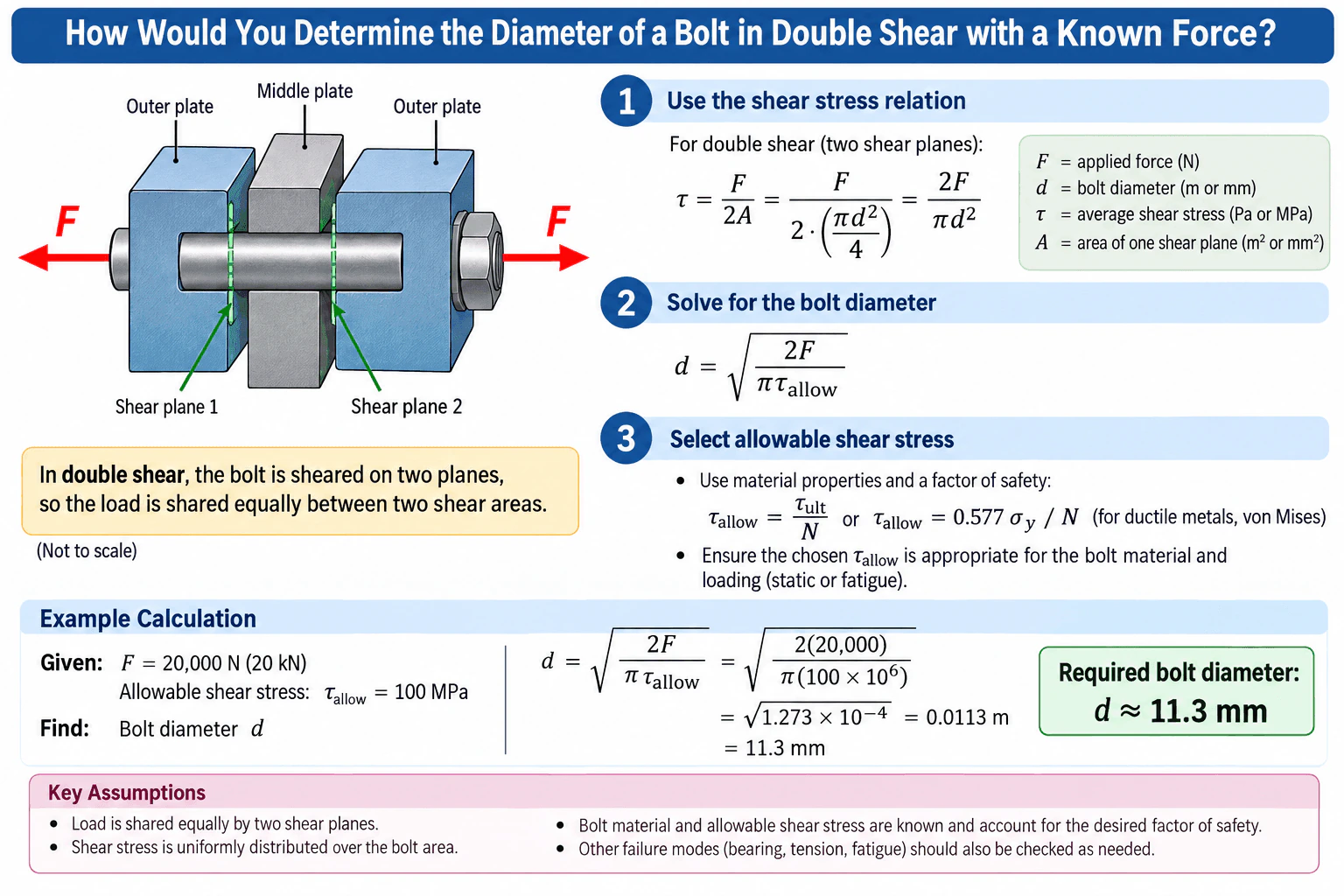
I would first identify the two shear planes through the bolt. For a circular bolt, one shear plane has area A = πd²/4, so double shear gives a total resisting area of 2A. The average shear stress is therefore τ = F/(2A) = 2F/(πd²). Setting that equal to the allowable bolt shear stress and solving gives d = √(2F/(πτ_allow)). I would calculate τ_allow from the applicable material strength and factor of safety, use consistent units, round the result up to an available bolt size, and then check bearing, tension, and fatigue if they are relevant.

Detailed Explanation

The key idea is that a bolt in double shear is cut across two potential shear planes, so the applied load is resisted by two bolt cross-sectional areas rather than one. Under the simplified assumptions of equal load sharing and uniform average shear stress, the total resisting shear area is twice the circular area of the bolt.

Let:

  • F = total applied shear force on the joint
  • d = bolt diameter
  • A = cross-sectional area of the bolt on one shear plane = πd²/4
  • τ = average shear stress
  • τ_allow = allowable shear stress for the bolt material

For two shear planes,

τ = F/(2A)

Substituting A = πd²/4 gives

τ = F/[2(πd²/4)] = 2F/(πd²).

For sizing, set the calculated average shear stress equal to the allowable value:

τ_allow = 2F/(πd²).

Solving for diameter gives

d = √(2F/(πτ_allow)).

The allowable shear stress must reflect the selected bolt material and the desired factor of safety. Depending on the material-property basis and design method, it may be expressed using an allowable based on ultimate shear strength, such as τ_allow = τ_ult/N, or for a ductile-metal yielding approximation using the von Mises relation, τ_allow = 0.577σ_y/N. The chosen relationship must be appropriate for the actual material, loading, and governing design requirements.

Useful Questions to Ask the Interviewer
  • Is F the total static shear force transmitted through the joint?
  • Can I assume the two shear planes share the force equally?
  • Is the bolt intended to be modeled in pure shear, with bending and prying neglected?
  • What bolt material or allowable shear stress should I use?
  • What factor of safety or governing design standard should be applied?
  • Is the load purely static, or do fatigue or cyclic-loading checks matter?
  • Should I also verify plate bearing, bolt tension, or combined loading?
How would you determine the diameter of a bolt in double shear with a known force? diagram
How to Explain It in an Interview

I would start by defining the free-body boundary around the joint and identifying the two interfaces where the bolt can shear. In ideal double shear, those two planes share the total force equally, so each plane carries F/2. Because each plane cuts through the bolt cross section, each resisting area is πd²/4.

I would then write equilibrium through the shear resistance as F = 2τA. Substituting A = πd²/4 gives F = τπd²/2, which rearranges to d = √(2F/(πτ)). For design, I replace τ with the allowable shear stress τ_allow.

As an illustrative calculation consistent with the approved diagram, suppose F = 20,000 N and τ_allow = 100 MPa = 100 × 10⁶ N/m². Then

d = √[2(20,000)/(π(100 × 10⁶))] = √(1.273 × 10⁻⁴) ≈ 0.0113 m ≈ 11.3 mm.

So the simplified shear calculation requires a bolt diameter of at least about 11.3 mm before selecting an appropriate available size and completing the remaining design checks.

I would also state the assumptions: the load is shared equally between the two shear planes, shear stress is represented by its average value over the bolt area, the bolt is treated primarily in shear, and the material allowable already incorporates the selected strength basis and factor of safety. If joint geometry causes unequal load sharing, bolt bending, prying, combined tension and shear, or cyclic loading, the simple double-shear equation is no longer sufficient by itself.

Finally, I would verify the units and limiting behavior. F divided by stress has units of area, and the square root therefore produces a length. A larger force requires a larger diameter, while a higher allowable shear stress permits a smaller calculated diameter. Before using the result in a real design, I would also check relevant failure modes such as plate or bolt bearing, bolt tension, fatigue under cyclic loading, and any geometry- or standard-specific requirements.

Technical Approach
  1. Define the joint free-body boundary and identify the total applied shear force F.
  2. Confirm that the bolt is in double shear, giving two resisting shear planes.
  3. State the assumptions: equal load sharing between the planes, average uniform shear stress, and no significant bolt bending or prying for the simplified calculation.
  4. Define the area on one shear plane as A = πd²/4.
  5. Write the average shear-stress relation for double shear: τ = F/(2A).
  6. Substitute the circular area to obtain τ = 2F/(πd²).
  7. Determine an appropriate allowable shear stress τ_allow from the bolt material strength and required factor of safety.
  8. Solve for the required diameter: d = √(2F/(πτ_allow)).
  9. Substitute values using one consistent unit system and check dimensional consistency.
  10. Round the calculated requirement upward when selecting an available bolt size.
  11. Verify additional relevant limit states such as bearing, bolt tension, combined loading, and fatigue before treating the joint design as complete.
Practical Insights

The basic calculation is simple, but the engineering judgment is in choosing the correct allowable shear stress and deciding whether the ideal double-shear assumptions are valid. Increasing bolt diameter lowers average shear stress because the resisting area grows with d². A stronger bolt material can reduce the diameter required by the simplified shear calculation, but joint geometry, bearing area, available standard sizes, fatigue, bolt tension, and manufacturing constraints can govern instead. Unequal shear-plane loading or bolt bending also makes the simple equal-sharing model less accurate.

Why Interviewers Ask This

This tests whether the candidate can translate a physical joint into the correct free-body and stress model, recognize that double shear provides two resisting shear planes, manipulate the shear-stress equation correctly, use material strength and factor of safety appropriately, maintain consistent units, state simplifying assumptions, and recognize that a shear calculation alone does not complete a real joint design.

Common interview mistakes

Common mistakes include treating double shear as single shear and using only one bolt area; dividing the force by two and then accidentally dividing by two again; using πd² instead of πd²/4 for the circular cross-sectional area; confusing allowable shear stress with tensile yield or ultimate strength without an appropriate conversion or design basis; mixing N with MPa or m with mm inconsistently; assuming equal load sharing when the geometry produces eccentricity or bending; reporting the exact calculated diameter without rounding up for selection; and stopping after the shear calculation without checking bearing, tension, combined loading, or fatigue when those modes are relevant.

Interview tip

Start with the physical picture: two shear planes means two resisting bolt areas. Then write F = 2τA, define A = πd²/4, and solve symbolically before inserting numbers. State your assumptions and allowable-stress basis explicitly. After finding d, mention that the calculated value is a minimum from the simplified shear model and that a real design still requires selection of an available bolt and verification of the other applicable joint failure modes.

Interviewer may ask next
What would you verify if the two shear planes do not share the load equally?

I would not use F/2 on each plane automatically. I would examine the joint geometry, stiffness, clearances, eccentricity, plate arrangement, and contact conditions to determine how the load is actually distributed. If one shear plane can carry a larger portion of the load, I would size the bolt using the maximum credible force on that plane and also check bolt bending and bearing. For a complex or highly loaded joint, a more detailed analytical or validated numerical model may be needed instead of the ideal equal-sharing assumption.

How would the required diameter change if the joint were in single shear instead of double shear?

In single shear there is only one resisting bolt area, so τ = F/A = 4F/(πd²). Solving for diameter gives d = √(4F/(πτ_allow)). For the same total force and allowable shear stress, the ideal single-shear diameter is √2 times the ideal double-shear diameter because the single-shear joint has only half as much resisting shear area.

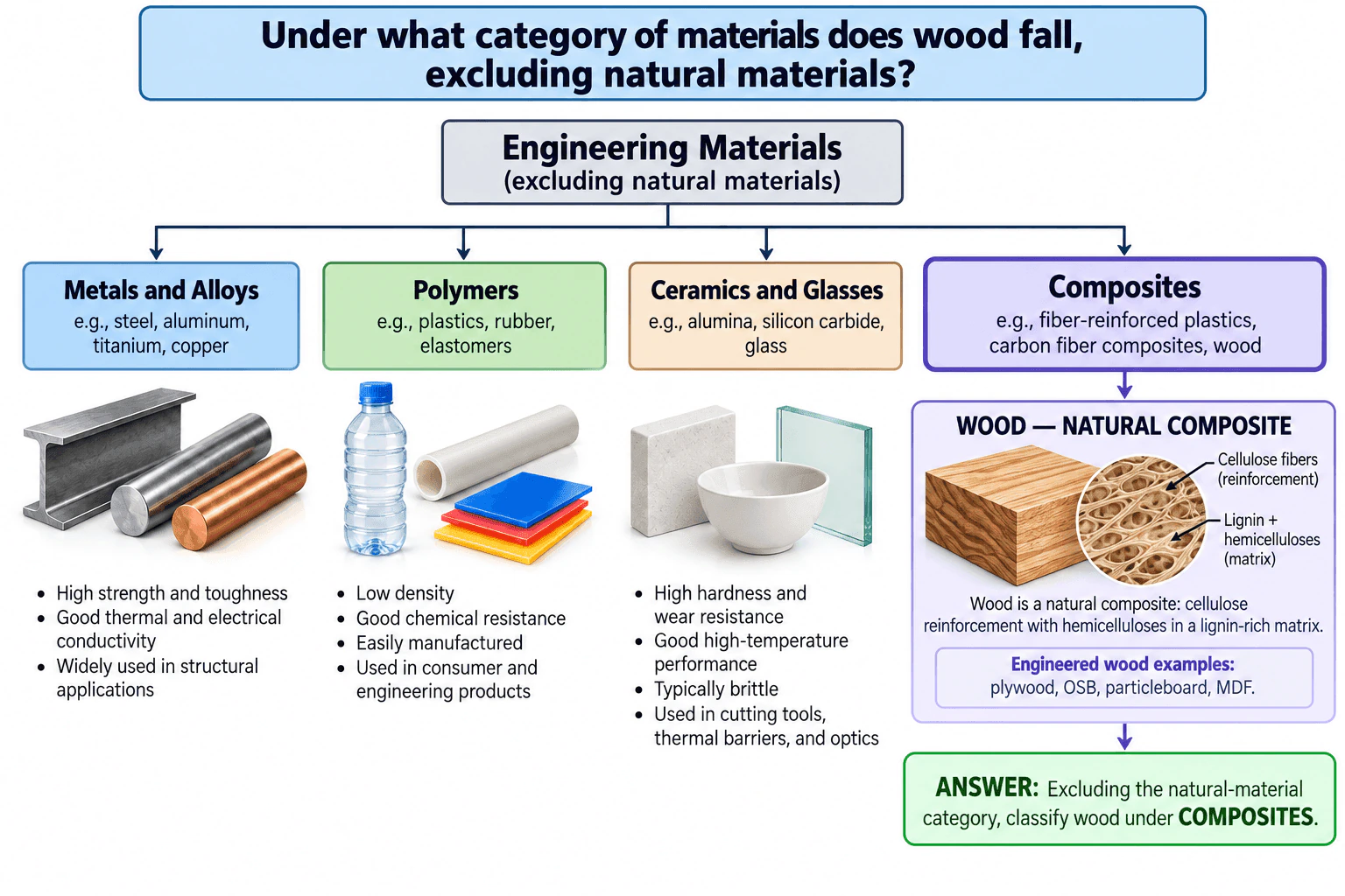
5. Under what category of materials does wood fall, excluding natural materials?Materials And Material SelectionEasyTesla

Short Interview Answer (30-60 seconds)

Excluding the natural-material category, wood falls under composites. Wood is itself a natural composite: cellulose provides the reinforcing structure, while hemicelluloses are present within a lignin-rich matrix. That combination of distinct constituents working together is the key reason it fits the composite category. Engineered wood products such as plywood, OSB, particleboard, and MDF are also examples of wood-based composite materials.

Detailed Explanation

Wood is normally recognized as a natural material, but if the natural-material category is excluded, the best engineering classification is composites. The reason comes from its internal structure. Wood is a natural composite in which cellulose provides reinforcement, with hemicelluloses present in a lignin-rich matrix. These constituents perform different structural roles but work together as one material.

The other broad material families shown in the classification are less appropriate. Wood is not a metal or alloy, and it is not a ceramic or glass. Although cellulose, hemicelluloses, and lignin are natural polymers, classifying wood simply as a polymer would miss its reinforced, multi-constituent structure. Looking at the material as a structural system, composite is the most useful classification when natural materials are excluded.

Engineered wood products reinforce this concept. Plywood, oriented strand board (OSB), particleboard, and medium-density fiberboard (MDF) are wood-based composite products made by combining wood elements with bonding and consolidation processes.

Useful Questions to Ask the Interviewer
  • Are you asking for the broad engineering-material category after excluding natural materials?
  • Do you mean natural solid wood, or an engineered wood product such as plywood, OSB, particleboard, or MDF?
Under what category of materials does wood fall, excluding natural materials? diagram
How to Explain It in an Interview

Start with the direct answer: excluding natural materials, classify wood under composites. Then justify it from structure. Cellulose acts as the reinforcing phase, while hemicelluloses are present within a lignin-rich matrix. Those constituents perform different roles but act together as one material, which is the defining idea behind a composite. Then distinguish wood from metals, polymers, and ceramics, and mention engineered wood examples such as plywood, OSB, particleboard, and MDF. No numerical property comparison is necessary for this question because the classification follows from material structure rather than a specified load, operating temperature, corrosion environment, or manufacturing requirement.

Technical Approach
  1. Identify the allowed material families after excluding the natural-material category.
  2. Examine the material's internal structure rather than only its common name.
  3. Determine whether multiple constituents perform different structural roles.
  4. Recognize cellulose as the reinforcing phase, with hemicelluloses present in a lignin-rich matrix.
  5. Compare that structure with the defining concept of a composite material.
  6. Conclude that composites are the best remaining category for wood.
Practical Insights

This classification does not require a numerical calculation. The main tradeoff is how broadly the material families are defined. Calling wood simply a polymer misses its hierarchical, reinforced structure, while calling it only a natural material does not answer the question once that category is excluded. For real material selection, additional factors such as anisotropy, moisture sensitivity, density, strength, stiffness, temperature exposure, processing compatibility, availability, durability, and end-of-life requirements would matter.

Why Interviewers Ask This

This checks whether the candidate understands basic engineering-material classification and can classify a material from its structure rather than relying only on familiar labels. The key judgment is recognizing that wood contains distinct structural constituents that work together, which makes composite the appropriate category when the separate natural-material category is excluded.

Common interview mistakes

A common mistake is answering only 'natural material' even though the question explicitly excludes that category. Another is classifying wood simply as a polymer because cellulose, hemicelluloses, and lignin are polymers. That ignores the way these constituents form a reinforced composite structure. It is also a mistake to imply that all wood is engineered wood; natural solid wood is itself a natural composite, while plywood, OSB, particleboard, and MDF are engineered wood products.

Interview tip

Answer 'composite' first, then justify it in one sentence using structure: cellulose acts as reinforcement, with hemicelluloses present in a lignin-rich matrix. That shows you understand why the classification applies rather than merely memorizing the category.

Interviewer may ask next
How would you validate the classification if there were ambiguity about what the interviewer means by wood?

I would first clarify whether they mean natural solid wood or an engineered wood product. For natural wood, I would classify it as a natural composite based on its cellulose reinforcement, hemicelluloses, and lignin-rich matrix. For engineered products such as plywood, OSB, particleboard, or MDF, I would describe the specific wood elements and bonding system used to create the engineered composite.

Would the answer change if natural materials were allowed as a separate category?

Yes. At the highest classification level, wood could simply be placed under natural materials. At the structural level, however, wood can still be described as a natural composite. The preferred label therefore depends on the classification hierarchy being used.

6. How do you decide if a battery pack needs cooling?Thermodynamics And Heat TransferMediumTesla

Short Interview Answer (30-60 seconds)

I would compare battery heat generation with the pack's ability to reject heat under the expected operating conditions. I define the pack as the thermal system and use an energy balance such as m·cp·dT/dt = Q̇gen − Q̇out. I check both the hottest-cell temperature and temperature differences across the pack during charging, discharging, hot ambient conditions, and repeated high-load operation. If passive heat rejection through conduction, convection, and radiation cannot maintain the applicable thermal limits with appropriate engineering margin, then the pack needs active cooling. I would confirm that conclusion with a thermal model and representative testing.

Detailed Explanation

A battery pack needs cooling when the heat generated inside the cells cannot be rejected quickly enough to keep every cell within its allowable temperature range and within an acceptable temperature spread across the pack.

The first step is to define the thermal system boundary. I would normally treat the cells, modules, structural interfaces, enclosure, and any cooling hardware inside the chosen boundary as the battery thermal system. Heat generated inside the cells is positive into that thermal system, while heat leaving through conduction, convection, radiation, or a coolant circuit is positive out.

For a transient condition, a useful first-law energy balance is:

m·cp·dT/dt = Q̇gen − Q̇out

where m is the effective thermal mass in kg, cp is the effective specific heat in J/(kg·K), T is temperature, Q̇gen is internal heat generation in W, and Q̇out is heat rejected from the pack in W. Temperature differences may be expressed in K or °C because their increments are equal.

At steady state, dT/dt = 0, so the balance becomes approximately:

Q̇gen = Q̇out

The decision is therefore not based only on whether the battery produces heat. Batteries generate heat during operation, but the important question is whether the available heat-rejection paths can remove that heat fast enough over the required operating duty.

Battery heat generation depends on operating current, internal resistance, electrochemical behavior, cell temperature, state of charge, and operating mode. A simple first estimate may include irreversible resistive heating using Q̇ ≈ I²R, but that is not necessarily the complete cell heat-generation model. For a real pack, I would use applicable cell-manufacturer data, calorimetry data, or a validated electrothermal model when reversible or other electrochemical heat terms are significant.

I would then model how heat leaves the cells. Conduction moves heat through cell structures, tabs, module structures, thermal interface materials, cold plates, and enclosure components. Convection removes heat from surfaces to air or liquid coolant. Radiation can also exchange heat with surrounding surfaces. If radiation is modeled explicitly, absolute temperature in kelvin is required, for example Q̇rad = εσA(Ts⁴ − Tsur⁴). In many compact battery systems, conduction and forced convection dominate, but that should be checked rather than assumed.

Each thermal path can be represented with an appropriate thermal resistance when that simplification is valid. For convection:

Rconv = 1/(hA)

where h is the convective heat-transfer coefficient in W/(m²·K) and A is the effective heat-transfer area in m².

For one-dimensional conduction through a flat layer:

Rcond = L/(kA)

where L is layer thickness in m and k is thermal conductivity in W/(m·K).

For a simplified thermal path, the temperature difference can then be related to heat flow by:

ΔT = Q̇·Rth

This provides an early estimate of whether passive heat rejection is likely to be sufficient.

I would evaluate several operating conditions rather than one nominal point. Important cases include sustained high discharge, fast charging, repeated acceleration or other high-power events, high ambient temperature, reduced airflow when air cooling is used, heat soak after operation, and any duty cycle that can produce cumulative temperature rise. Transient behavior matters because a pack may tolerate a short heat pulse even when that same heat-generation rate would be unacceptable if sustained.

The decision criteria should come from the allowable operating limits for the actual cells and pack design. I would check at least the hottest-cell temperature and cell-to-cell temperature variation. Minimum cell temperature can also matter to the overall thermal-management strategy, especially for charging, although it is not normally the limiting criterion for deciding whether heat must be removed. A pack can have an acceptable average temperature while still containing local cells that are too hot, so temperature uniformity matters.

I would also consider uncertainty. Cell resistance can vary with aging, state of charge, temperature, and manufacturing variation. Thermal interface resistance can vary because of contact pressure, flatness, assembly tolerance, and material condition. Cooling performance can change with coolant flow, airflow, blockage, pump or fan performance, and environmental conditions. Therefore, the cooling decision should include appropriate engineering margin rather than being based on a single ideal calculation.

If passive heat rejection keeps all cells within their required thermal limits throughout the operating envelope, active cooling may not be necessary. If the predicted or measured hottest-cell temperature exceeds an allowable limit, temperature gradients become excessive, or the pack accumulates heat during repeated operation faster than it can reject it, I would introduce or increase active cooling. Depending on the application, that could involve forced air, a liquid cold plate, a refrigerant-coupled system, or another controlled thermal path.

When evaluating an active cooling concept, I would also check the cooling-side energy balance. For a single-phase liquid coolant, the removed heat can be estimated as:

Q̇coolant = ṁcoolant·cp,coolant·(Tout − Tin)

where ṁcoolant is coolant mass flow rate in kg/s, cp,coolant is coolant specific heat in J/(kg·K), and Tin and Tout are coolant inlet and outlet temperatures. This provides a physical check that the proposed coolant flow and temperature rise are consistent with the required heat-removal rate.

Validation is essential before implementation. I would instrument representative cells at predicted hot spots and cooler locations, measure inlet and outlet coolant or air temperatures when applicable, record electrical current and voltage, and compare measured transient temperatures with the model. I would test representative duty cycles and environmental conditions and investigate meaningful model-to-test mismatch before relying on the model for final design decisions.

Useful Questions to Ask the Interviewer
  • What cell chemistry and cell format are being used?
  • What temperature limits and preferred operating range are specified for the cells and pack?
  • What are the maximum continuous and transient charge and discharge currents?
  • What is the expected duty cycle rather than just the peak current?
  • What ambient-temperature range must the battery operate in?
  • Is the main concern maximum temperature, cell-to-cell uniformity, battery life, charging performance, or all of these?
  • What passive thermal paths already exist through the enclosure and surrounding structure?
  • Is forced air, liquid cooling, or refrigerant cooling available?
  • Are there constraints on pumping power, fan power, mass, packaging space, noise, cost, or serviceability?
  • What thermal test data or validated cell heat-generation data are available?
How to Explain It in an Interview

I would explain that I do not decide whether cooling is needed simply by looking at battery electrical power. I first determine or estimate the heat-generation rate, define the thermal paths from the cells to the surroundings, and perform a transient energy balance. Then I predict the hottest-cell temperature and temperature spread during the most demanding realistic operating conditions. If passive cooling cannot maintain the required thermal limits and temperature uniformity with suitable engineering margin, I would select active cooling and determine the required heat-removal capacity. Finally, I would validate the model with instrumented pack testing because local hot spots, contact resistance, cell variation, and real coolant or airflow behavior can make the physical system differ from a simplified model.

Technical Approach
  1. Define the thermal system boundary around the battery cells, modules, enclosure, and relevant cooling components.
  2. Identify the applicable cell and pack temperature limits and allowable temperature variation.
  3. Define the operating envelope, including ambient temperature, charge and discharge current, duty cycle, duration, and repeated-load conditions.
  4. Estimate or obtain cell heat generation as a function of current, state of charge, temperature, and operating mode using appropriate cell data or a validated model.
  5. Identify the heat-rejection paths: conduction, convection, radiation, and any active coolant circuit.
  6. Build a thermal-resistance model or higher-fidelity thermal model appropriate to the design stage.
  7. Apply the transient energy balance m·cp·dT/dt = Q̇gen − Q̇out for time-varying conditions and the steady-state balance Q̇gen = Q̇out only when steady-state assumptions are justified.
  8. Predict the hottest-cell temperature and cell-to-cell temperature spread for the critical operating cases.
  9. Compare those predictions with the applicable thermal limits while accounting for uncertainty and engineering margin.
  10. If passive heat rejection is insufficient, evaluate active-cooling options and estimate the required heat-removal capacity and coolant or airflow conditions.
  11. Check energy conservation and physical feasibility on both the battery and cooling sides.
  12. Validate the model with instrumented thermal testing over representative duty cycles and environmental conditions.
  13. Update the model and cooling design if measured temperatures, gradients, or heat rejection differ materially from predictions.
Practical Insights

The main tradeoff is between thermal performance and the penalties of adding a cooling system. More cooling capacity can reduce peak temperature and improve temperature uniformity, but it can add mass, packaging volume, electrical or mechanical power consumption, cost, controls, plumbing, leak risk, noise, and maintenance requirements. Passive cooling is simpler but depends strongly on available surface area, thermal interfaces, ambient conditions, and duty cycle. Forced-air systems can be relatively simple but may struggle with high heat flux or uniform cooling. Liquid cooling can remove more heat and often provide better temperature control, but it adds pumps, channels, seals, coolant, and system complexity. The analysis must also account for uncertainty in cell heat generation, cell resistance, thermal contact resistance, aging, heat-transfer coefficients, coolant or airflow distribution, and real operating conditions.

Why Interviewers Ask This

The interviewer is evaluating whether the candidate can turn a practical battery thermal-management question into a defensible engineering decision. That requires defining the thermal boundary, applying an energy balance, distinguishing transient from steady-state behavior, recognizing maximum temperature and temperature uniformity as separate concerns, accounting for uncertain heat generation and environmental conditions, and explaining how analysis would be validated before implementation.

Common interview mistakes

Common mistakes include deciding based only on peak electrical power instead of actual heat generation; using only a steady-state calculation for a strongly transient duty cycle; checking average pack temperature instead of the hottest cell; ignoring cell-to-cell temperature variation; assuming Q̇ = I²R is always a complete electrochemical heat model; using an unjustified convection coefficient; ignoring thermal contact resistance between cells, interfaces, and cold plates; using °C instead of absolute kelvin in radiation calculations; evaluating only one ambient condition; forgetting heat accumulation during repeated load cycles; failing to check whether the cooling-side mass flow and temperature rise can actually remove the required heat; treating a simplified thermal calculation as proof that a real pack is safe; and failing to validate the model with physical temperature measurements.

Interview tip

Start with the decision criterion: cooling is needed when available passive heat rejection cannot keep every cell within its required temperature limits and temperature-uniformity targets over the operating envelope. Then write the transient energy balance, explain where heat is generated and how it leaves the pack, distinguish short thermal pulses from sustained loads, check the hottest cell rather than only the average temperature, and finish with validation. That structure shows both thermodynamics knowledge and practical engineering judgment.

Interviewer may ask next
How would you validate your thermal model before approving the cooling concept?

I would instrument a representative battery assembly with temperature sensors at predicted hot spots, cooler locations, important interfaces, and relevant coolant or air inlet and outlet locations. I would record current, voltage, ambient conditions, coolant or airflow conditions, and transient temperatures during representative charge and discharge duty cycles. I would compare measured temperature rise, thermal time constants, hottest-cell location, and temperature spread with the model. If the disagreement is significant, I would investigate uncertain inputs such as heat generation, contact resistance, material properties, coolant or airflow distribution, and heat-transfer coefficients, update the model, and repeat the comparison. I would not treat agreement at only one operating point as sufficient validation for the full operating envelope.

What changes if the battery only experiences very high power for a few seconds at a time?

Then transient thermal capacity becomes much more important than steady-state cooling capacity. A short high-power event can produce a high instantaneous heat-generation rate without causing an excessive temperature rise because the cells and surrounding structure absorb part of that heat as stored thermal energy. I would use the transient energy balance and the expected repetition rate of the events rather than sizing cooling from peak heat generation alone. If enough time exists between events for the stored heat to be rejected, a smaller cooling system may be adequate. If the events repeat faster than the pack can reject the accumulated heat, the baseline temperature will rise and the pack can still exceed its allowable thermal limits.

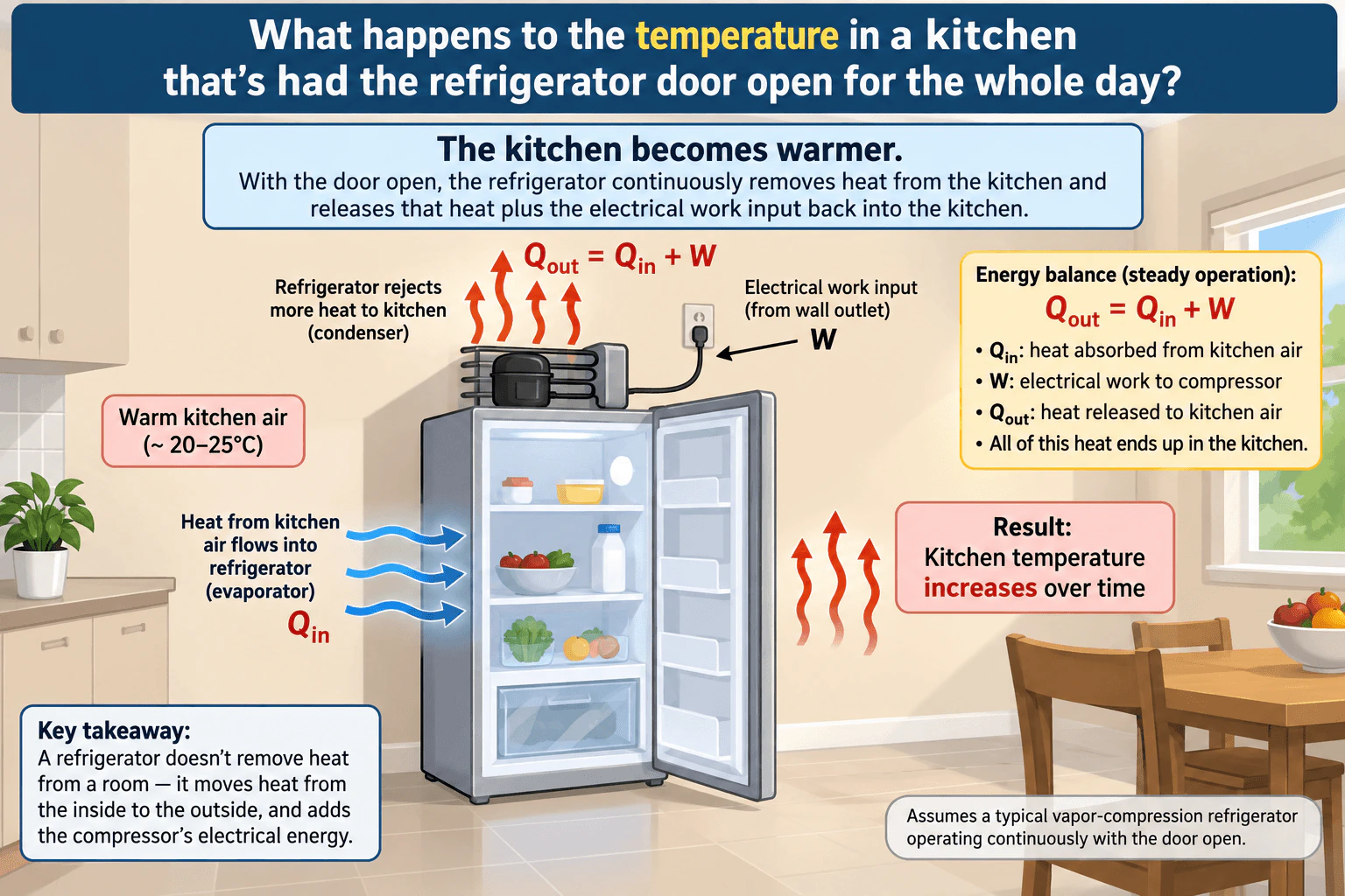
7. What happens to the temperature in a kitchen that's had the refrigerator door open for the whole day?Thermodynamics And Heat TransferEasyTesla

Short Interview Answer (30-60 seconds)

The kitchen gets warmer, not cooler. With the refrigerator door open, the evaporator absorbs heat Q_in from kitchen air, while the compressor adds electrical work W. The condenser rejects both back into the kitchen, so Q_out = Q_in + W. Because Q_in came from the same kitchen, it cancels when we consider the whole room. The net heat added is approximately the refrigerator's electrical work, so the kitchen temperature increases over time.

Detailed Explanation

The refrigerator does not destroy heat; it moves heat and requires work to do it. Assume a typical vapor-compression refrigerator operating with its door open and with both the evaporator and condenser thermally connected to the same kitchen.

Warm kitchen air reaches the evaporator, where the refrigerator absorbs heat Q_in. The compressor receives electrical work W from the wall outlet. The condenser then rejects heat Q_out back into the kitchen.

For a control volume around the refrigerator, take Q_in as heat absorbed at the evaporator, W as electrical work entering the compressor, and Q_out as heat rejected by the condenser. For approximately steady refrigerator operation, the first-law energy balance is:

Q_out = Q_in + W

Now expand the system boundary to include the entire kitchen and refrigerator. The heat Q_in came from the kitchen air and is returned to the kitchen through the condenser, so it is an internal energy transfer within this larger system. It does not represent a net loss of energy from the kitchen. The additional energy entering the kitchen is the compressor's electrical work W.

Therefore, the net effect of running the refrigerator with its door open is to add heat to the kitchen. The kitchen temperature rises with time compared with the same conditions with the refrigerator off.

The room itself is a transient system while its temperature is changing. As the kitchen warms, heat can leave through walls, windows, ventilation, radiation, and other paths, and an HVAC system may remove heat. If those losses eventually equal the added electrical power, the room can approach a new steady temperature. The exact final temperature cannot be calculated from the question alone because the refrigerator power history, room thermal mass, building heat-transfer characteristics, ventilation, outdoor conditions, and HVAC behavior are not specified.

No coefficient of performance is needed to determine the direction of the temperature change. COP describes how much heat the refrigerator moves per unit of work, but the conclusion remains the same when both sides of the refrigerator exchange heat with the same kitchen: the compressor work becomes a net heat input to the room.

Useful Questions to Ask the Interviewer
  • Should I assume a normal vapor-compression refrigerator operating continuously or nearly continuously with the door open?
  • Should I treat both the evaporator and condenser as being inside the same kitchen control volume?
  • Should I ignore HVAC and other heat losses for the conceptual conclusion, or discuss how they affect the eventual steady temperature?
What happens to the temperature in a kitchen that's had the refrigerator door open for the whole day? diagram
How to Explain It in an Interview

Start with the conclusion: the kitchen gets warmer. Then define a control volume around the refrigerator. The evaporator absorbs Q_in from kitchen air, the compressor adds electrical work W, and the condenser rejects Q_out = Q_in + W to the kitchen. Next expand the boundary to include the whole kitchen. Q_in is now only an internal transfer, so the net energy added by the refrigerator is approximately W. That extra energy causes the room temperature to rise over time, although heat losses or HVAC cooling may eventually create a new steady state.

Technical Approach
  1. Define a control volume around the refrigerator.
  2. Define Q_in as heat absorbed from kitchen air by the evaporator, W as electrical work entering the compressor, and Q_out as heat rejected by the condenser.
  3. Apply the first law for approximately steady refrigerator operation: Q_out = Q_in + W.
  4. Expand the system boundary to include the refrigerator and the entire kitchen.
  5. Recognize that Q_in is now an internal heat transfer because it originated in the kitchen and returns to the same kitchen.
  6. Cancel that internal transfer in the whole-kitchen energy balance.
  7. Identify the refrigerator's net contribution to the kitchen as approximately +W.
  8. Treat the kitchen temperature as transient while energy accumulates.
  9. Conclude that the kitchen becomes warmer, with any eventual steady temperature determined by the balance between the added electrical power and heat removed through the building envelope, ventilation, or HVAC.
Practical Insights

The direction of the effect is simple: the refrigerator adds net heat to the kitchen equal approximately to its electrical input. Predicting the exact temperature after a full day is more complicated because the kitchen is not perfectly insulated. Its temperature depends on the refrigerator's power and duty cycle, the thermal mass of the room and its contents, conduction through walls and windows, convection and ventilation, radiation, outdoor conditions, and any HVAC cooling. Those effects determine how quickly the room warms and whether it eventually reaches a higher steady temperature.

Why Interviewers Ask This

This question tests whether the candidate can choose the correct thermodynamic system boundary and apply the first law instead of assuming that an operating refrigerator automatically cools the surrounding room. It also checks whether the candidate understands that a refrigerator moves heat, requires compressor work, and can distinguish transient temperature rise from a possible later steady state.

Common interview mistakes

A common mistake is saying the kitchen becomes colder because cold air escapes from the refrigerator. That ignores the condenser heat and compressor work. Another mistake is treating Q_in and Q_out as separate external heat flows after expanding the boundary to include the whole kitchen; Q_in is then an internal transfer. It is also incorrect to say the temperature must rise forever at a constant rate. In a real kitchen, heat losses and HVAC response change as the room temperature changes, so the room may approach a higher steady temperature. Finally, a numerical temperature rise cannot be justified without refrigerator power, duty cycle, room thermal mass, heat-transfer paths, ventilation, outdoor conditions, and HVAC data.

Interview tip

State the answer first: the kitchen gets warmer. Then make the system boundary the center of the explanation. Show Q_out = Q_in + W for the refrigerator, expand the boundary to the whole kitchen, and explain that Q_in becomes an internal transfer. That immediately shows why the net energy added to the kitchen is approximately the compressor's electrical work.

Interviewer may ask next
What information would you need to estimate how many degrees the kitchen temperature rises after one day?

I would need the refrigerator's electrical power as a function of time or its average duty cycle, the thermal mass of the kitchen air and surrounding contents and structure, the initial indoor temperature, outdoor temperature history, wall and window heat-transfer characteristics, ventilation or infiltration rate, and any HVAC cooling response. I could then write a transient whole-room energy balance in which the rate of stored thermal energy equals refrigerator electrical input plus other heat gains minus heat losses and HVAC removal.

What changes if the refrigerator's condenser rejects heat outside the kitchen?

Then the result changes because Q_out leaves the kitchen instead of returning to it. The evaporator can remove Q_in from the kitchen while the condenser rejects Q_out = Q_in + W somewhere outside the kitchen. The kitchen therefore experiences a net cooling effect from the evaporator, subject to other heat gains and losses. This is the same basic arrangement used by an air conditioner or heat pump in cooling mode.

8. How does threading work with screws?Mechanical DesignEasyTesla

Short Interview Answer (30-60 seconds)

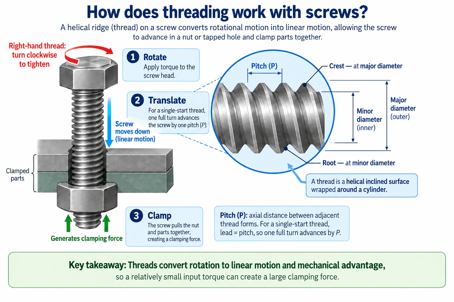
A screw thread is a helical inclined surface wrapped around a cylindrical shaft. When a right-hand screw is turned clockwise in the tightening direction, the helical geometry converts rotation into axial motion. For a single-start thread, one full revolution advances the screw by one pitch, so lead equals pitch. As the screw head or nut seats against the joint, continued tightening stretches the fastener and compresses the clamped parts, creating preload and clamping force. The crest of an external thread is at the major diameter, while the root is at the minor diameter. In a real joint, the achieved preload depends not only on thread geometry but also strongly on friction, joint stiffness, material, thread engagement, tolerances, and the tightening method.

Detailed Explanation

A screw works because its thread is a helix: an inclined surface wrapped around a cylinder. When the screw rotates relative to a matching internal thread in a nut or tapped hole, contact between the mating thread flanks forces relative motion along the screw axis. For the right-hand thread shown in the approved diagram, turning the screw clockwise in the tightening direction makes it advance into the mating thread.

For a single-start thread, the axial distance traveled in one complete revolution equals the pitch. Pitch, P, is the axial distance between corresponding points on adjacent thread forms. Lead, L, is the axial distance advanced in one full revolution. Therefore, for the single-start thread shown:

L = P

For a multi-start thread, the more general relationship is L = nP, where n is the number of thread starts.

The thread geometry also has important diameters. On an external thread, the crest lies at the major diameter and the root lies at the minor diameter. Pitch, major diameter, minor diameter, thread form, and engagement must be compatible with the mating internal thread.

The screw does more than create translation. Before the joint is seated, rotation mainly causes axial advance. Once the screw head or nut seats against the clamped parts, additional tightening elastically stretches the fastener and compresses the joint members. This creates bolt preload and the clamping force that holds the parts together. The thread provides mechanical advantage, so a relatively modest input torque can produce a much larger axial clamping force. However, the exact torque-to-preload relationship is strongly affected by friction at the threads and at the bearing surface under the screw head or nut.

Useful Questions to Ask the Interviewer
  • Are we discussing a conventional right-hand, single-start fastening thread? That matters because tightening direction and the relationship between lead and pitch depend on thread handedness and the number of starts.
  • Is the screw engaging a nut or a tapped hole? That changes how thread engagement, stripping risk, assembly access, and serviceability are evaluated.
  • Is the question mainly about how the thread creates motion, or should I also discuss clamping preload and joint design?
  • Are there specified loads, materials, thread standards, environmental conditions, or service requirements? Without those inputs, I would not invent a torque value, preload, engagement length, safety factor, or material property.
How does threading work with screws? diagram
How to Explain It in an Interview

Design Path:

  1. Start with the interface. The screw has an external helical thread that mates with an internal thread in a nut or tapped hole.
  2. Apply rotation. Torque is applied to the screw head or nut.
  3. Convert rotation to translation. The helical thread surfaces force axial motion as the two mating threads rotate relative to each other.
  4. Define pitch and lead. Pitch, P, is the axial spacing between adjacent thread forms. Lead, L, is the axial travel per revolution. For the single-start thread shown, L = P.
  5. Explain handedness. For the right-hand thread shown, clockwise rotation in the tightening direction advances the screw into the mating thread.
  6. Explain clamping. After the joint seats, continued tightening stretches the fastener and compresses the clamped parts, producing preload and clamping force.
  7. Connect the geometry to the thread. The crest of the external thread lies at the major diameter, while the root lies at the minor diameter.

Design Rationale: A thread behaves like a helical inclined surface wrapped around a cylinder. The long rotational path is converted into a smaller axial movement, which provides mechanical advantage. That is why relatively modest tightening torque can generate substantial clamping force. The geometry alone does not determine the final preload because friction, joint stiffness, material behavior, surface condition, lubrication, engagement, and tightening method also influence the result.

Design Checks:

  • Verify that the external and internal threads have compatible pitch, diameter, thread form, handedness, and tolerance class.
  • Verify adequate thread engagement so the mating threads do not strip under the required load.
  • Check the fastener for tensile loading and the joint for compression, separation, slip, fatigue, or other relevant load cases.
  • Consider manufacturing tolerances and surface condition because they affect fit and assembly.
  • Consider access for installation, tightening, inspection, and removal when serviceability matters.
  • Treat torque as an indirect method of creating preload because friction causes variation in the resulting clamping force.
  • Validate the actual fastener, mating thread, materials, surface condition, lubrication state, and assembly procedure under representative loading before approving a real design.

Relevant failure modes include thread stripping from inadequate engagement or weak mating material, fastener tensile failure from excessive preload or external load, preload loss or loosening under vibration or joint settlement, fatigue under cyclic loading, galling or seizure in susceptible material combinations, and joint separation when preload is insufficient.

The key idea is that the helical thread converts rotation into axial motion. For the single-start thread shown, one full turn advances the screw by one pitch. Once the joint is seated, further tightening develops preload and clamping force between the joined parts.

Practical Complexity & Trade-offs

The main tradeoffs are motion per turn, strength, assembly speed, manufacturability, and preload control. A finer pitch gives less axial travel per revolution and can provide finer adjustment, while a coarser pitch advances faster during assembly. Thread size, engagement, material, and tolerances must be selected so the mating threads fit reliably and resist stripping. Tightening torque is convenient, but friction creates uncertainty in actual preload, so critical joints may need a more controlled preload method. Manufacturing cost, accessibility, surface condition, galling risk, maintainability, and ease of disassembly can also affect the final thread and fastener choice.

Why Interviewers Ask This

Interviewers ask this to check whether you understand how a basic threaded fastener converts rotational motion into controlled axial motion and then into clamping preload. They also want to see whether you can explain practical thread geometry, distinguish pitch from lead, recognize thread handedness, and connect those ideas to mechanical-design concerns such as preload, friction, tolerances, manufacturing, assembly, and failure modes.

Interviewer may ask next
How would you validate that a threaded joint produces the intended clamping force?

I would first define the required preload range from the joint load cases and the need to prevent separation or slip. Then I would specify the actual fastener, mating thread, materials, engagement, surface condition, lubrication state, and tightening method. Because torque is affected strongly by friction, I would validate the assembly process using a preload measurement method appropriate to the application, such as measured bolt elongation or a calibrated tension-measuring setup. I would also inspect for thread damage or stripping and test representative joints under the relevant static, cyclic, vibration, thermal, and environmental conditions. I would not declare the joint safe from a torque calculation alone.

What changes if the screw uses a multi-start thread instead of a single-start thread?

For a multi-start thread, lead is greater than pitch. If there are n thread starts, the relationship is L = nP, so the screw advances farther during each revolution even though the pitch between adjacent thread forms remains P. That gives faster axial travel, but it also changes the helix geometry and mechanical advantage. The designer would need to reconsider torque, self-locking behavior, strength, manufacturability, engagement, and whether the faster travel is appropriate for the application.

9. How can you design an air suspension system?Mechanical DesignHardTesla

Question Details

Describe your approach to designing the air-suspension system.

Short Interview Answer (30-60 seconds)

I would start with vehicle load cases, target ride-height range, packaging and ground-clearance limits, ride and handling targets, operating environment, and service requirements. For each corner, I would derive the design vertical load and use the air spring's effective area to establish the required working-pressure range while staying within component ratings. The pneumatic path is intake filter to compressor and dryer, reservoir, fill/exhaust solenoid valve, and air spring. Height sensors feed the suspension ECU, which controls the compressor and valve to add or exhaust air and maintain target ride height. The damper controls suspension motion. I would then check mounts, seals, lines, materials, fatigue, leakage, thermal effects, assembly and service access, followed by pressure, leak, environmental, durability, load-leveling, ride, and fault validation.

Detailed Explanation

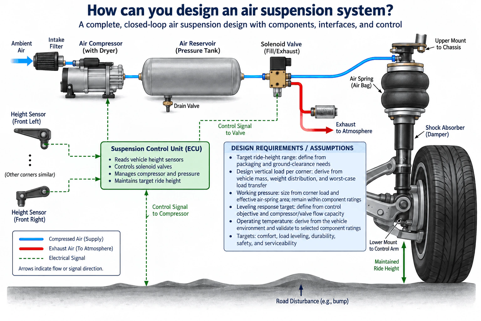
An air suspension system is a closed-loop mechanical and pneumatic system. The air spring supports the vehicle's vertical load with compressed air, the damper controls suspension motion, and the control system changes the mass of air in the spring to maintain the requested ride height as vehicle load or operating conditions change.

I would define the physical system boundary from ambient air to the suspension corner. The pneumatic path is ambient air → intake filter → compressor with dryer → air reservoir → fill/exhaust solenoid valve → air spring. When lowering is commanded, the solenoid valve provides an exhaust path from the air spring to atmosphere. The main mechanical interfaces are the upper mount to the chassis and the lower connection to the suspension structure. Height sensors measure suspension position, and the suspension control unit uses those signals to command the valve and compressor.

Useful Questions to Ask the Interviewer
  1. What vehicle mass, weight distribution, passenger or cargo conditions, and worst-case load-transfer cases must the suspension support?
  2. What nominal ride height and allowable ride-height range are required, and what packaging, ground-clearance, jounce, and rebound limits constrain that range?
  3. What ride-comfort and handling targets must the air spring and damper achieve?
  4. What leveling response is required after a load change, and is the system intended only for load leveling or also for commanded ride-height adjustment?
  5. What packaging space is available for the air spring, compressor, dryer, reservoir, valve, sensors, pneumatic lines, and service access?
  6. What temperature, contamination, water, corrosion, vibration, and durability environments apply?
  7. What degraded behavior is required after a compressor failure, sensor fault, valve fault, pneumatic leak, or loss of electrical control?
How can you design an air suspension system? diagram
How to Explain It in an Interview

First, I would convert vehicle requirements into corner load cases. For each suspension corner, I would determine the design vertical force from vehicle mass, static weight distribution, payload, and the relevant worst-case load-transfer condition. I would not assume a universal corner load because that value depends on the vehicle and operating case.

Next, I would size the air spring. A useful first-order relationship is

F ≈ P_g A_eff,

where F is the supported vertical force, P_g is the effective gauge pressure acting relative to ambient pressure, and A_eff is the effective air-spring area at the operating position. The actual effective area can change with spring geometry and stroke, so final sizing should use validated air-spring characteristics rather than assuming a constant area. I would select the air spring so the required loads and ride-height range remain within its approved pressure, stroke, temperature, articulation, and durability limits with appropriate design margin.

The amount of enclosed air and the spring geometry also affect vertical stiffness. Changing the air-spring volume or effective area changes the spring-rate behavior, so there is a tradeoff among load capacity, ride comfort, suspension travel, packaging, and natural frequency. The damper is then selected and tuned to control body and wheel motion; the air spring provides spring force but does not replace the need for damping.

For the pneumatic supply, ambient air passes through the intake filter to the compressor and dryer. The dryer reduces moisture entering the pneumatic system. Compressed air is stored in the reservoir so every leveling event does not require an immediate compressor start. The reservoir includes the shown drain provision for moisture management. I would size compressor capacity, reservoir volume, pneumatic line flow area, fittings, and valve flow from the required working-pressure range, air consumption, leveling-response target, expected compressor duty, and leakage allowance. These values must be derived from the actual vehicle requirements rather than assumed.

The fill/exhaust solenoid valve controls air flow to the air spring. To raise the suspension corner, the ECU commands the fill path so compressed air flows from the reservoir toward the air spring. To lower the corner, the ECU commands the exhaust path so air leaves the spring and vents to atmosphere. In the hold condition, the pneumatic circuit must minimize unintended leakage so the vehicle can maintain height without continuous compressor operation.

For closed-loop control, each height sensor measures suspension position relative to its mechanical reference. The ECU compares measured ride height with the target and commands the solenoid valve to fill or exhaust the air spring. The ECU also controls compressor operation as required to maintain the available pneumatic supply. I would use suitable control hysteresis or a deadband so small sensor variations and minor suspension motions do not cause continuous valve cycling. The control strategy should also avoid treating a brief road disturbance, such as the bump shown in the diagram, as a persistent change in static ride height.

Mechanically, I would check the upper mount to the chassis and lower connection to the suspension structure under the governing load cases. I would evaluate the complete load path, local stresses, fatigue, attachment stiffness, fasteners, clearances throughout jounce and rebound, air-line routing, abrasion protection, and access for assembly and service. The air spring must not rub adjacent hardware or operate outside its allowed stroke or articulation.

Materials and sealing must account for repeated pressure cycling, road contamination, temperature changes, water, vibration, and corrosion. I would choose materials and protective finishes based on strength, fatigue resistance, corrosion resistance, temperature capability, manufacturability, mass, and cost. Pneumatic interfaces need compatible seals, suitable mating surfaces, controlled fits and tolerances where they affect sealing or assembly, and features that reduce the risk of seal damage or incorrect line installation.

I would perform a failure-mode review before finalizing the architecture. Important cases include an air leak, damaged pneumatic line, leaking air spring, stuck fill valve, stuck exhaust valve, compressor failure, dryer or moisture-management degradation, reservoir leakage, height-sensor failure, ECU or wiring failure, and damaged mechanical mounts. For each failure, I would evaluate detection, whether the affected corner can be isolated, whether ride height can be temporarily maintained, what degraded behavior is acceptable, and what service action is required. The exact safe-state strategy depends on the vehicle architecture and applicable safety requirements.

The main design tradeoffs are interconnected. A larger reservoir can reduce compressor cycling and provide more immediately available air, but it adds packaging volume, mass, and cost. Larger pneumatic passages or higher-flow valves can shorten leveling time but may increase noise and produce more abrupt height changes. Greater available pressure can increase force capability for a given effective air-spring area, but every pressure-containing component must remain within its rating. A larger effective air volume can soften the spring characteristic but consumes packaging space and changes transient behavior. Independently controlled corners can improve leveling capability but add valves, sensing, wiring, diagnostics, and failure modes.

I would validate the design in stages. Component and subsystem testing would cover pressure integrity, leakage, valve operation, compressor thermal duty, dryer performance, height-sensor behavior, reservoir integrity, and air-spring travel. Environmental validation would cover the specified temperature, contamination, corrosion, water, and vibration conditions. Vehicle testing would cover static load leveling, payload changes, ride-height accuracy, full jounce and rebound clearance, ride and handling, road disturbances, compressor cycling, noise, fault cases, and durability. Results that fail requirements or show inadequate margin would feed back into the air-spring sizing, valve or line sizing, mounts, materials, sealing, control calibration, or service design before design release.

The final design therefore starts from measurable requirements and load cases, sizes the air spring and pneumatic supply from those requirements, closes the loop with height sensing and ECU-controlled fill and exhaust operation, integrates robust mechanical and pneumatic interfaces, and proves the design through analysis, prototype testing, fault testing, and vehicle validation.

Practical Complexity & Trade-offs

The main challenge is balancing load capacity, ride comfort, leveling speed, durability, packaging, mass, energy use, cost, and serviceability. A larger air spring or reservoir may improve ride behavior or reduce compressor cycling but needs more space and may add mass. Larger valves and flow passages can level the vehicle faster but may increase noise and make height changes more abrupt. Higher pressure can support more load for a given effective area, but the air spring, reservoir, valve, lines, fittings, and seals must all remain within their ratings. More independent sensing and control can improve leveling capability but increases hardware, wiring, diagnostics, and failure modes. Validation is also important because pressure, leakage, fatigue, temperature, contamination, suspension travel, control behavior, and mechanical interfaces interact.

Why Interviewers Ask This

Interviewers want to see whether I can turn vehicle-level requirements into a complete mechanical system: define load cases and interfaces, size the air spring and pneumatic hardware, integrate height sensing and closed-loop control, understand sealing and serviceability, identify failure modes, make defensible tradeoffs, and define a validation plan without inventing unsupported design values.

Interviewer may ask next
How would you validate that the air suspension can maintain ride height under changing loads?

I would first define the required load cases, target ride height, and allowable height tolerance. On a bench or vehicle prototype, I would apply representative corner-load and payload changes and record height-sensor output, air-spring pressure where instrumented for development, valve commands, compressor operation, leveling time, and final ride height. I would repeat the tests across the defined environmental range and relevant initial pneumatic-supply conditions. I would also perform leak-down tests with the system commanded to hold height so I could separate pneumatic leakage from control error. Then I would introduce fault cases such as a failed compressor, sensor fault, valve fault, or leaking circuit and verify the intended degraded behavior. I would require repeatable performance across the defined operating envelope and durability testing rather than accepting one successful nominal test.

What would change if the customer required much faster ride-height adjustment?

I would first quantify the new response-time target because faster leveling requires greater pneumatic mass flow. I would reevaluate valve flow capacity, line and fitting pressure losses, reservoir usable air capacity, compressor output and thermal duty, and air-spring volume over the required stroke. Larger-flow valves or lines, more usable reservoir capacity, or a higher-capacity compressor might be needed, but those changes affect packaging, mass, noise, energy use, cost, and component ratings. I would also retune the control strategy so the faster pneumatic system does not overshoot the target height or react unnecessarily to short road disturbances. The revised design would then need new thermal, noise, durability, ride-height, and fault validation.

10. Are you comfortable with working long hours for months at a time?NEWBehavioralEasyTesla

Question Details

Discuss your willingness to work this sustained schedule.

Interview tip:

Use STAR to structure your answer: briefly explain the Situation and Task, make Action the most detailed part, and finish with the Result. For example, describe a demanding engineering period where you worked extended hours, managed your energy and priorities, communicated risks early, protected safety and quality, and helped the team maintain steady progress.

Situation

In a previous role, I supported a mechanical design effort that entered a very demanding phase before design release and physical validation. The team had several important issues to resolve, and the workload stayed high for an extended period.

Task

I was responsible for completing my design work, supporting reviews and testing, and responding quickly when problems appeared. I was comfortable working longer hours during that period, but I also needed to make sure fatigue did not reduce the quality or safety of my engineering decisions.

Action

I organized my work around the items that could block testing or affect safety first. At the start of each day, I identified the most important engineering decisions and handled those while I was fresh. I used checklists for calculations, drawings, and design changes so that long days did not lead to missed details. When test results showed a problem, I documented what we knew, discussed the likely causes with the team, and focused my effort on the highest risk areas instead of trying to solve everything at once. I also communicated early when a task needed more time or another review. I was willing to stay late and support the team when the schedule required it, but I did not treat long hours as a reason to skip verification or make rushed decisions. I also managed my rest outside work so I could maintain consistent judgment over the sustained schedule.

Result

We continued making steady progress through the demanding period and completed the required engineering work without lowering our review standards. The experience showed me that I can handle extended hours when a project truly requires them. It also taught me that sustained performance depends on good priorities, clear communication, and protecting safety and engineering quality even when the schedule is intense.

Why Interviewers Ask This

Interviewers ask this question to understand whether the candidate can handle a sustained high workload while still making reliable engineering decisions. A strong answer shows flexibility, endurance, realistic time management, and a commitment to safety and quality rather than simply agreeing to work unlimited hours.

Interviewer may ask next
How did you make sure long hours did not affect the quality of your engineering work?

I handled the highest risk decisions when I was most focused, used checklists for important calculations and design changes, and asked for another review when a decision had meaningful safety or performance impact. I also communicated when fatigue or workload could create unnecessary risk instead of pretending that every task could be completed safely at the same pace.

Would you be willing to work a similar sustained schedule again?

Yes. I am comfortable putting in extended hours during demanding periods when the work and schedule require it. I would use the same approach of setting clear priorities, communicating risks early, and protecting the quality of important engineering decisions so that I can contribute consistently throughout the period.

Disclaimer: This interview guide is for educational and informational purposes only. It is designed to help readers prepare, but it does not guarantee any interview result, hiring decision, offer, or outcome. Interview questions, hiring criteria, and preferred answers can vary by employer, interviewer, industry, location, and time. All answers, examples, and explanations in this guide are suggested examples for interview preparation, not definitive answers or instructions for professional practice. They are based on research and judgment, are provided without warranties of any kind, and should be adapted to the question, role, and applicable laws and professional requirements. Diagrams are simplified illustrations intended to highlight the main concepts and their relationships; actual situations, systems, and practices may be more complex. Alternative approaches may be equally valid or better suited to a particular question, context, or interviewer. To the fullest extent permitted by applicable law, the contributors and publisher are not liable for decisions made, actions taken, or losses incurred based on this guide.

State Laws and Professional Responsibilities: Laws and requirements governing an occupation vary by state and jurisdiction. You are responsible for checking the current laws, licensing requirements, and scope-of-practice rules that apply to your location and role, and for ensuring that your answers and actions comply with them. Adapt examples in this guide to those requirements. This guide is not legal advice.

Company Notice: This guide is an independent educational resource and is not affiliated with, endorsed by, sponsored by, or approved by the company named in this guide. Company names identify reported interview experiences or the employer context of clearly labeled original practice exercises. Interview practices can change without notice, and inclusion of company-specific content does not mean these questions are official, complete, or guaranteed to be asked. To the fullest extent permitted by law, the author, contributors, and publisher are not responsible for outcomes related to use of this material.

Content Accuracy and Verification: To the fullest extent permitted by applicable law, we do not represent or warrant that interview guides, questions, answers, examples, or diagrams are accurate, complete, current, error-free, or suitable for any particular purpose. You are responsible for independently reviewing and verifying the information before relying on it.