12 Honeywell Mechanical Engineer Interview Questions & Answers

honeywell icon

Questions with Detailed ExplanationsWith Detailed Explanations

(Last Updated: September 13, 2026)

1. How would you increase the strength of a cantilever beam?NEWEngineering MechanicsMediumHoneywell

Short Interview Answer (30-60 seconds)

I would start at the fixed support because that is where a cantilever with an end load has its largest bending moment. For a static end load P on span L, M_max = PL and V_max = P. I can increase bending capacity by increasing the section modulus S, for example with a deeper or more efficient section, because sigma_max = M_max/S. I can also use a material with higher allowable strength, reduce P or its moment arm, shorten L, or add a brace or second support if a boundary-condition change is allowed. I would check shear separately because increasing section modulus alone does not guarantee lower shear stress.

Detailed Explanation

The basic idea is to either increase the beam's capacity or reduce the demand placed on it. Assume a prismatic rectangular cantilever, linear-elastic behavior, and a static downward point load P at the free end. Let L be the cantilever span. The critical location is the fixed support, where the bending moment is largest. For this loading, M_max = PL and V_max = P. The maximum bending stress is sigma_max = M_max/S = PL/S, where S = I/c is the section modulus. For a rectangular section of width b and depth h, S = bh^2/6 and A = bh. The rectangular-section maximum shear stress is tau_max = 3V_max/(2A) = 3P/(2A).

Useful Questions to Ask the Interviewer
  • Is the goal to increase allowable load capacity, reduce stress or deflection, or both?
  • Is the beam geometry fixed, or can its depth, width, cross-sectional shape, or span change?
  • Can the material be changed, and what strength, fatigue, temperature, corrosion, or weight constraints apply?
  • Is the loading truly static, or are there cyclic, impact, vibration, or fatigue effects that must also be considered?
  • Is the cantilever boundary condition fixed, or is adding a brace or second support acceptable?
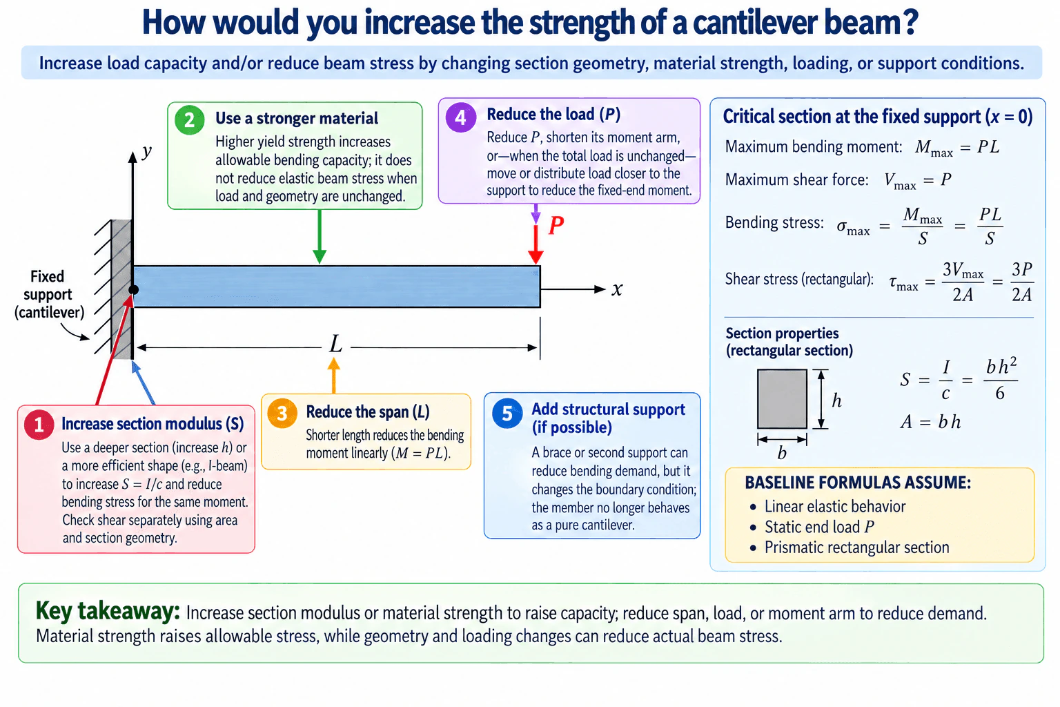
How would you increase the strength of a cantilever beam? diagram
How to Explain It in an Interview
  1. Start with the free-body model. Treat the wall as the fixed boundary, the free-end force as P, and the distance from the support to the force as L. Static equilibrium gives a support shear of magnitude P and a support moment of magnitude PL.
  1. Identify the critical section. For this simple end-loaded cantilever, the largest bending moment occurs at the fixed support, so that is the first location I would check for bending strength.
  1. Increase section modulus when geometry can change. Since sigma_max = M_max/S, increasing S reduces bending stress for the same applied moment. A deeper section is especially effective because, for a rectangle, S = bh^2/6, so depth has a squared effect. A more structurally efficient section, such as an I-shaped section, can also place more material farther from the neutral axis and increase section modulus efficiently. I would not claim that increasing S by itself guarantees lower shear stress; shear must be checked using the actual cross-sectional geometry and area.
  1. Use a stronger material when material substitution is allowed. A material with higher yield or allowable strength raises the bending capacity, but for unchanged geometry and loading it does not reduce the elastic stress calculated from M/S. It changes how much stress the material can safely tolerate, not the stress generated by the same external loading.
  1. Reduce the bending demand when possible. Because M_max = PL, lowering P or shortening L directly lowers the fixed-end bending moment. Similarly, shortening the load's moment arm reduces bending demand. If the total load is unchanged but its placement can change, moving more of that load closer to the fixed support can reduce the fixed-end moment.
  1. Consider added support only if the boundary condition may change. A brace or second support can reduce bending demand, but the member is then no longer behaving as a pure cantilever. I would reanalyze the new structural system rather than reuse the original cantilever equations unchanged.
  1. Check the other relevant failure modes. After the bending check, I would verify shear, deflection, local or overall buckling where applicable, connection or fixed-support strength, and fatigue if the loading is cyclic. Increasing strength and increasing stiffness are related design goals but are not the same thing, so a beam can satisfy a stress limit and still deflect too much.
  1. Validate the design before implementation. I would confirm the actual loads and boundary conditions, use material properties appropriate to the operating temperature and environment, retain consistent units, calculate the required factor of safety according to the applicable design basis, and compare analytical results with detailed analysis or physical testing when the consequences justify it. The simplified equations are useful for screening and interview reasoning, but they do not by themselves certify a real component as safe.

The preferred change depends on the constraint. If geometry is available, increasing section modulus is often an efficient way to reduce bending stress. If geometry is fixed, a stronger material can raise allowable capacity. If the system permits it, reducing load, shortening the span or moment arm, or changing the support condition can reduce demand directly.

Technical Approach
  1. Define the free-body boundary, fixed support, load P, span L, and coordinate directions.
  2. State the loading assumptions and determine whether the problem is static or dynamic.
  3. Use equilibrium to obtain the support shear and bending moment; for a static end load, V_max = P and M_max = PL at the fixed support.
  4. Determine the critical cross-section and calculate bending stress with sigma_max = M_max/S.
  5. For a rectangular section, use S = bh^2/6 and A = bh; check shear separately with tau_max = 3V_max/(2A).
  6. Compare demand with allowable material strength using the appropriate design factor.
  7. Evaluate improvement options: increase section modulus, use a stronger material, reduce load or moment arm, shorten the span, or change the support condition.
  8. Recalculate the loads and stresses after any geometry or boundary-condition change.
  9. Check deflection, fatigue, buckling, connections, and other failure modes only when relevant.
  10. Validate assumptions, units, material properties, and the final design with appropriate analysis or testing before real-world use.
Practical Insights

Increasing section depth can be very effective for bending because rectangular-section modulus varies with h^2, but a larger section adds mass, space, and often cost. A more efficient cross-section can improve bending capacity with less added material, but manufacturing and connection details may become more complicated. A stronger material increases allowable capacity without necessarily changing the elastic stress or stiffness, and it may affect cost, density, corrosion behavior, fatigue performance, or manufacturability. Shortening the span or reducing the load directly reduces bending demand but may conflict with functional requirements. Adding a brace or second support can greatly reduce demand, but it changes the boundary condition and requires a new structural analysis. Shear, deflection, fatigue, buckling, and support or connection strength must be checked separately when relevant.

Why Interviewers Ask This

This tests whether the candidate can connect a simple free-body diagram to bending moment, shear force, stress, section properties, material strength, and boundary conditions. A strong answer distinguishes increasing allowable capacity from actually reducing stress and recognizes that adding a support changes the structural system rather than simply making the same cantilever stronger.

Common interview mistakes

Common mistakes are saying that a stronger material automatically reduces elastic stress, assuming that increasing section modulus automatically reduces shear stress, ignoring the fixed support as the critical bending location, confusing strength with stiffness, using M = PL after adding a second support even though the boundary condition has changed, and checking only bending while ignoring relevant shear, fatigue, buckling, deflection, or connection limits.

Interview tip

Lead with M_max = PL and sigma_max = M_max/S. Then organize the answer into two ideas: increase capacity or reduce demand. Explicitly say that stronger material raises allowable stress but does not reduce the elastic stress for the same load and geometry, and that adding support changes the structural system. That distinction demonstrates stronger mechanics judgment than simply listing ways to make the beam bigger.
Interviewer may ask next
How would you validate that increasing the beam depth actually solves the problem?

I would first confirm the real load, span, support condition, cross-section, and material properties. Then I would recalculate the section modulus and bending stress, check shear using the actual section geometry, and calculate deflection because a strength improvement does not automatically guarantee acceptable stiffness. I would also check any relevant fatigue, buckling, local stress concentration, and support or connection limits. Finally, I would verify units, factors of safety, operating-temperature properties, and, when warranted by risk or uncertainty, compare the analytical result with detailed analysis or physical testing.

What would you do if the beam dimensions and span could not change?

If geometry and span are fixed, I would look at the remaining levers. I could select a material with higher allowable strength to increase capacity, reduce the applied load or its moment arm if the system permits it, or add a brace or second support if changing the boundary condition is acceptable. A material change would not reduce the elastic stress caused by the same load and geometry; it would increase the allowable stress. If a support is added, I would reanalyze the structure using the new boundary conditions rather than the original cantilever equations.

2. Describe the Brayton cycle.NEWThermodynamics And Heat TransferEasyHoneywell

Short Interview Answer (30-60 seconds)

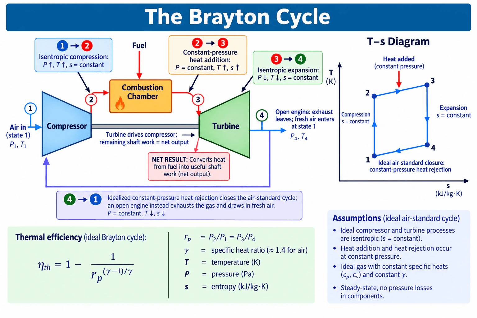
The Brayton cycle is the ideal cycle for a gas turbine. First, air is compressed isentropically, so its pressure and temperature rise while entropy stays constant. Second, heat is added at constant pressure. Third, the hot gas expands isentropically through the turbine, producing work while pressure and temperature fall. Finally, the ideal air-standard cycle rejects heat at constant pressure to return to the initial state. In a real open engine, the exhaust leaves and fresh air enters instead. In the simplified shaft arrangement, the turbine drives the compressor, and the remaining work is the net useful output.

Detailed Explanation

The Brayton cycle is a steady-flow gas-power cycle used as the ideal model for gas-turbine engines. A convenient control-volume boundary includes the compressor, heat-addition or combustion section, turbine, and the idealized heat-rejection process used to close the air-standard cycle. For the ideal model, assume steady state, an ideal gas with constant specific heats, negligible changes in kinetic and potential energy, no component pressure losses, and isentropic compressor and turbine processes. Take turbine work delivered by the gas as positive output and compressor work as a positive input magnitude, so the net specific work is w_net = w_turbine - w_compressor.

The four ideal processes are:

  1. State 1 → 2: Isentropic compression. The compressor raises pressure and temperature. Entropy remains constant, so P increases, T increases, and s is constant. Compressor work is supplied to the gas.
  1. State 2 → 3: Constant-pressure heat addition. Heat is added to the compressed gas, raising its temperature and entropy while pressure remains constant. In a practical gas turbine this is associated with combustion.
  1. State 3 → 4: Isentropic expansion. The hot gas expands through the turbine and produces work. Pressure and temperature decrease while entropy remains constant.
  1. State 4 → 1: Constant-pressure heat rejection in the ideal air-standard cycle. Temperature and entropy decrease at constant pressure so the ideal cycle returns to its starting state. A real open gas turbine does not physically recirculate the same working fluid through this step; instead, exhaust gas leaves the engine and fresh air enters at the compressor inlet.

For the simplified arrangement, the turbine and compressor share a shaft. Part of the turbine work drives the compressor, and the difference is the net shaft work:

w_net = w_turbine - w_compressor.

For an ideal Brayton cycle with constant specific heats, the thermal efficiency is:

η_th = 1 - 1 / r_p^((γ - 1)/γ)

where η_th is thermal efficiency, r_p is the compressor pressure ratio, r_p = P₂/P₁ = P₃/P₄ for the ideal cycle with no pressure losses, and γ = c_p/c_v is the specific-heat ratio. For air under the simple constant-property approximation, γ is commonly taken as approximately 1.4. Absolute temperature in kelvin is used in thermodynamic temperature relations.

A useful physical check is that the ideal T–s diagram has vertical 1 → 2 and 3 → 4 lines because both processes are isentropic. The 2 → 3 path moves toward higher temperature and entropy during constant-pressure heat addition, while 4 → 1 moves toward lower temperature and entropy during idealized constant-pressure heat rejection. Energy conservation also requires the net work output to equal the heat added minus the heat rejected for the complete ideal cycle.

Useful Questions to Ask the Interviewer
  • Are you asking for the ideal air-standard Brayton cycle or the behavior of a real gas-turbine engine?
  • Should I include the thermal-efficiency relation and assumptions, or only describe the four processes?
  • Should component losses such as non-isentropic compression, turbine inefficiency, pressure drop, or heat loss be considered?
Describe the Brayton cycle. diagram
How to Explain It in an Interview

Start with the four processes in order: compress the air, add heat at constant pressure, expand the hot gas through the turbine, and close the ideal cycle with constant-pressure heat rejection. State that the compressor and turbine are ideally isentropic, so entropy remains constant during processes 1 → 2 and 3 → 4. Then explain the energy balance: the turbine produces work, some of that work drives the compressor, and the remainder is net output in the simplified shaft-power representation. Finally, distinguish the ideal closed thermodynamic representation from an actual open gas turbine, where exhaust leaves and fresh air enters. This shows that you understand both the thermodynamic model and the physical machine.

Technical Approach
  1. Define the ideal air-standard Brayton-cycle control volume and assume steady-state operation.
  2. State the work sign convention: treat turbine work as positive output and compressor work as a positive input magnitude.
  3. Identify state 1 at the compressor inlet, state 2 at the compressor exit, state 3 at the turbine inlet after heat addition, and state 4 at the turbine exit.
  4. Model 1 → 2 as isentropic compression: P and T rise while s remains constant.
  5. Model 2 → 3 as constant-pressure heat addition: T and s rise.
  6. Model 3 → 4 as isentropic turbine expansion: P and T fall while s remains constant.
  7. Model 4 → 1 as ideal constant-pressure heat rejection, while noting that a real open engine instead exhausts the gas and takes in fresh air.
  8. Apply the steady-flow first-law energy balance to the compressor and turbine and calculate net work as turbine work minus compressor work when numerical data are provided.
  9. For constant-specific-heat ideal analysis, relate efficiency to pressure ratio using η_th = 1 - 1/r_p^((γ-1)/γ).
  10. Check that pressure levels, temperature changes, entropy behavior, T–s path directions, and the overall energy balance are physically consistent.
Practical Insights

The ideal Brayton model is simple because it assumes no pressure losses, constant specific heats, and perfectly isentropic compression and expansion. Real engines are more complicated: compressors and turbines have efficiencies below 100%, combustors have pressure losses, properties vary with temperature, and heat losses may occur. Increasing pressure ratio increases ideal-cycle thermal efficiency under the stated assumptions, but real designs must also consider compressor work, turbine-inlet temperature limits, component efficiency, materials, cooling, pressure losses, and net power output.

Why Interviewers Ask This

Interviewers are checking whether you understand a basic gas-power cycle, can distinguish ideal thermodynamic assumptions from a real open gas-turbine engine, and can correctly relate pressure, temperature, entropy, heat transfer, and work through the compressor, combustor, and turbine.

Common interview mistakes

Common mistakes include saying that combustion occurs at constant volume instead of approximately constant pressure in a practical combustor, reversing the compressor and turbine temperature trends, drawing entropy changes during ideal isentropic compression or expansion, drawing the ideal 1 → 2 or 3 → 4 paths as nonvertical on a T–s diagram, treating the ideal 4 → 1 heat-rejection process as a physical cooler that must exist in every open gas turbine, forgetting that turbine work must first supply compressor work before net output is available in the simplified shaft arrangement, and using the ideal pressure-ratio efficiency equation without stating its ideal-gas and constant-specific-heat assumptions.

Interview tip

Describe the cycle in the order 1 → 2 → 3 → 4 → 1 and tie each process to one physical component or idealized step. A strong answer also distinguishes the ideal air-standard cycle from a real open gas turbine, states that the ideal compression and expansion lines are vertical on a T–s diagram because entropy is constant, and explains that net work is turbine work minus compressor work.

Interviewer may ask next
What assumptions are made in the ideal Brayton cycle, and how would you validate them for a real gas turbine?

The ideal model assumes steady-state flow, an ideal gas, constant specific heats for the simple efficiency relation, isentropic compressor and turbine processes, constant-pressure heat addition and rejection, negligible kinetic and potential energy changes, and no component pressure losses. For a real machine, I would compare measured compressor and turbine inlet and outlet pressures and temperatures, determine compressor and turbine isentropic efficiencies, quantify combustor pressure loss, account for temperature-dependent properties, and check the overall steady-flow energy balance. If those losses are significant, I would use actual component efficiencies and measured state properties instead of the ideal relations.

How does increasing compressor pressure ratio affect an ideal Brayton cycle?

For the ideal Brayton cycle with constant specific heats, thermal efficiency increases with compressor pressure ratio according to η_th = 1 - 1/r_p^((γ-1)/γ). However, a higher pressure ratio also changes compressor work and the temperature levels throughout the cycle. In a real engine, the preferred pressure ratio is therefore a tradeoff involving compressor and turbine efficiency, allowable turbine-inlet temperature, cooling requirements, pressure losses, materials, and the desired net power output rather than efficiency alone.

3. How would you cool off an object or thermally insulate it?NEWThermodynamics And Heat TransferMediumHoneywell

Short Interview Answer (30-60 seconds)

I would start by defining the object, surrounding conditions, allowable temperature, heat generation, and whether the problem is transient or steady state. For cooling, I would reduce thermal resistance from the object to a colder sink by improving conduction, convection, radiation, or using a heat exchanger or refrigeration system if passive cooling is insufficient. For insulation, I would increase thermal resistance using low-conductivity materials, trapped gas layers, radiation barriers, and by minimizing thermal bridges and air leakage. I would then use an energy balance and thermal-resistance model to size the approach and validate it with temperature measurements under representative operating conditions.

Detailed Explanation

The basic idea is that cooling and insulation are opposite thermal-management objectives. Cooling means creating an effective path for heat to leave the object. Insulation means making it difficult for heat to cross the boundary between the object and its environment.

I would begin by defining the system boundary around the object and stating the operating conditions. Important inputs include the object's initial temperature, target temperature or allowable temperature range, ambient temperature, internal heat generation if any, exposed area, available cooling medium, allowable size and mass, environmental conditions, and required cooling time. I would also determine whether the problem is transient, where temperature changes with time, or steady state, where temperatures have stabilized.

For a transient object with negligible internal temperature gradients, a first energy balance can be written as

m c_p dT/dt = Q̇_in - Q̇_out,

where m is the object's mass in kg, c_p is specific heat in J/(kg·K), T is temperature in K or °C when only temperature differences are used, Q̇_in is the heat rate entering or generated in the object in W, and Q̇_out is the heat rate leaving in W. If internal gradients are important, I would use a spatial conduction model rather than treating the whole object as one uniform temperature.

For steady-state heat transfer, I would identify the main heat-transfer modes separately.

Conduction through a simple layer can be approximated by

Q̇_cond = k A ΔT / L,

where k is thermal conductivity in W/(m·K), A is area in m², ΔT is the temperature difference in K, and L is thickness in m.

Convection between a surface and a fluid can be written as

Q̇_conv = h A (T_s - T_∞),

where h is the convective heat-transfer coefficient in W/(m²·K), T_s is surface temperature, and T_∞ is the bulk fluid temperature. The value of h depends strongly on whether convection is natural or forced, the fluid, velocity, geometry, and flow regime, so I would use an appropriate correlation only within its valid range.

Radiation can be important at high temperatures or where convection is weak. A simplified surface-to-large-surroundings expression is

Q̇_rad = ε σ A (T_s^4 - T_sur^4),

where ε is emissivity, σ is the Stefan-Boltzmann constant, and T_s and T_sur must be absolute temperatures in kelvin. For more complex surface arrangements, I would also account for view factors and the radiative properties of the participating surfaces.

For cooling, I would look for the dominant thermal resistance and reduce it. If conduction from the object to a heat sink is limiting, I could increase contact area, use a more conductive path, reduce interface resistance, or improve contact pressure where mechanically appropriate. If convection is limiting, I could increase exposed area, add fins, increase airflow or liquid flow, or use a fluid with better heat-transfer characteristics. If the required temperature is below ambient, passive heat transfer to the ambient environment alone cannot continuously achieve that condition, so I would consider an active refrigeration or thermoelectric system with an appropriate heat-rejection path. If high transient heat loads are present, thermal mass or phase-change materials may help absorb energy temporarily, but the stored heat must eventually be rejected.

For insulation, I would increase the total thermal resistance. For a simple series path, the resistance concept is

R_cond = L/(kA)

and

R_conv = 1/(hA).

For thermal resistances in series carrying the same heat flow, I can add them to estimate

Q̇ = ΔT / R_total.

That immediately shows the main insulation strategies: increase thickness L, select a lower-conductivity material k, reduce unwanted convection, and reduce radiative exchange when radiation is significant. Practical insulation systems may use foam, fibrous insulation, trapped gas spaces, vacuum layers, or reflective barriers depending on temperature, pressure, moisture, structural, and manufacturing constraints.

I would also look carefully for thermal bridges. A highly conductive fastener, frame, support, pipe, or electrical feedthrough can bypass otherwise good insulation. Air leakage can also dominate the heat transfer if warm or cold air is allowed to move through gaps. Moisture matters because many insulation materials perform differently when wet, and condensation or freezing may introduce additional reliability concerns.

The engineering choice depends on the objective. If I need to cool an object quickly, I generally want a small thermal resistance to a sufficiently cold heat sink and enough heat-transfer area or flow capacity. If I need to keep an object near its current temperature, I generally want a large thermal resistance and low uncontrolled heat leakage. If there is continuous internal heat generation, insulation alone cannot prevent the object's temperature from eventually rising; at steady state, the generated energy must still leave the system through some heat-transfer path.

I would validate the selected approach by checking energy conservation, ensuring material and component temperature limits are not exceeded, and testing the object under representative ambient temperature, heat load, airflow, orientation, and operating duration. I would compare measured temperature-versus-time or steady-state temperatures with the thermal model. A significant mismatch would make me revisit assumptions such as contact resistance, convection coefficients, thermal properties, radiation, leakage, or unmodeled heat paths.

Useful Questions to Ask the Interviewer
  • Is the goal to cool the object below ambient temperature, or only keep it from overheating?
  • What is the object's initial temperature, target temperature, and maximum allowable temperature?
  • Is there continuous internal heat generation, and if so, approximately how much?
  • How quickly must the object cool, or how long must it remain within the required temperature range?
  • What are the ambient temperature, airflow, pressure, humidity, and orientation conditions?
  • Are there constraints on size, mass, power consumption, noise, cost, materials, or maintenance?
  • Are there surfaces or interfaces where thermal contact resistance or thermal bridging is likely to be important?
How to Explain It in an Interview

I would say that I first decide whether I am trying to move heat out of the object or block heat transfer into or out of it. Then I define the system boundary and determine whether the problem is transient or steady state. I identify conduction, convection, and radiation paths and build an energy balance or thermal-resistance network. For cooling, I reduce the dominant resistance to a colder heat sink by improving conduction, area, airflow, liquid flow, or active refrigeration if required. For insulation, I increase resistance using low-conductivity materials, trapped gas or vacuum layers, radiation barriers, and careful control of thermal bridges and leakage. Finally, I check energy conservation and physical limits and validate the design with temperature measurements under realistic operating conditions.

Technical Approach
  1. Define the thermal objective: cool the object, hold it near a target temperature, or reduce heat gain or loss.
  2. Define the system boundary, initial and ambient conditions, allowable temperatures, heat generation, geometry, and time requirement.
  3. Determine whether the problem is primarily transient or steady state.
  4. Identify all important heat-transfer paths: conduction, convection, radiation, contact interfaces, leakage, and any phase change.
  5. Write an energy balance with a clear sign convention.
  6. Build a thermal-resistance network where appropriate and identify the dominant resistance or heat leak.
  7. For cooling, reduce the limiting resistance or provide a colder heat sink; for insulation, increase the total resistance and eliminate thermal bridges or leakage.
  8. Check material temperature limits, operating conditions, energy conservation, and whether assumed correlations are valid.
  9. Evaluate tradeoffs such as size, mass, power, pressure drop, noise, cost, manufacturability, durability, and condensation risk.
  10. Validate with representative thermal testing and compare measured temperatures with the model.
Practical Insights

The main tradeoff is between heat-transfer performance and practical constraints. Stronger cooling may require more surface area, higher airflow or liquid flow, larger heat exchangers, more electrical power, greater pressure drop, more noise, or additional maintenance. Better insulation often requires more thickness, volume, mass, careful sealing, and management of thermal bridges and moisture. Material thermal properties can also change with temperature and environmental exposure. The simplest thermal-resistance model may be sufficient for early estimates, but complex geometry, strong radiation, temperature-dependent properties, fluid flow, or large internal temperature gradients may require more detailed analysis or simulation.

Why Interviewers Ask This

The interviewer is testing whether I can translate a broad thermal-management problem into a defensible engineering model. They want to see whether I distinguish transient from steady-state behavior, identify conduction, convection, and radiation correctly, define system boundaries and assumptions, use energy balances and thermal resistance concepts, recognize practical tradeoffs, and propose a way to validate the design rather than choosing a cooling or insulation method by intuition alone.

Common interview mistakes

Common mistakes include choosing a cooling or insulation material before defining the heat load and boundary conditions; ignoring whether the problem is transient or steady state; treating conduction, convection, and radiation as interchangeable; using an assumed convection coefficient without checking the flow regime; using Celsius instead of kelvin in the T^4 radiation equation; ignoring contact resistance, thermal bridges, air leakage, or moisture; assuming insulation can indefinitely control the temperature of an object with continuous internal heat generation; and accepting a simplified calculation without validating the actual temperature response.

Interview tip

Structure the answer around the heat path rather than immediately naming a material or cooling device. State the boundary conditions, distinguish transient from steady state, identify conduction, convection, and radiation, then explain whether you would increase or decrease the dominant thermal resistance. Mention validation and the physical limit that passive cooling cannot continuously cool an object below its available heat-sink temperature.

Interviewer may ask next
How would you verify that your cooling or insulation model is accurate?

I would instrument the object and relevant surroundings with appropriately placed temperature sensors and, if useful, measure heat input, flow rate, or electrical power. I would test under representative ambient temperature, airflow, orientation, heat load, and operating duration. For transient behavior, I would compare measured temperature-versus-time data with the predicted response. For steady state, I would compare equilibrium temperatures and energy flows. If the model and test disagree, I would investigate uncertain inputs such as convection coefficients, thermal conductivity, contact resistance, radiation, air leakage, sensor placement, or unmodeled heat paths before changing the design.

What changes if the object must be cooled below the ambient temperature?

A passive heat sink connected only to the ambient environment cannot continuously drive the object below ambient temperature because heat naturally flows from higher temperature to lower temperature. I would need access to a colder thermal reservoir or an active refrigeration method such as a vapor-compression system, chilled fluid loop, thermoelectric cooler, or another appropriate cooling technology. I would then include the heat removed from the object, required input work or electrical power, and heat rejected to the environment in the energy balance. For a refrigeration system, I would also evaluate coefficient of performance rather than thermal efficiency. I would check condensation, frost, insulation, sealing, and heat-rejection capacity because those become important when operating below ambient temperature.

4. What is Mach number and how is it significant?NEWFluid Mechanics And Fluid SystemsEasyHoneywell

Short Interview Answer (30-60 seconds)

Mach number is a dimensionless ratio defined as M = V/a, where V is the local flow velocity and a is the local speed of sound. It tells us how fast a fluid or object is moving relative to the speed at which small pressure disturbances travel through that fluid. Its main significance is identifying when compressibility effects associated with flow speed matter. At low Mach numbers, density changes caused by the motion may be small enough to use incompressible-flow models. As Mach number approaches 1, compressibility becomes important, and sonic or supersonic flow can involve choking, shock waves, and substantial changes in pressure, temperature, and density.

Detailed Explanation

Mach number gives a simple way to compare fluid velocity with the local speed of sound. It is defined as:

M = V/a

where M is Mach number, V is the local fluid or object velocity, and a is the local speed of sound in the fluid. Because both V and a have units of velocity, Mach number is dimensionless.

The physical importance of Mach number is that small pressure disturbances propagate through a fluid at the local speed of sound relative to the fluid. When the flow velocity is much smaller than that speed, density changes caused by the fluid motion are often small enough that an incompressible approximation is useful. As the flow velocity approaches the speed of sound, compressibility effects become increasingly important, and information carried by acoustic disturbances has a more limited ability to propagate upstream relative to the moving flow.

A common engineering classification is:

  • Subsonic: M < 1.
  • Sonic: M = 1.
  • Supersonic: M > 1.
  • Hypersonic: commonly used for very high supersonic Mach numbers, often around M >= 5, although this is an engineering convention rather than a fundamental physical discontinuity.

For many gas flows, an incompressible approximation is often reasonable when Mach number is below roughly 0.3 because density changes caused by flow acceleration are usually small. This is a practical guideline, not an absolute law. Large externally imposed pressure or temperature changes can still produce important density changes even at low Mach number, so the approximation must be checked against the actual problem and required accuracy.

For an ideal gas with approximately constant specific heats, the local speed of sound is commonly written as:

a = sqrt(gamma R T)

where gamma is the ratio of specific heats, R is the specific gas constant, and T is absolute temperature. This shows that Mach number depends not only on velocity but also on the thermodynamic state and properties of the fluid. The same physical velocity can therefore correspond to different Mach numbers at different temperatures or in different gases.

Mach number becomes especially important in nozzles, diffusers, turbines, compressors, aircraft flows, gas pipelines, and other high-speed gas systems. Near Mach 1, a flow can become choked at a controlling minimum-area section when the required pressure ratio is reached. Under fixed upstream stagnation conditions and fixed geometry, further lowering the downstream pressure then does not increase the mass flow rate through that choked section. Supersonic flows can also form shock waves, across which static pressure, temperature, density, and velocity change sharply while total pressure decreases because a shock is irreversible.

Useful Questions to Ask the Interviewer
  • Are we discussing an external aerodynamic flow or an internal flow such as a nozzle, duct, or pipe?
  • Should the gas be treated as ideal, and are temperature and gas properties known?
  • Is the goal simply to classify the flow regime, or to determine whether compressibility, choking, or shock effects must be included?
  • What accuracy is required before using an incompressible approximation?
How to Explain It in an Interview

I would first define Mach number as M = V/a and explain that it compares flow speed with the local speed of sound. Then I would connect that ratio to compressibility. At low Mach number, density changes caused by the flow motion are often small, so incompressible methods may be acceptable. As M approaches 1, compressibility becomes important. At sonic and supersonic conditions, phenomena such as choking and shock waves can occur, so compressible-flow equations are required. I would also point out that the speed of sound depends on temperature and fluid properties, so Mach number is a local flow quantity rather than simply another way of stating velocity.

To validate the choice of flow model, I would calculate Mach number using local velocity and local speed of sound, check the expected pressure, temperature, and density changes, and confirm whether density variation is small enough for the required engineering accuracy. If Mach number approaches unity, I would use compressible-flow relations and check specifically for sonic conditions, choking, and possible shock formation.

Technical Approach
  1. Identify the local fluid velocity V and the fluid state, especially absolute temperature when dealing with a gas.
  2. Determine the local speed of sound a using an appropriate fluid model and properties; for an ideal gas with approximately constant specific heats, a = sqrt(gamma R T).
  3. Calculate Mach number from M = V/a.
  4. Classify the flow as subsonic, sonic, or supersonic based on M.
  5. Decide whether density changes are negligible enough for an incompressible model; for many gas-flow problems, M < about 0.3 is a common initial guideline for motion-induced compressibility effects.
  6. If Mach number is significant, use compressible-flow relationships and evaluate phenomena such as choking or shock waves where relevant.
  7. Validate the model against expected pressure, temperature, and density changes and the accuracy required by the application.
Practical Insights

Mach number itself is simple to calculate, but the engineering model becomes more involved as Mach number increases. At low Mach number, an incompressible approximation can simplify analysis when density changes are small. At higher Mach number, pressure, temperature, density, and velocity become strongly coupled, so compressible-flow equations are needed. Near Mach 1, choking may limit mass flow, and in supersonic flow, shocks can create sharp changes in flow properties and irreversible losses in total pressure. The tradeoff is therefore between using a simpler model when density variation is negligible for the required accuracy and using a more complete compressible model when the flow physics require it.

Why Interviewers Ask This

Interviewers use this question to check whether the candidate understands the physical meaning of Mach number and can use it to decide when compressible-flow effects must be considered rather than applying incompressible-flow equations automatically.

Common interview mistakes

Common mistakes include treating Mach number as velocity rather than a velocity ratio, using a fixed speed of sound without considering temperature or fluid properties, assuming every subsonic flow is incompressible, assuming low Mach number automatically means density is constant under all pressure and temperature changes, using incompressible Bernoulli equations near Mach 1, and ignoring choking or shock waves in high-speed internal flows.

Interview tip

State the equation M = V/a immediately, then explain its physical meaning: it compares flow speed with the local speed of sound. Connect the answer to model selection by saying that low-Mach gas flow may often be treated as incompressible when density changes are small, while flow approaching Mach 1 requires compressible-flow analysis and may involve choking or shocks.

Interviewer may ask next
Why is Mach 0.3 often used as a guideline for deciding whether gas flow can be treated as incompressible?

For many gas-flow problems below about Mach 0.3, density changes caused by flow acceleration are small enough that an incompressible approximation gives acceptable engineering accuracy. It is a practical guideline rather than an exact physical boundary. Large imposed pressure or temperature changes can still produce important density variation at low Mach number, so the approximation should be checked against the actual operating conditions and required accuracy.

What changes when the flow reaches Mach 1 in a nozzle?

At Mach 1, the local flow velocity equals the local speed of sound. In a converging nozzle carrying compressible gas, this condition can occur at the minimum-area section when the pressure ratio is sufficient to choke the flow. Once choked, reducing downstream pressure further does not increase mass flow through that section when upstream stagnation conditions and geometry remain fixed. To accelerate a one-dimensional, isentropic flow from sonic to supersonic conditions, the passage must expand downstream of the sonic throat, as in a converging-diverging nozzle.

5. How do steady and unsteady flow differ?NEWFluid Mechanics And Fluid SystemsEasyHoneywell

Short Interview Answer (30-60 seconds)

In steady flow, the relevant fluid properties at any fixed point do not change with time. Mathematically, for velocity V, a steady flow has ∂V/∂t = 0 at a fixed location, with the same time-independence applying to other relevant properties such as pressure or density. In unsteady flow, at least one relevant property changes with time. Steady flow can still vary from place to place, so it should not be confused with uniform flow. A piping system at a stable operating condition may be approximately steady, while pump startup or valve movement produces unsteady flow.

Detailed Explanation

Steady and unsteady flow are distinguished by whether fluid properties change with time at a fixed spatial location.

For steady flow, the relevant Eulerian properties, such as velocity, pressure, density, and mass flow rate, remain constant with time at each fixed point in the flow field. If velocity is represented by V, the steady condition is ∂V/∂t = 0 at a fixed location. Corresponding time derivatives of the other relevant flow properties are also zero when those properties are steady.

For unsteady flow, at least one relevant property changes with time at a fixed location, so a time derivative such as ∂V/∂t is not zero.

Steady does not mean uniform. Uniform flow refers to a lack of spatial variation, while steady flow refers to a lack of time variation. For example, consider incompressible water flowing continuously through a pipe that narrows. For one-dimensional steady incompressible flow, continuity gives A₁V₁ = A₂V₂. The velocity is therefore higher in the smaller-area section, so velocity varies with position even though the velocity at each fixed location can remain constant with time. The flow can therefore be steady but nonuniform.

A common unsteady example is pump startup. Immediately after the pump starts, flow rate and pressure may change until the system approaches a stable operating point. Opening or closing a valve can also produce transient changes in velocity and pressure. If the change is sufficiently rapid, pressure waves and effects such as water hammer may become important.

Whether a real flow can be treated as steady is an engineering modeling decision. The relevant question is whether temporal variations are negligible relative to the accuracy and time scale required by the analysis. If a steady approximation is justified, the applicable mass, momentum, or mechanical-energy equations can be used under their stated assumptions. Compressibility, elevation change, major losses, and minor losses should still be included when they are relevant; steady flow does not imply ideal or lossless flow.

Useful Questions to Ask the Interviewer
  • Are we defining steady behavior at a fixed location in the flow field? This confirms that the distinction is based on variation with time rather than variation with position.
  • Should the fluid be treated as incompressible? For a basic liquid-flow example that may be reasonable, but it should not be assumed for every system.
  • Are we considering normal operation or a transient event such as startup, shutdown, or valve movement? Normal operation may often be approximated as steady, while those transient events are inherently unsteady.
How to Explain It in an Interview

I would first state the time-based definition: steady flow has no change in the relevant fluid properties with time at a fixed location, while unsteady flow has time-dependent properties. I would then clarify that steady is different from uniform. A converging pipe can have different velocities at different positions and still be steady if the velocity at each position remains constant with time. Finally, I would give a practical contrast: a piping system operating at a stable pump-system operating point can often be approximated as steady, while startup, shutdown, or valve movement requires transient analysis. The steady-flow assumption should be validated by checking whether the actual temporal variation is negligible for the engineering decision being made.

Technical Approach
  1. Define the fluid system and the fixed location or control volume being observed.
  2. Identify the relevant properties, such as velocity, pressure, density, and mass flow rate.
  3. Check whether those properties change with time at fixed spatial locations.
  4. If the relevant time derivatives are zero, or negligibly small for the required engineering accuracy, treat the flow as steady.
  5. If one or more relevant properties change materially with time, treat the flow as unsteady.
  6. Separately check for spatial variation so that steady flow is not incorrectly assumed to be uniform flow.
  7. Validate the assumption against the actual operating condition, especially during startup, shutdown, valve movement, or other transient events.
Practical Insights

A steady-flow model is usually simpler because time does not have to be tracked explicitly, so conservation equations can often be evaluated at a fixed operating condition. An unsteady-flow model must capture how properties such as pressure, velocity, density, or flow rate evolve with time, which can require transient measurements or numerical time stepping. The tradeoff is simplicity versus fidelity: a steady approximation is efficient when temporal changes are negligible, but it can miss important transient effects such as pressure surges.

Why Interviewers Ask This

Interviewers use this question to check whether the candidate can distinguish time variation from spatial variation in a fluid system. That judgment determines whether a steady-state model is appropriate or whether time-dependent conservation equations and transient system behavior must be considered.

Common interview mistakes

A common mistake is saying that steady flow means velocity is the same everywhere. That describes spatial uniformity, not steadiness. Another mistake is checking only velocity while ignoring time changes in pressure, density, or flow rate that may make the overall flow unsteady. Candidates may also treat startup or rapid valve movement as steady-state conditions even though those are transient events.

Interview tip

Lead with the fixed-location definition and then immediately distinguish steady from uniform flow. A strong example is a narrowing pipe: velocity can change with position while remaining constant with time at each location, so the flow can be steady but nonuniform.

Interviewer may ask next
How would you determine whether a real flow can reasonably be treated as steady?

I would monitor the relevant variables, such as pressure, velocity, density, or flow rate, over the time interval important to the analysis. If their temporal variations are negligible compared with the accuracy required for the engineering decision, a steady approximation may be justified. I would also check whether the system is undergoing startup, shutdown, valve movement, pulsation, or another known transient. The assumption should be validated using measurements, operating data, or an appropriate transient model when needed.

Can a flow be steady but nonuniform?

Yes. Steady means properties at a fixed location do not change with time, while nonuniform means properties vary from one location to another. For example, incompressible flow through a converging pipe can be steady while velocity increases as cross-sectional area decreases. At each fixed location the velocity can remain constant with time even though different locations have different velocities.

6. Why is it important to have pressure relief valves?NEWSafetyEasyHoneywell

Short Interview Answer (30-60 seconds)

Pressure relief valves are important because they provide a controlled way to release pressure before a vessel, pipe, or other pressurized component is subjected to an unsafe overpressure condition. If pressure keeps increasing, the stored energy can cause leaks, rupture, equipment damage, or serious injury. A properly selected and maintained relief valve acts as an engineering control: it opens at a specified set pressure and provides enough relieving capacity to limit pressure according to the applicable design requirements. It does not replace good process control, inspection, or safe operating procedures, but it provides an independent layer of protection against overpressure.

Detailed Explanation

Pressure relief valves protect pressurized systems from dangerous overpressure. A closed pressure system stores energy, and if pressure rises beyond what the pressure boundary is designed to tolerate, that energy may be released suddenly through a leak or rupture. A relief valve provides a designed pressure-release path so pressure can be limited during an abnormal condition.

The basic idea is that the valve remains closed during normal operation. If the protected system reaches the valve's specified set pressure, the valve begins to open and allows fluid to leave the protected volume. It must provide sufficient relieving capacity for the applicable overpressure scenario so the system pressure remains within the limits permitted by the governing design basis. After pressure falls sufficiently, many spring-loaded relief valves are designed to reseat, although exact opening and closing behavior depends on the relief-device type and application.

This is important because overpressure can come from several causes, such as blocked discharge, thermal expansion of trapped liquid, control-system failure, external heating, equipment malfunction, or an upstream pressure source. The exact credible scenarios depend on the equipment and process, so I would identify them through a risk assessment rather than assume a single cause.

A pressure relief valve is an engineering control in the hierarchy of controls. It is generally more reliable than depending only on procedures or personal protective equipment because it acts directly on the hazardous pressure condition. However, it is not sufficient by itself. The complete protection strategy can also include appropriate system design, pressure control, isolation procedures, inspection, maintenance, and management of changes that could affect the relief path or required capacity.

For a real design, I would not choose a relief valve simply from the normal operating pressure. I would first define the protected equipment, its applicable pressure limits, fluid, operating temperature, credible overpressure cases, required relieving capacity, discharge destination, and applicable jurisdiction and equipment requirements. I would also verify that the inlet and outlet piping do not create unacceptable pressure losses or backpressure and that the discharge does not create a new hazard such as exposing personnel to hot, toxic, flammable, or high-velocity fluid.

Validation is also essential. Before operation, the engineer should confirm that the installed valve matches the design basis, the set pressure and capacity are appropriate for the protected system, any isolation valves are in the required operating position, the discharge route is unobstructed, and applicable inspection or test requirements are satisfied. During maintenance, stored pressure must be identified, isolated, released, and verified according to the authorized procedure before work begins.

The main limitation is that a relief valve controls the consequence of an overpressure event but does not remove the initiating cause. If a relief valve opens, the cause still needs to be understood and corrected. Repeated lifting should not be treated as normal operation because it may indicate an unresolved process, control, equipment, or sizing problem.

Useful Questions to Ask the Interviewer
  • What type of pressurized equipment is being protected, such as a vessel, piping section, heat exchanger, compressor system, or hydraulic circuit?
  • What are the normal operating pressure and temperature, and what pressure limits apply to the protected equipment?
  • What credible overpressure scenarios must be considered?
  • What fluid could be released, and where is the relief discharge routed?
  • Are there applicable jurisdictional, equipment, or site requirements that govern the relief-device design and inspection?
How to Explain It in an Interview

I would explain that a pressure relief valve is an engineering control for overpressure. I would first identify the protected pressure boundary and the credible causes of excessive pressure. Then I would verify the applicable equipment pressure limits, determine the relieving requirement for the governing scenario, select an appropriate relief device and discharge path, and check installation factors such as inlet pressure loss and backpressure. Finally, I would verify the installed configuration, inspection status, and safe maintenance controls. The key point is that the valve gives stored pressure a controlled escape path and limits pressure during abnormal conditions, but it must be correctly selected, installed, maintained, and supported by other risk controls.

Technical Approach
  1. Define the protected pressure boundary and its applicable pressure limits.
  2. Identify credible overpressure scenarios using a risk assessment or failure analysis.
  3. Determine the fluid state, operating conditions, and required relieving capacity for the governing scenario.
  4. Select an appropriate pressure relief device with a suitable set pressure and capacity under the applicable equipment and jurisdiction requirements.
  5. Design the inlet and discharge path so pressure losses, backpressure, temperature, phase change, reaction forces, and release hazards are appropriately addressed.
  6. Verify the installed device, isolation-valve configuration, discharge routing, identification, and inspection or test status before operation.
  7. During maintenance, isolate, release, and verify stored pressure according to the authorized procedure before work.
  8. Investigate any relief event and correct the initiating cause rather than treating repeated lifting as normal.
Practical Insights

The main tradeoff is providing reliable overpressure protection without causing unnecessary releases or process interruptions. The relief device has to be coordinated with normal operating pressure and the protected equipment's permitted pressure limits. It also needs enough relieving capacity for each applicable credible scenario rather than being selected from unsupported assumptions. The discharge system must safely handle the released fluid; otherwise the relief device can transfer the hazard from overpressure to personnel exposure, fire, environmental release, excessive backpressure, or reaction loads.

Why Interviewers Ask This

Interviewers want to see whether I understand overpressure as a serious stored-energy hazard and recognize a pressure relief valve as an engineering control that protects people, equipment, and the pressure boundary when normal pressure control fails or an abnormal condition causes pressure to rise.

Common interview mistakes

Common mistakes include assuming normal pressure control makes a relief valve unnecessary, selecting a valve only from normal operating pressure, ignoring credible cases such as blocked flow or thermal expansion, allowing an isolation configuration that can unintentionally block the relief path, overlooking inlet pressure loss or discharge backpressure, routing the discharge where it creates a new hazard, bypassing or disabling the device, and treating repeated relief events as acceptable instead of investigating the cause.

Interview tip

Keep the answer centered on stored-energy risk and engineering controls. A strong response is: identify the overpressure hazard, explain that the relief valve provides a controlled pressure-release path, mention that it must be correctly set, sized, installed, and discharged safely, and finish by saying it complements rather than replaces normal controls, inspection, and safe maintenance practices.

Interviewer may ask next
How would you verify that a pressure relief valve can actually protect the equipment?

I would first verify the protected equipment's applicable pressure limits and the relief valve's specified set pressure. Then I would identify the credible overpressure scenarios and determine the required relieving capacity for the governing case. I would confirm that the selected valve provides adequate capacity at the relevant fluid and operating conditions and check the inlet and outlet piping for pressure loss, backpressure, blockage, and safe discharge routing. Finally, I would verify the actual installed device, isolation-valve configuration, inspection or test status, and applicable equipment or jurisdiction requirements. A calculation alone is not enough; the installed system has to match the design basis.

What changes if the relieved fluid is hot, toxic, or flammable?

The pressure-protection purpose stays the same, but the discharge system becomes a major part of the hazard assessment. I would avoid releasing the fluid where personnel could be exposed and evaluate temperature, toxicity, flammability, phase change, dispersion, ignition sources, reaction forces, and backpressure. Depending on the application, the discharge may need to go to a closed recovery, treatment, flare, scrubber, or another engineered system rather than directly to the surrounding area. The final arrangement must follow the applicable requirements for that specific equipment, fluid, service, and jurisdiction.

7. When is a compressible flow model considered?NEWSimulation And Engineering AnalysisMediumHoneywell

Short Interview Answer (30-60 seconds)

I consider a compressible flow model when density changes can materially affect the result. For gases, I first check Mach number, Ma = V/a. Around Ma ≥ 0.3, compressibility effects often become important, but Mach number is only a screening criterion. I would also use compressible physics for large pressure or temperature changes and for phenomena such as choking, shocks, strong expansion, or pressure-wave propagation. I would confirm the choice by estimating the expected density variation and checking whether an incompressible model could still meet the required engineering accuracy.

Detailed Explanation

A compressible flow model is needed when fluid density cannot reasonably be treated as constant throughout the flow. The decision should come from the physics that matter to the engineering question rather than simply selecting a more complicated CFD model.

For a gas, an important first check is the Mach number:

Ma = V/a

where Ma is Mach number, V is the local flow velocity, and a is the local speed of sound. As a practical engineering screening rule, compressibility effects often become important around Ma ≥ 0.3 because changes in pressure associated with the flow can then produce noticeable density changes. This threshold is not an absolute boundary. A lower-Mach gas flow can still require a variable-density model if pressure or temperature changes are large.

I would also consider compressible modeling when the system includes strong gas expansion or compression, high pressure ratios, converging-diverging passages, possible choking, shock waves, acoustic or pressure-wave propagation, or strong coupling between temperature and density. In these cases, pressure, temperature, density, and velocity are coupled through conservation laws and an equation of state, so assuming constant density can distort mass flow, pressure distribution, or other quantities of interest.

For liquids, an incompressible model is appropriate for many ordinary steady flows because their density changes are small. However, liquid compressibility can matter in rapid transients such as water hammer or other pressure-wave problems. If phase change such as cavitation is possible, I would also evaluate whether a multiphase or cavitation model is required rather than assuming that a single-phase compressible model alone describes the physics.

Useful Questions to Ask the Interviewer
  • What fluid and operating pressure range are expected?
  • What velocity or Mach-number range is expected?
  • What temperature range should the model cover?
  • Are choking, shocks, strong expansion, or transient pressure waves possible?
  • Is phase change such as cavitation relevant?
  • Which output drives the engineering decision, such as mass flow, pressure loss, temperature, force, or transient peak pressure, and what accuracy is required?
How to Explain It in an Interview

I would say that I begin with the simplest model that preserves the important physics. First, I estimate Mach number and the expected changes in pressure and temperature. I then estimate whether those conditions produce a meaningful density change. If density variation is negligible relative to the accuracy required, an incompressible model can be justified. If density changes materially affect continuity, momentum, energy, or the quantity of interest, I use a compressible formulation with suitable thermodynamic properties or an equation of state.

After choosing the model, I would verify that the numerical solution is credible by checking mass and energy conservation where applicable, residual behavior, mesh convergence, boundary-condition sensitivity, and consistency with a hand calculation or limiting case. If test data are available, I would use them for validation. Solver convergence by itself would not prove that the chosen physical model is correct.

The main limitation of the Ma ≈ 0.3 guideline is that it mainly screens velocity-driven gas compressibility. Large thermal or pressure-induced density variations can make compressibility important even below that value. Therefore, the final decision is based on expected density variation and the engineering accuracy required.

Technical Approach
  1. Define the fluid, operating pressure, temperature range, velocity range, geometry, and quantity of interest.
  2. For gas flow, estimate the local Mach number using Ma = V/a.
  3. Estimate pressure- and temperature-driven density changes using an appropriate thermodynamic relation or property model.
  4. Determine whether those density changes are significant relative to the required engineering accuracy.
  5. Identify additional compressible phenomena such as choking, shocks, strong expansion, or pressure-wave propagation.
  6. Select incompressible, variable-density, compressible, or additional multiphase physics according to the phenomena that must be represented.
  7. Apply physically justified inlet, outlet, wall, thermal, and initial conditions.
  8. Verify numerical credibility through conservation checks, residual behavior, mesh convergence, and sensitivity studies.
  9. Compare against a hand calculation, limiting case, or established analytical result where possible.
  10. Validate against experimental evidence when the analysis will support a real engineering decision.
Practical Insights

An incompressible model is usually simpler and can require less computational effort because density is treated as essentially constant. A compressible model adds coupling among pressure, density, temperature, velocity, and often the energy equation, so it can require more careful boundary conditions, property data, mesh resolution, and solver control. The tradeoff is model fidelity versus computational cost. Using compressible physics when it is unnecessary can add complexity, while using an incompressible model when density changes are important can produce incorrect mass-flow, pressure, temperature, or transient predictions.

Why Interviewers Ask This

The interviewer is evaluating whether the candidate can choose appropriate CFD physics instead of automatically using an incompressible model. The key judgment is recognizing when variations in pressure, temperature, velocity, and density are sufficiently coupled that density must remain a solved thermodynamic variable.

Common interview mistakes

A common mistake is treating Ma = 0.3 as an absolute rule instead of a screening guideline. Another is checking velocity but ignoring large pressure or temperature changes that can also change gas density. Candidates may also confuse compressible flow with turbulence; they are separate modeling decisions. In CFD, another mistake is selecting a compressible solver without using appropriate thermodynamic properties, energy modeling, or physically consistent boundary conditions. Finally, numerical convergence should not be mistaken for physical validation.

Interview tip

Lead with the physical criterion: use a compressible model when density changes materially affect the result. Then mention Ma ≈ 0.3 as a practical gas-flow screening guideline, followed by the important exceptions such as large pressure or temperature changes, choking, shocks, and pressure waves. This shows that you understand both the rule of thumb and its limitations.

Interviewer may ask next
How would you verify that an incompressible assumption is acceptable for a gas-flow simulation?

I would estimate the maximum Mach number and the expected density variation over the operating pressure and temperature range. I would then compare that variation with the accuracy required for the quantity of interest. For a borderline case, I could compare an incompressible or constant-density solution with a variable-density or compressible solution using consistent boundary conditions and an adequately converged mesh. I would check mass conservation and key outputs such as mass flow, pressure loss, and temperature. If the differences are negligible for the engineering decision, the simpler assumption is justified.

What changes if the flow reaches sonic conditions in a nozzle?

If the local Mach number reaches 1, compressible effects are essential. The flow can become choked, meaning the mass flow is constrained by the sonic condition at the controlling section and cannot be predicted correctly with a constant-density incompressible model. Pressure, temperature, density, and velocity must be coupled consistently. Depending on the downstream pressure and nozzle geometry, further expansion and shock waves may also occur, so I would use a compressible formulation with suitable thermodynamic properties and verify that the mesh and boundary conditions can resolve the expected flow features.

8. What did you learn in your previous roles?NEWBehavioralEasyHoneywell

Question Details

Discuss the learning you took from those roles.

Interview tip:

Use STAR to structure your answer: briefly explain the Situation and Task, make Action the most detailed part, and finish with the Result. For example, describe a previous engineering role where you learned to connect technical analysis with practical manufacturing limits, communicate clearly with other teams, verify assumptions before making design decisions, and apply those lessons to improve later work.

Situation

In my last role, I worked on a mechanical component that needed a design update because the existing version was difficult to manufacture consistently. The engineering analysis looked acceptable, but feedback from manufacturing showed that some dimensions and assembly steps were creating unnecessary variation.

Task

I was responsible for reviewing the design, understanding the manufacturing concerns, and recommending changes that would keep the component functional while making it easier to produce and inspect.

Action

I first reviewed the drawings, design requirements, and the assumptions behind the original analysis. I then spoke with manufacturing and quality team members to understand where the real problems occurred during fabrication and inspection. That taught me that a design can be technically correct but still cause problems if manufacturing limits are not considered early. I compared possible design changes and checked how each option could affect strength, fit, assembly, and inspection. Before recommending a change, I verified the important assumptions instead of relying only on the previous design. I also documented the reason for each change so other team members could review the decision clearly. Through that work, I learned to involve manufacturing and quality earlier, communicate technical decisions in simple terms, and treat feedback from other functions as important engineering input rather than as a final review step.

Result

The updated design was easier for the team to manufacture and inspect while still meeting the required function. More importantly, I carried those lessons into later work. I became more careful about checking assumptions, considering the full product life cycle, and involving the right people before a design became difficult to change.

Why Interviewers Ask This

Interviewers ask this question to understand whether a candidate reflects on past experience and turns it into better professional judgment. A strong answer shows that the candidate can learn from technical work, collaboration, feedback, and previous decisions and then apply those lessons in future engineering situations.

Interviewer may ask next
Which lesson from that experience has changed the way you approach new designs the most?

The biggest lesson was to involve manufacturing and quality earlier. I now try to understand practical production and inspection limits while the design is still flexible. That helps me identify issues sooner and make better design decisions before changes become expensive or difficult.

What would you do differently if you faced the same situation today?

I would bring the manufacturing and quality teams into the discussion at the beginning instead of waiting until the design review stage. I would also confirm the most important assumptions earlier and document key decisions as the design develops. That would make the process more efficient and reduce avoidable rework.

9. What are you weakest at when communicating?NEWBehavioralEasyHoneywell

Question Details

Focus on weaknesses in your communication.

Interview tip:

Use STAR to structure your answer: briefly explain the Situation and Task, make Action the most detailed part, and finish with the Result. For example, describe a time when you realized that you were giving too much technical detail, how you adjusted your message for different audiences, how you checked understanding, and what you learned about communicating more clearly.

Situation

In my last role, I noticed that one of my communication weaknesses was giving too much technical detail when explaining engineering work. During a design review, I explained a mechanical issue using detailed analysis and engineering terms, even though some people in the meeting mainly needed to understand the decision, the risk, and the next step.

Task

I needed to make sure everyone understood why I was recommending a design change. I also realized that I needed to improve how I adjusted my communication for people with different technical backgrounds.

Action

I changed how I prepared for discussions like that. Before a meeting, I started identifying what each audience needed to know. I would first explain the problem in simple terms, then describe the impact on performance, reliability, schedule, or safety as appropriate. I kept the deeper calculations and technical details available for anyone who wanted them instead of leading with them. I also started pausing after important points and asking whether the explanation was clear or whether more detail would help. When I used drawings or analysis results, I explained what the audience should notice instead of assuming the data spoke for itself. I also asked teammates for feedback after a few reviews so I could see where my explanations were still too detailed.

Result

My communication became clearer, and discussions were easier because people could understand the main engineering decision before going into the supporting details. I learned that strong technical communication is not about showing everything I know. It is about giving people the information they need in a form they can use. I still pay attention to this weakness because I naturally enjoy technical detail, but I now manage it much more deliberately.

Why Interviewers Ask This

Interviewers ask this question to see whether a candidate can recognize a real communication weakness, take responsibility for improving it, and show practical self awareness. A strong answer demonstrates that the candidate can adjust technical information for different audiences while still communicating engineering decisions accurately.

Interviewer may ask next
How do you decide how much technical detail to include when speaking with different audiences?

I start by thinking about the decision the audience needs to make and what information they need to make it. For engineers, I may include assumptions, calculations, and design constraints. For a broader group, I usually begin with the problem, the impact, the recommendation, and the main reason behind it. I keep the supporting technical detail ready so I can go deeper when someone needs it.

What would you do differently if you noticed that people were still confused during a technical discussion?

I would stop and change the way I was explaining the issue instead of repeating the same explanation. I might use a simple sketch, compare the options more directly, or explain the practical effect before returning to the technical reason. I would also ask a specific question to check what part was unclear. That helps me address the actual gap in understanding rather than adding more information.

10. When was a time you faced criticism?NEWBehavioralMediumHoneywell

Question Details

How did you deal with it?

Interview tip:

Use STAR to structure your answer: briefly explain the Situation and Task, make Action the most detailed part, and finish with the Result. For example, describe a time you received criticism about an engineering design, listened carefully, clarified the concern, reviewed the technical reasoning, improved your work, and used the feedback to become a better engineer.

Situation

During a previous project, I prepared a mechanical component design and presented it during a design review. A senior engineer criticized parts of my drawing because some tolerances were tighter than the manufacturing process needed and my reasoning was not clearly documented. I had spent significant time on the design, so the feedback was difficult to hear at first.

Task

I was responsible for making sure the design was functional, practical to manufacture, and clearly communicated through the engineering drawing. I needed to understand the criticism, determine whether the concerns were valid, and improve the design without becoming defensive.

Action

I listened to the full feedback before responding and wrote down each concern. I asked the senior engineer to explain which tolerances created the greatest manufacturing risk and why. I then reviewed the functional requirements for each critical dimension and checked how variation in those dimensions could affect fit and performance. I realized that I had selected some tolerances mainly because they seemed conservative, rather than because the function required them. I revised those dimensions using tolerances that still protected the design intent but were more practical for manufacturing. I also added clearer notes showing why the important dimensions mattered. Before the next review, I discussed the revised drawing with a manufacturing engineer to confirm that the requirements were realistic. I then returned to the reviewer, explained what I had changed, and thanked them for pointing out the weakness in my original approach.

Result

The revised design was accepted and was easier for manufacturing to understand and produce. More importantly, I learned not to treat criticism of my work as criticism of me personally. Now I try to understand the technical reason behind feedback, verify it with evidence, and use it to improve both the current design and the way I approach future work.

Why Interviewers Ask This

Interviewers ask this question to understand how a candidate responds when their work is challenged. A strong answer shows that the candidate can listen without becoming defensive, evaluate feedback objectively, communicate professionally, take ownership, and turn criticism into better engineering decisions.

Interviewer may ask next
How did you keep yourself from becoming defensive during the design review?

I focused on separating the design from myself. Instead of trying to defend every decision immediately, I wrote down the concerns and asked questions so I could understand the technical reasoning. That gave me time to evaluate the feedback based on function and manufacturing needs rather than reacting emotionally.

What would you do differently if you faced a similar situation now?

I would involve manufacturing earlier and document the reason for each important tolerance before the formal review. That would help me identify unnecessary constraints sooner and make the design review more focused on the remaining technical risks.

More questions load as you scroll

Disclaimer: This interview guide is for educational and informational purposes only. It is designed to help readers prepare, but it does not guarantee any interview result, hiring decision, offer, or outcome. Interview questions, hiring criteria, and preferred answers can vary by employer, interviewer, industry, location, and time. All answers, examples, and explanations in this guide are suggested examples for interview preparation, not definitive answers or instructions for professional practice. They are based on research and judgment, are provided without warranties of any kind, and should be adapted to the question, role, and applicable laws and professional requirements. Diagrams are simplified illustrations intended to highlight the main concepts and their relationships; actual situations, systems, and practices may be more complex. Alternative approaches may be equally valid or better suited to a particular question, context, or interviewer. To the fullest extent permitted by applicable law, the contributors and publisher are not liable for decisions made, actions taken, or losses incurred based on this guide.

State Laws and Professional Responsibilities: Laws and requirements governing an occupation vary by state and jurisdiction. You are responsible for checking the current laws, licensing requirements, and scope-of-practice rules that apply to your location and role, and for ensuring that your answers and actions comply with them. Adapt examples in this guide to those requirements. This guide is not legal advice.

Company Notice: This guide is an independent educational resource and is not affiliated with, endorsed by, sponsored by, or approved by the company named in this guide. Company names identify reported interview experiences or the employer context of clearly labeled original practice exercises. Interview practices can change without notice, and inclusion of company-specific content does not mean these questions are official, complete, or guaranteed to be asked. To the fullest extent permitted by law, the author, contributors, and publisher are not responsible for outcomes related to use of this material.

Content Accuracy and Verification: To the fullest extent permitted by applicable law, we do not represent or warrant that interview guides, questions, answers, examples, or diagrams are accurate, complete, current, error-free, or suitable for any particular purpose. You are responsible for independently reviewing and verifying the information before relying on it.