48 top • 14 Boeing • 6 Bosch • 2 Caterpillar • 9 Ford • 6 GE Aerospace • 4 Honeywell • 8 John Deere • 3 Lockheed Martin • 3 Rolls-Royce • 2 Siemens Energy • 4 Tesla
Questions with Detailed ExplanationsWith Detailed Explanations
This interview guide is for educational and informational purposes only. It is designed to help readers prepare, but it does not guarantee any interview result, hiring decision, offer, or outcome. Interview questions, hiring criteria, and preferred answers can vary by employer, interviewer, industry, location, and time. All answers, examples, and explanations in this guide are suggested examples for interview preparation, not definitive answers or instructions for professional practice. They are based on research and judgment, are provided without warranties of any kind, and should be adapted to the question, role, and applicable laws and professional requirements. Diagrams are simplified illustrations intended to highlight the main concepts and their relationships; actual situations, systems, and practices may be more complex. Alternative approaches may be equally valid or better suited to a particular question, context, or interviewer. To the fullest extent permitted by applicable law, the contributors and publisher are not liable for decisions made, actions taken, or losses incurred based on this guide.
State Laws and Professional Responsibilities
Laws and requirements governing an occupation vary by state and jurisdiction. You are responsible for checking the current laws, licensing requirements, and scope-of-practice rules that apply to your location and role, and for ensuring that your answers and actions comply with them. Adapt examples in this guide to those requirements. This guide is not legal advice.
Identity, Image, and Privacy Notice
To respect individual privacy, some names, profile photographs, avatars, biographical details, and other identifying information displayed in this guide may be replaced with pseudonyms, licensed stock images, illustrative avatars, composite images, or representative descriptions. Unless a person is expressly identified as an actual contributor, a displayed name, image, or profile should not be understood as depicting or identifying a specific candidate, interviewer, employee, or other real individual. These representations are provided for editorial and illustrative purposes only and do not imply endorsement, employment, participation, or affiliation with this guide or any company mentioned in it. Any resemblance to an actual person is coincidental.
Company Notice
This guide is an independent educational resource and is not affiliated with, endorsed by, sponsored by, or approved by the company named in this guide. Company names identify reported interview experiences or the employer context of clearly labeled original practice exercises. Interview practices can change without notice, and inclusion of company-specific content does not mean these questions are official, complete, or guaranteed to be asked. To the fullest extent permitted by law, the author, contributors, and publisher are not responsible for outcomes related to use of this material.
Content Accuracy and Verification
To the fullest extent permitted by applicable law, we do not represent or warrant that interview guides, questions, answers, examples, or diagrams are accurate, complete, current, error-free, or suitable for any particular purpose. You are responsible for independently reviewing and verifying the information before relying on it.
Questions or comments?
Contact us for general questions, or share feedback, technical corrections, and comments with the community.
1. What is a load path in a mechanical assembly?Engineering MechanicsEasy
Short Interview Answer (30-60 seconds)
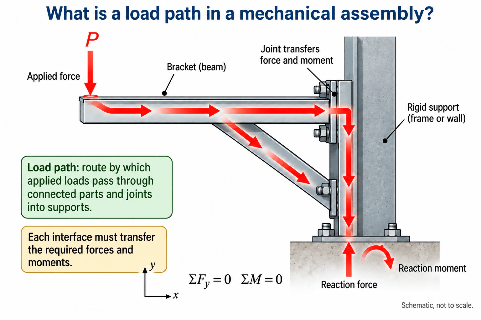
A load path is the route by which an applied load is transferred through connected parts and joints into the supports. In the bracket example, a downward force P enters the beam, the load is carried through the beam and diagonal brace, passes through their joints, and reaches the rigid support. I would trace that route, identify the reaction force and reaction moment at the support, and check equilibrium using equations such as ΣFy = 0 and ΣM = 0.
Detailed Explanation
A load path tells me where an applied load enters an assembly, which connected members and joints carry it, and where it finally reaches the supporting structure. A member can be strong by itself, but the assembly can still fail if a joint or interface cannot transfer the required force or moment.
Useful Questions to Ask the Interviewer
What load or combination of loads should I trace through the assembly?
How is the assembly supported or constrained?
Should I consider only the static load case, or is there an operating cycle that could introduce repeated loading effects?
How to Explain It in an Interview
I would start by defining the body, the external load, the supports, and the coordinate system. For the shown example, a downward force P acts on a bracket connected to a rigid support, with x horizontal and y vertical.
Next, I would trace how the load moves through the connected structure. The load enters the beam and is carried through the beam and diagonal brace. Those members transfer load through their joints into the rigid supporting structure. Each interface must transmit the forces and moments required by the load path.
I would then create a free body diagram of the selected assembly. Because the applied force acts at an offset from the rigid support, the support must provide a reaction force and a balancing reaction moment. For static equilibrium, I would check the applicable equations, including ΣFy = 0 and ΣM = 0. If horizontal external forces were present, I would also include ΣFx = 0.
Once the load path is established, I know which members and joints carry load and therefore where strength, stiffness, deflection, fatigue, or buckling checks may be needed. I would perform only the checks required by the actual load case and failure modes.
I would pay particular attention to joints and changes in geometry because load transfer can change from one member to another. If an interface cannot transmit the required force or moment, the intended load path is interrupted even if the individual members have adequate strength.
Finally, I would verify that the reactions balance the applied loads, that the assumed constraints match the physical assembly, and that the load path is continuous from the applied force to the support. For a real design, I would validate those assumptions against drawings, connection details, expected operating loads, analysis, and appropriate physical test evidence.
Why Interviewers Ask This
Interviewers want to see whether I can identify how an applied load moves through connected parts and joints into the supports, then use that understanding to define a correct free body diagram, reactions, and equilibrium checks. It also shows whether I understand that every interface along the route must transmit the forces and moments required by the assembly.
Common interview mistakes
Common mistakes include looking only at the loaded part instead of tracing the load all the way to the support, ignoring load sharing between connected members, overlooking force or moment transfer at joints, assuming a support reaction that does not match the actual constraint, omitting the reaction moment for a rigid support under an offset load, and performing stress calculations before establishing a valid free body diagram and equilibrium model.
Interview tip
Trace the load verbally from where it enters the assembly to where it reaches the support. Name the important members and joints, identify the support reactions, and close with an equilibrium check. That shows that you understand the complete assembly rather than only an isolated component.
Interviewer may ask next
How would you validate that the load path you identified is correct?
I would compare the assumed load path with the actual geometry, joints, and support constraints, then draw the free body diagram and verify force and moment equilibrium. I would check whether each interface can transmit the required actions and whether any additional contact or support creates another load route. For a real assembly, I would compare the model with drawings, connection details, operating loads, suitable analysis, and physical test evidence where appropriate.
How would the load path change if the diagonal brace were removed?
The diagonal brace would no longer carry part of the load, so the remaining beam and its connection to the support would have to carry the redistributed load. The external reactions would still have to satisfy equilibrium, but the internal force distribution, bending, deflection, and demands on the remaining joints could change significantly. I would redraw the free body diagram and reassess the affected members and connections rather than assuming the original load distribution still applies.
2. How would you analyze a component subjected to repeated cyclic loading below yield?Engineering MechanicsHard
i Question Details
Identify the stress range and mean stress, stress raisers, surface condition, material fatigue data, duty cycle, and the evidence needed to justify fatigue life.
Short Interview Answer (30-60 seconds)
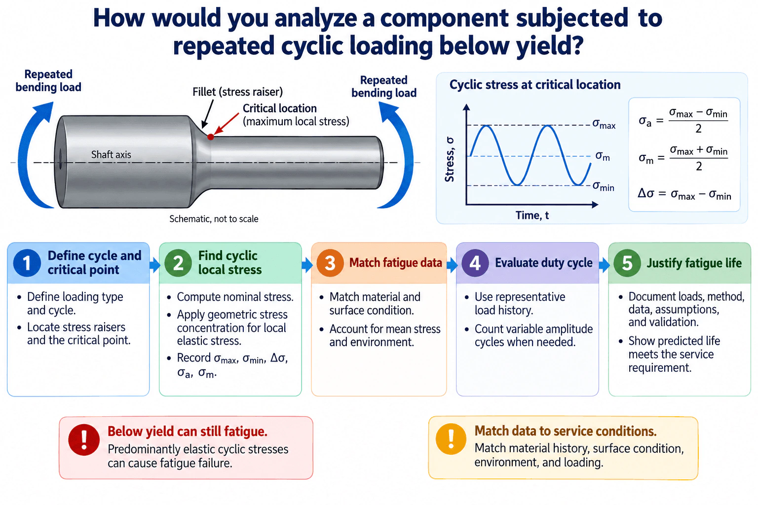
I would first define the loading cycle and locate the fatigue critical point, especially any fillet, shoulder, hole, thread, or other stress raiser. At that location I would determine σmax and σmin, then calculate Δσ = σmax − σmin, σa = (σmax − σmin) / 2, and σm = (σmax + σmin) / 2. I would account for geometric stress concentration to estimate local elastic stress, then use fatigue data that matches the material, surface condition, environment, and mean stress. Finally, I would apply the representative duty cycle, count variable amplitude cycles when needed, predict fatigue life with an appropriate method, and document the loads, method, data, assumptions, validation, and evidence that the predicted life meets the service requirement.
Detailed Explanation
Repeated cyclic loading can cause fatigue failure even when the component remains predominantly elastic and the nominal stress is below yield. The analysis should therefore focus on the local cyclic stress at the most fatigue critical location and on whether the fatigue data and duty cycle represent actual service conditions.
Useful Questions to Ask the Interviewer
What load history should I use, including the maximum load, minimum load, sequence, and required number of cycles?
What material, surface condition, geometry, manufacturing condition, and environment should I assume?
Is the duty cycle approximately constant amplitude, or does it contain variable amplitude loading that requires cycle counting?
How to Explain It in an Interview
I would begin by defining the component boundary, supports, load path, loading direction, coordinates, and operating cycle. I would check equilibrium and calculate the nominal stress caused by the applied loads.
Next, I would identify likely fatigue critical locations such as fillets, shoulders, holes, threads, or section changes. At each important location I would apply the appropriate geometric stress concentration treatment to estimate the local elastic stress. Surface condition is handled through applicable fatigue data or fatigue modification, not as part of the geometric stress concentration itself.
At the critical point I would determine the maximum and minimum cyclic stress and calculate:
Δσ = σmax − σmin
σa = (σmax − σmin) / 2
σm = (σmax + σmin) / 2
Here Δσ is the stress range, σa is the stress amplitude, and σm is the mean stress. Mean stress matters because two cycles with the same amplitude can have different fatigue severity when their mean stresses differ.
I would then match the fatigue data to the material and service condition. I would check material history, surface condition, manufacturing condition, environment, loading mode, notch treatment where applicable, and the method used to account for mean stress. I would not invent a fatigue strength or life value when the required data is unavailable.
For constant amplitude loading, I would compare the local cyclic stress with applicable fatigue data. For variable amplitude loading, I would use the representative load history and count cycles with an appropriate method such as rainflow counting before applying a suitable cumulative damage method when its assumptions are appropriate.
I would also confirm that the elastic analysis remains valid at the critical location. If the local stress causes yielding, the simple elastic fatigue treatment may no longer be adequate.
The final justification would document the loads, calculation method, fatigue data, assumptions, surface and environmental conditions, mean stress treatment, duty cycle, cycle counting method when used, predicted life, uncertainty, and validation evidence. The predicted life should then be compared with the required service life. Representative testing, strain measurement, or correlation with service data can provide stronger evidence than calculation alone.
Why Interviewers Ask This
This tests whether the candidate recognizes that cyclic stresses below yield can still cause fatigue, can identify the critical local stress history, can distinguish geometric stress concentration from surface and material effects, and can justify predicted fatigue life using representative loading, applicable fatigue data, stated assumptions, and validation evidence.
Common interview mistakes
Common mistakes include assuming that stress below yield prevents fatigue, checking only nominal stress and ignoring local stress raisers, confusing stress range with stress amplitude, ignoring mean stress, treating surface condition as part of geometric stress concentration, using fatigue data that does not represent the actual material or surface state, ignoring the actual duty cycle, failing to count variable amplitude cycles when necessary, and reporting a fatigue life without traceable assumptions or validation evidence.
Interview tip
Use the same clear sequence as the diagram: define the cycle and critical point, find the cyclic local stress, match the fatigue data, evaluate the duty cycle, and justify the fatigue life. State which inputs are known, which are assumed, and which evidence would be needed before relying on the predicted life.
Interviewer may ask next
How would you validate the fatigue life prediction before relying on it?
I would verify the load history and local stress calculation with analytical checks, measurement, or simulation correlation as appropriate. I would confirm that the fatigue data represents the actual material, surface condition, environment, manufacturing condition, and loading mode. For an important component, I would seek representative fatigue testing, strain measurements, or service correlation. I would also document uncertainty in the loads, stress concentration, fatigue data, duty cycle, and analysis assumptions rather than treating one predicted life value as exact.
What changes if the loading becomes variable amplitude instead of constant amplitude?
I would use the representative stress history rather than one maximum and minimum cycle alone. I would identify individual cycles with an appropriate cycle counting method such as rainflow counting, determine their stress ranges and mean stresses, relate those cycles to the applicable fatigue data, and use a suitable cumulative damage method when its assumptions are appropriate. I would also check whether occasional high stress cycles cause local yielding, because that could invalidate a purely elastic fatigue analysis.
3. How would galvanic corrosion change a material-selection decision?Materials And Material SelectionMedium
i Question Details
Identify dissimilar-metal couples, electrical contact, electrolyte exposure and area ratio, then consider compatible materials, isolation or coatings.
Short Interview Answer (30-60 seconds)
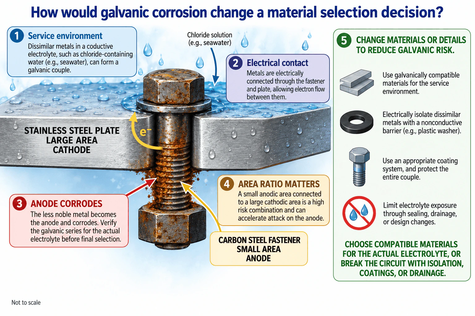
Galvanic corrosion can eliminate an otherwise acceptable material pair. I would first identify dissimilar metals that are electrically connected and exposed to the same electrolyte. Then I would check the galvanic series for that actual environment and consider the exposed cathode to anode area ratio. A small anodic member connected to a large cathodic member is especially unfavorable because corrosion can concentrate on the small anode. I would respond by selecting more compatible materials, electrically isolating the metals, protecting the joint with a qualified coating or sealant system, or reducing electrolyte exposure through sealing and drainage.
Detailed Explanation
Galvanic corrosion changes material selection because two materials that are individually acceptable can become an unacceptable pair when they are electrically connected in a conductive electrolyte. The less noble member becomes the anode and corrodes, while the more noble member acts as the cathode. The decision therefore depends on the actual material pair, service environment, electrical continuity, exposed area ratio, and required service life.
Useful Questions to Ask the Interviewer
What electrolyte or service environment should I assume, such as seawater, condensation, or occasional splash?
Are the metals in direct electrical contact, or can the joint use an insulating barrier or sealant?
What areas of each metal are exposed to the electrolyte, and which component is most critical to service life?
How to Explain It in an Interview
I would start by identifying every dissimilar metal couple and defining the service environment. Galvanic corrosion requires both an electrical path between the materials and a shared conductive electrolyte, so I would confirm those conditions first.
For the illustrated chloride example, the large stainless steel plate is the cathodic member and the smaller carbon steel fastener is the anodic member. Electrons flow through the metallic path from the anodic carbon steel fastener toward the stainless steel plate. The fastener therefore experiences the accelerated anodic attack shown in the diagram. I would verify this polarity using galvanic data for the actual electrolyte and material condition before final selection.
Area ratio is a major part of the decision. A small exposed anode connected to a large exposed cathode is unfavorable because the galvanic current is concentrated over the smaller anodic area. In this example, that means the carbon steel fastener can suffer severe localized attack even though the much larger stainless steel plate remains comparatively protected.
My first preference would be to choose materials with better galvanic compatibility for the actual service environment. If the dissimilar materials must remain, I would consider electrically isolating them with a nonconductive washer, sleeve, or barrier. I would also evaluate a qualified coating or sealant system that protects the joint and limits electrolyte access. Drainage and sealing matter because removing persistent electrolyte exposure can prevent the galvanic cell from remaining active.
Before release, I would verify the material condition, galvanic compatibility, exposed area ratio, coating or isolation durability, and the effect of the corrosion strategy on strength, stiffness, toughness, fatigue, temperature capability, and service life. The final selection must satisfy both mechanical requirements and corrosion compatibility.
Why Interviewers Ask This
Interviewers want to see whether I treat corrosion compatibility as part of material selection rather than checking strength or corrosion resistance of each material independently. The key judgment is recognizing a dissimilar metal couple, confirming electrical contact and electrolyte exposure, identifying the anodic member, considering exposed area ratio, and then changing the material pair or protection strategy before final selection.
Common interview mistakes
Common mistakes are evaluating each material in isolation, ignoring electrical contact, using galvanic data for the wrong environment, overlooking exposed area ratio, assuming any coating automatically solves the problem, and failing to consider what happens if a coating or isolation barrier is damaged during service.
Interview tip
State the decision sequence clearly: identify the dissimilar metal couple, confirm electrical contact and electrolyte exposure, determine which member is anodic in the actual environment, assess cathode to anode area ratio, then choose compatible materials or interrupt the galvanic path with isolation, coatings, sealing, or drainage. Finish by confirming that the selected solution still satisfies the required mechanical properties and service life.
Interviewer may ask next
How would you validate that the selected material pair is acceptable before release?
I would verify galvanic compatibility using data for the actual electrolyte and material condition, confirm the exposed cathode to anode area ratio, review the electrical isolation or coating scheme, and use representative corrosion testing when uncertainty or consequence justifies it. I would also confirm that the protection method does not compromise strength, fatigue performance, temperature capability, maintenance access, or required life.
What would you do if the carbon steel fastener and stainless steel plate both had to remain?
I would focus on interrupting or weakening the galvanic cell. I would evaluate a nonconductive washer and sleeve system, seal the joint against electrolyte ingress, use a qualified protective coating or sealant system, and provide drainage so chloride solution cannot remain trapped. I would pay particular attention to maintaining protection of the small anodic fastener because a small exposed anode connected to the large cathodic plate can experience concentrated attack.
4. How would you choose a material for a component operating at elevated temperature in a corrosive environment?Materials And Material SelectionMedium
i Question Details
Screen candidates for temperature-dependent strength, oxidation or corrosion mechanisms, thermal expansion, manufacturability, joining, availability and total cost.
Short Interview Answer (30-60 seconds)
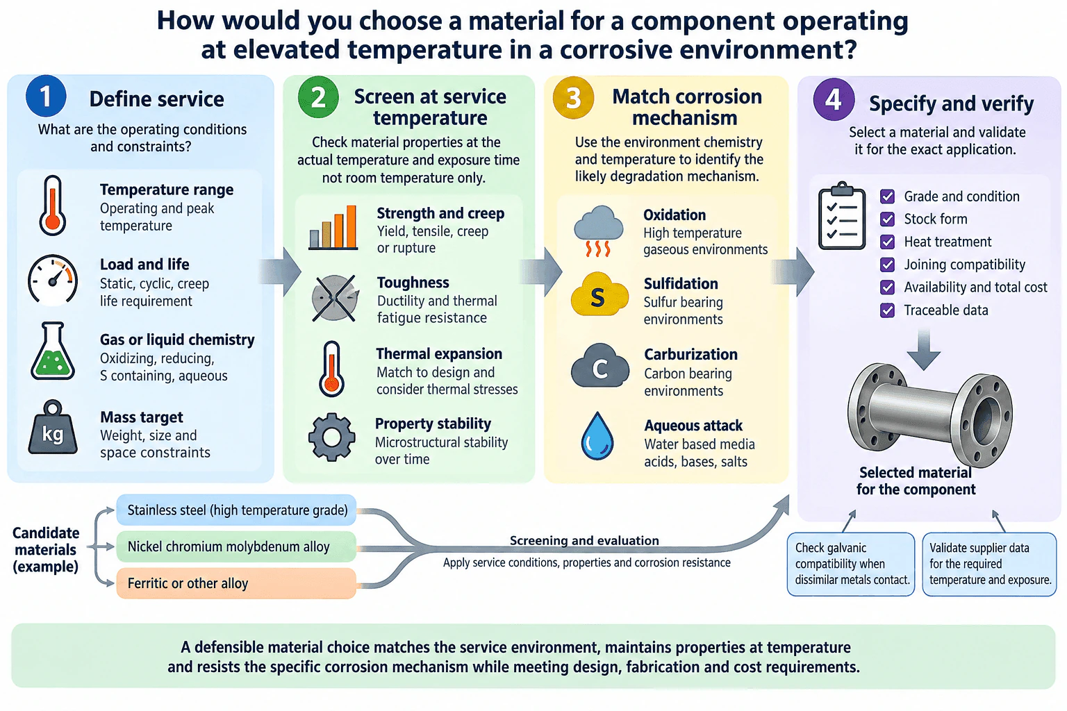
I would start by defining the operating and peak temperature, load and life, gas or liquid chemistry, and mass target. I would then screen candidates using property data at the actual service temperature, checking strength, creep resistance, toughness, thermal expansion, thermal fatigue resistance, and material stability. Next I would match the environment to the likely corrosion mechanism, such as oxidation, sulfidation, carburization, or aqueous attack. I would finish by specifying the exact grade and condition, stock form, heat treatment, joining compatibility, availability, total cost, galvanic compatibility where relevant, and traceable data for the required temperature and exposure.
Detailed Explanation
I would treat this as a service condition screening problem. The selected material must retain the required mechanical properties at temperature and resist the specific degradation mechanism for the required life. I would not select a material from room temperature strength or a generic corrosion rating alone.
Useful Questions to Ask the Interviewer
What are the operating and peak temperatures, exposure duration, load type, and required life?
What gas or liquid chemistry is present, including oxidizing or reducing conditions, sulfur bearing species, carbon bearing species, water, acids, bases, or salts?
Are there constraints on mass, joining method, stock form, availability, or total cost?
How to Explain It in an Interview
Engineering Method
First, I would define the service envelope. That includes normal and peak temperature, static or cyclic loading, any creep life requirement, environment chemistry, exposure time, and mass target. These become the material screening requirements.
Second, I would compare candidates using property data at the actual service temperature. I would check yield and tensile strength where relevant, creep or rupture behavior for sustained loading, toughness and ductility, thermal fatigue resistance for cyclic temperature exposure, thermal expansion, stiffness where deflection matters, density where mass matters, and stability of the material condition over time. Thermal expansion matters because mismatch or restraint can create additional thermal stress.
Third, I would identify the likely corrosion mechanism from temperature and chemistry. A high temperature gaseous environment may be controlled by oxidation. Sulfur bearing environments may require sulfidation resistance. Carbon bearing environments may raise carburization concerns. Water based environments may involve aqueous corrosion from acids, bases, salts, or other species.
Fourth, I would narrow the candidates and specify the exact grade, material condition, stock form, and heat treatment. I would also check joining compatibility, availability, total cost, and expected property variability. If dissimilar metals contact each other in a conductive environment, I would evaluate galvanic compatibility.
Assumptions And Checks
I would not assume one alloy family is universally best. I would use traceable material data that matches the required temperature, exposure, environment, stock form, heat treatment, and material condition. I would also verify that any candidate comparison uses comparable conditions rather than mixing room temperature and elevated temperature data.
Design Reasoning
A defensible choice is the material that maintains the required properties at temperature, resists the governing corrosion mechanism, and still satisfies joining, availability, mass, and total cost constraints. Before release, I would validate the selection using applicable material certificates, supplier data, and service relevant evidence.
Why Interviewers Ask This
The interviewer is testing whether I can translate service temperature, load, life, environment, and mass targets into material requirements, evaluate temperature dependent mechanical behavior, identify the governing corrosion mechanism, compare candidates using comparable and traceable evidence, and make a practical selection that also accounts for material condition, joining, availability, and total cost.
Common interview mistakes
Common mistakes include using room temperature strength data for elevated temperature service, treating corrosion resistance as one universal property, ignoring creep or rupture behavior, overlooking thermal expansion, thermal fatigue, or material stability, failing to specify the exact grade and material condition, ignoring galvanic compatibility where dissimilar metals contact, and relying on property data that is not traceable to the required temperature and exposure.
Interview tip
Explain the decision in a clear sequence: define service conditions, screen properties at temperature, identify the corrosion mechanism, then specify and verify the exact material condition. Avoid naming a preferred alloy before the temperature, chemistry, life, load, and joining requirements are known.
Interviewer may ask next
What would you validate before releasing the final material selection?
I would verify that the mechanical and corrosion data correspond to the intended temperature, exposure time, environment, grade, stock form, heat treatment, and material condition. I would confirm joining compatibility, availability, total cost, and property traceability. I would also check galvanic compatibility where dissimilar metals are present and seek service relevant evidence if creep, thermal fatigue, or corrosion uncertainty could control component life.
How would your selection process change if reducing component mass became a major requirement?
I would give density more weight in the candidate comparison while keeping the service requirements unchanged. A lower density material would only be preferred if it still provides adequate strength, stiffness where required, creep resistance, toughness, thermal fatigue resistance, thermal stability, corrosion resistance, joining compatibility, availability, and acceptable total cost in the specified material condition.
5. How would you distinguish fatigue failure from stress-corrosion cracking during material selection or failure review?Materials And Material SelectionHard
i Question Details
Compare cyclic-load dependence, environmental sensitivity, crack morphology, material susceptibility and the evidence needed to separate the two mechanisms.
Short Interview Answer (30-60 seconds)
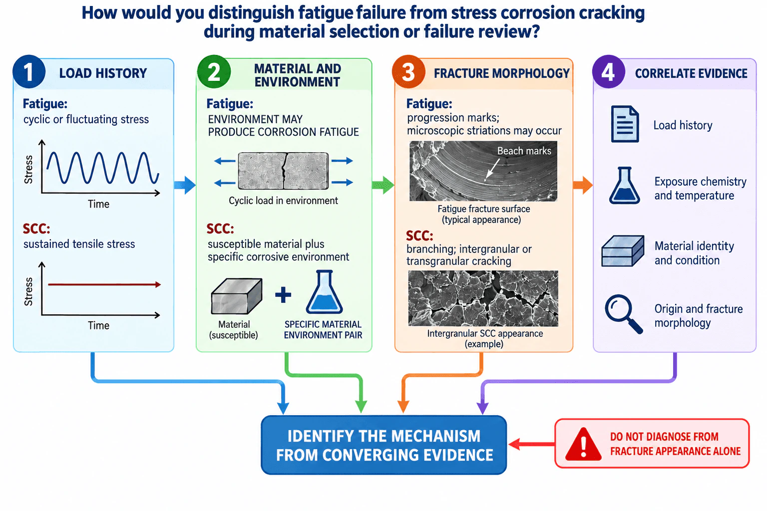
I would distinguish them by correlating four evidence groups. Fatigue depends on cyclic or fluctuating stress. Stress corrosion cracking requires tensile stress together with a susceptible material and a specific corrosive environment. Fatigue may show progression marks and microscopic striations, while stress corrosion cracking may show branching and either intergranular or transgranular cracking. I would then correlate load history, exposure chemistry and temperature, material identity and condition, crack origin, and fracture morphology. I would not diagnose either mechanism from fracture appearance alone.
Detailed Explanation
The key is to identify the mechanism from converging evidence rather than from one fracture feature. Fatigue and stress corrosion cracking can both produce progressive cracking, but their required conditions and supporting evidence differ.
Useful Questions to Ask the Interviewer
What was the actual load history, including whether the component experienced cyclic or fluctuating stress or mainly sustained tensile stress?
What material, material condition, heat treatment, temperature, and chemical environment were present?
What evidence is available from the crack origin, fracture surface, metallography, and service records?
How to Explain It in an Interview
Engineering Method
I would start with load history. Fatigue requires cyclic or fluctuating stress. Stress corrosion cracking requires tensile stress acting together with a susceptible material and a specific corrosive environment. The tensile stress can include residual stress, so I would review both applied and residual stress sources.
Next I would examine the material and environment pair. For fatigue, an environment can accelerate cracking and may produce corrosion fatigue, but cyclic loading remains fundamental. For stress corrosion cracking, I need evidence that the specific material condition is susceptible in the actual environment. I would confirm alloy identity, material condition, heat treatment, exposure chemistry, and temperature.
Then I would examine fracture morphology. Fatigue can produce macroscopic progression marks and microscopic striations, although these features are not always present or visible. Stress corrosion cracking may show branching and may propagate intergranularly or transgranularly depending on the material and environment. Morphology therefore supports the diagnosis but does not establish it by itself.
Assumptions And Checks
I would verify material traceability, loading records, environmental exposure, temperature, crack origin, and fracture morphology. Where appropriate, I would compare fractography with metallography. If the evidence remains ambiguous, representative testing under relevant loading and environmental conditions can challenge the proposed mechanism.
Design Reasoning
For material selection, a fatigue concern requires suitable fatigue performance for the expected load spectrum and service environment. A stress corrosion cracking concern requires compatibility among the material condition, tensile stress state, temperature, and specific environment. The final conclusion should come from agreement among load history, the material and environment pair, fracture morphology, and corroborating evidence.
Why Interviewers Ask This
Interviewers are testing whether I can distinguish two crack growth mechanisms that may appear similar in service, connect observed damage to loading, environment, material condition, and fracture evidence, and make a defensible material selection or failure review decision without relying on fracture appearance alone.
Common interview mistakes
Common mistakes are diagnosing the mechanism from fracture appearance alone, assuming any corrosion means stress corrosion cracking, ignoring residual tensile stress, overlooking the specific material and environment pair, treating fatigue only as a static strength problem, failing to confirm material condition or heat treatment, and comparing material data obtained under conditions that do not represent the actual service case.
Interview tip
Organize the answer around four evidence groups: load history, material and environment, fracture morphology, and evidence correlation. State early that fatigue depends on cyclic loading, while stress corrosion cracking requires tensile stress plus a susceptible material and a specific corrosive environment. Finish by explaining that the mechanism should be identified from converging evidence rather than from fracture appearance alone.
Interviewer may ask next
What would you do if both cyclic loading and a corrosive environment were present?
I would not force the failure into one category before reviewing the full evidence. I would characterize the cyclic loading, environment, material condition, crack origin, and fracture morphology. Corrosion fatigue may occur when the environment accelerates fatigue under cyclic loading, while stress corrosion cracking requires the appropriate combination of tensile stress, susceptible material, and specific environment. I would select the mechanism best supported by the complete evidence.
How would your material selection change if the component had mainly sustained tensile stress in a known aggressive environment instead of repeated loading?
I would place greater emphasis on resistance to stress corrosion cracking for that exact material condition and environment. I would verify alloy and heat treatment susceptibility, exposure chemistry, temperature, applied and residual tensile stresses, toughness, and traceable property data. Strong general corrosion resistance alone would not prove suitability because stress corrosion cracking depends on the specific interaction among material, tensile stress, and environment.
6. What is the purpose of a bearing in a rotating assembly?Machine Elements And MechanismsEasy
i Question Details
Explain how a bearing supports relative motion and loads at a shaft interface and distinguish radial and axial loading needs.
Short Interview Answer (30-60 seconds)
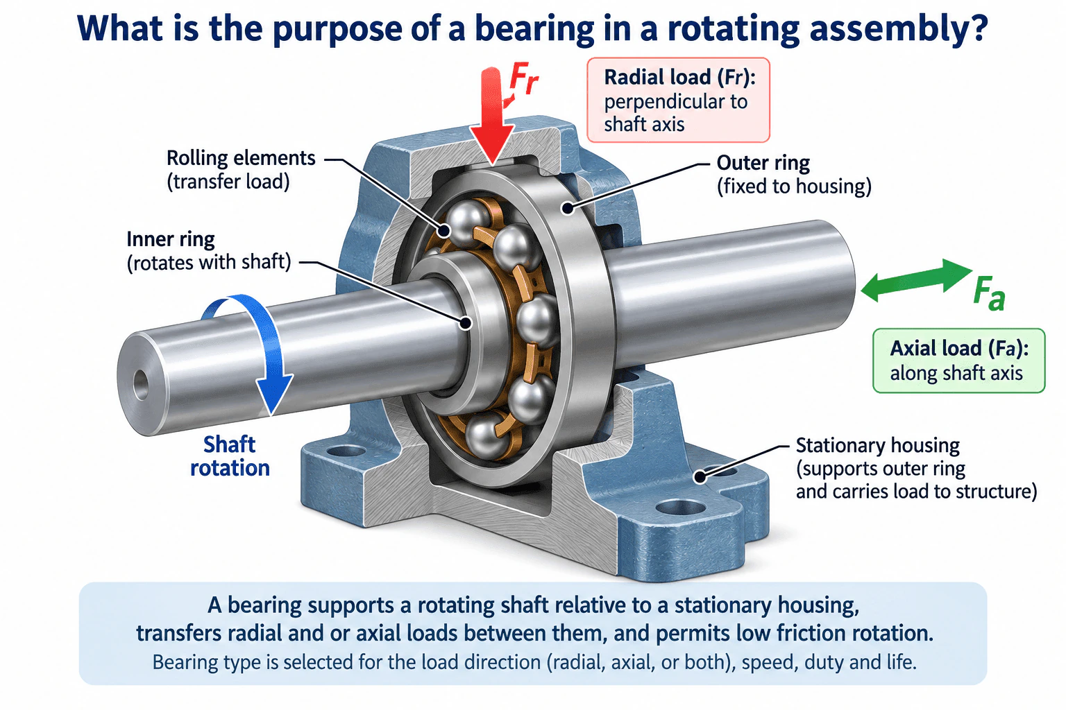
A bearing supports a rotating shaft relative to a stationary housing while allowing low friction relative motion. In a typical rolling bearing, the inner ring rotates with the shaft, the rolling elements transfer load between the rings, and the outer ring is supported by the housing. Radial load acts perpendicular to the shaft axis, while axial load acts along the shaft axis. The bearing type is selected for the required load direction, speed, duty cycle, life, lubrication, alignment, fit, and retention.
Detailed Explanation
A bearing creates a controlled interface between a rotating shaft and a stationary housing. Its purpose is to support the shaft, permit the required rotation with low friction, and transfer loads from the shaft through the bearing into the housing and supporting structure.
In a typical rolling bearing, the inner ring rotates with the shaft. The rolling elements transfer load between the inner and outer rings. The outer ring is supported by the stationary housing. A radial load, Fr, acts perpendicular to the shaft axis. An axial load, Fa, acts along the shaft axis. The selected bearing must have suitable capacity for the actual load direction or combination of directions.
Useful Questions to Ask the Interviewer
Is the dominant load radial, axial, or a combination of both?
What shaft speed, duty cycle, and required bearing life should be considered?
Are there important constraints on lubrication, alignment, fit, or axial retention?
How to Explain It in an Interview
Engineering Method
I would first define the required relative motion and the load path. The shaft must rotate relative to the stationary housing, so the bearing must support the shaft while permitting that degree of freedom. I would then identify the radial and axial loads and define the speed, duty cycle, and required life.
Design Reasoning
For radial loading, the force acts perpendicular to the shaft axis. The load is transferred from the shaft through the inner ring, rolling elements, outer ring, and housing. For axial loading, the force acts along the shaft axis, so the selected bearing must provide suitable axial load capacity in the required direction or directions.
The bearing also helps locate and support the shaft. Proper shaft and housing fits keep the rings correctly mounted. Retention controls unwanted axial movement. Lubrication reduces friction and wear at the rolling contacts. Alignment is important because excessive misalignment can create unfavorable contact loading and reduce service life.
Assumptions And Checks
I would not select a bearing from bore size or load direction alone. I would confirm the actual loads, speed, operating temperature, duty cycle, target life, lubrication method, available space, alignment capability, fits, and retention arrangement. I would then compare those requirements with manufacturer bearing data and the applicable bearing life method.
Credible failure modes include rolling contact fatigue, wear, inadequate lubrication, contamination, excessive temperature, misalignment, and loss of proper fit or retention. The final selection should therefore support the required motion and provide a reliable load path from the rotating shaft into the stationary structure.
Why Interviewers Ask This
Interviewers want to see whether the candidate understands how a bearing permits controlled relative motion while supporting a shaft and transferring loads into the surrounding structure. They also want to see whether the candidate can distinguish radial loading from axial loading and recognize the operating conditions that affect bearing selection.
Common interview mistakes
Common mistakes include treating every bearing as suitable for the same load direction, ignoring axial load, selecting only from a single load value, overlooking speed and duty cycle, neglecting lubrication and contamination, using unsuitable shaft or housing fits, ignoring alignment, and failing to provide appropriate axial retention.
Interview tip
Start with the physical purpose: the bearing lets the shaft rotate while supporting it and carrying load into the housing. Then distinguish radial load from axial load and explain that the final bearing choice depends on load direction, speed, duty cycle, life, lubrication, alignment, fit, and retention.
Interviewer may ask next
What would you check before selecting a specific bearing for this shaft interface?
I would define the radial and axial loads, shaft speed, duty cycle, required life, operating temperature, available space, lubrication method, contamination exposure, alignment capability, shaft and housing fits, and retention method. I would then compare those requirements with the selected bearing type and manufacturer data rather than choosing from bore size alone.
How would the bearing decision change if the assembly developed a significant axial load?
I would verify that the selected bearing has adequate axial load capacity in the required direction or directions. If the original bearing arrangement was intended mainly for radial loading, I would select a bearing type or bearing arrangement that can support the added axial load while still meeting the required speed, life, lubrication, alignment, fit, and retention conditions.
7. How would you size a shaft that carries torque and bending load?Machine Elements And MechanismsMedium
i Question Details
Use the torque, bending moment, material, fatigue-sensitive features, bearing spacing, allowable stress and deflection to determine a shaft diameter.
Short Interview Answer (30-60 seconds)
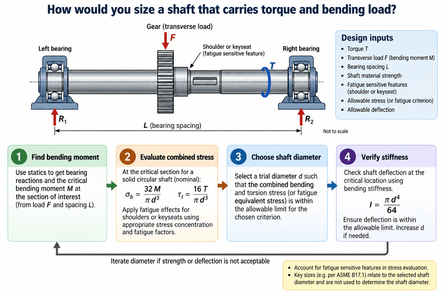
I would first define the transmitted torque T, transverse loads, bearing locations and spacing L, material, duty cycle, life requirement, allowable stress or fatigue criterion, and allowable deflection. I would use statics to calculate the bearing reactions and critical bending moment M. For a solid circular shaft, the nominal bending stress is 32M divided by πd³ and the nominal torsional shear stress is 16T divided by πd³. I would then account for fatigue sensitive features such as shoulders or keyseats, select a trial diameter using an appropriate combined stress or fatigue criterion, and verify shaft deflection using its bending stiffness. If either strength or deflection is unacceptable, I would revise the diameter or geometry and repeat the checks.
Detailed Explanation
A shaft carrying torque and transverse load must satisfy both strength and stiffness requirements. I would treat the shaft and bearings as one load path, find the critical bending section, combine bending and torsional stresses with a suitable design criterion, then check whether the selected diameter also meets the allowable deflection.
Useful Questions to Ask the Interviewer
What torque, transverse loads, bearing locations, speed, duty cycle, and required life should I use?
What shaft material and allowable stress or fatigue criterion should govern the design?
Are there shoulders, keyseats, retaining features, fits, or deflection limits that must be included?
How to Explain It in an Interview
Engineering Method
Let T be transmitted torque, M the critical bending moment, L the bearing spacing, d the shaft diameter, E the elastic modulus, and I the second moment of area. I first draw the shaft load path, apply the transverse loads, and use statics to calculate the bearing reactions. From those reactions and load locations I determine the bending moment distribution and identify the critical section.
For a solid circular shaft, the nominal outer surface stresses are:
σb = 32M divided by πd³
τt = 16T divided by πd³
For a ductile material under a static combined load, one possible criterion is von Mises stress:
σvm = √(σb² + 3τt²)
Using the nominal stresses gives a trial strength diameter from:
d ≥ [16√(4M² + 3T²) divided by (πσallow)]^(1/3)
The actual criterion must match the material, load history, and design requirements. At shoulders, keyseats, or other fatigue sensitive locations, I include the appropriate stress concentration and fatigue effects rather than relying only on nominal stress.
Design Reasoning
Bearing spacing and load location affect the reactions, bending moment, and deflection. Increasing d strongly reduces both bending and torsional stress because each varies with 1 divided by d³.
Strength alone is not sufficient. For a solid circular shaft:
I = πd⁴ divided by 64
I use EI with the actual support and loading conditions to calculate shaft deflection at the critical location and compare it with the specified allowable value. Because stiffness varies strongly with diameter, a deflection requirement can govern even when the stress check passes.
Assumptions And Checks
I verify equilibrium, units, load directions, the critical section, material data, fatigue sensitive geometry, and the applicable deflection limit. I also confirm that a key size is selected to suit the chosen shaft diameter rather than using the key size to establish the shaft diameter. If a particular key standard such as ASME B17.1 is required, I verify the applicable edition before using it. If either strength or deflection fails, I increase the diameter or revise the geometry and repeat the calculation.
Why Interviewers Ask This
Interviewers want to see whether I can translate a real shaft load path into a defensible diameter using statics, combined bending and torsion, material limits, fatigue sensitive geometry, and stiffness. They are also checking whether I recognize that a shaft which passes a nominal stress calculation can still fail the design because of shoulders, keyseats, bearing spacing, fatigue, or excessive deflection.
Common interview mistakes
Common mistakes include sizing from torque alone, ignoring the bending moment created by transverse loads and bearing geometry, using nominal stress at a shoulder or keyseat without accounting for fatigue effects, inventing a material strength or design margin, mixing unit systems, checking strength but not deflection, and assuming the key size determines the shaft diameter.
Interview tip
Start with the load path instead of immediately writing a diameter equation. Show how the transverse load creates bearing reactions and bending moment, explain how torque and bending act together at the critical section, then state that the final diameter must pass both the strength or fatigue criterion and the deflection check.
Interviewer may ask next
How would you validate that the selected shaft diameter is adequate before release?
I would independently verify the load cases, reactions, bending moment, torque, units, material properties, and critical sections. I would check the chosen allowable stress or fatigue criterion at shoulders and keyseats, calculate deflection using the actual support and loading conditions, and confirm that fits, alignment, retention, and bearing interfaces remain practical. For a real component I would also compare the analytical model with appropriate detailed analysis or test evidence when the uncertainty or consequence of failure justifies it.
What changes if the bearing spacing increases while the transmitted torque stays the same?
The torsional stress contribution does not change merely because the bearing spacing changes, but the bending response generally changes because the support geometry changes the reactions and bending moment. If the critical bending moment increases, the required diameter may increase. A longer span can also increase deflection, so stiffness can become the governing constraint even if the combined stress remains acceptable.
8. How would you select a bearing for a shaft with combined radial and axial load?Machine Elements And MechanismsMedium
i Question Details
Define load direction and magnitude, speed, duty cycle, life, stiffness, misalignment, lubrication, environment and packaging before selecting bearing type and size.
Short Interview Answer (30-60 seconds)
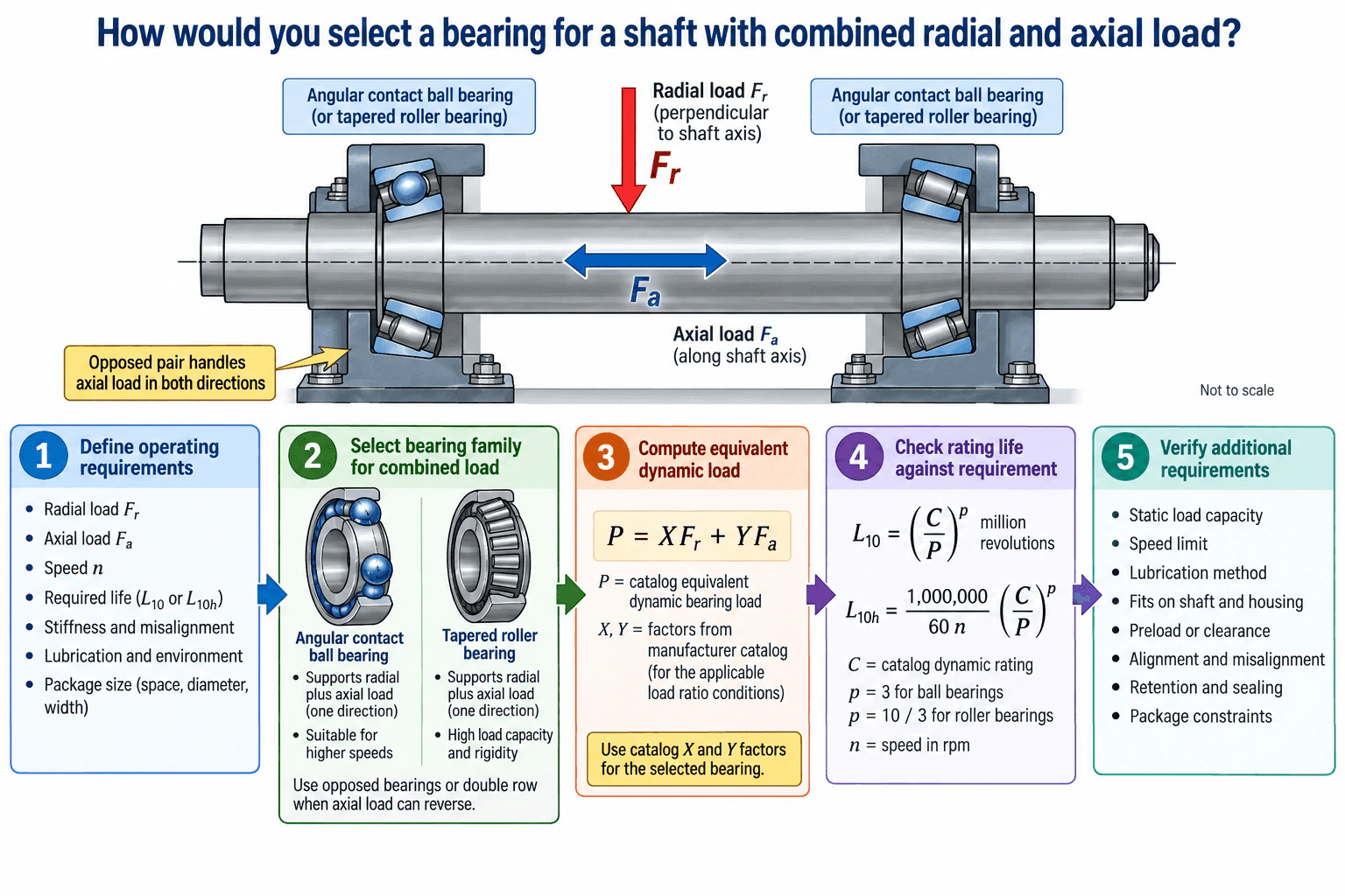
I would first define radial load Fᵣ, axial load Fₐ, their directions, speed n, duty cycle, required life, stiffness, expected misalignment, lubrication, environment, and available space. For substantial combined loading I would consider an angular contact ball bearing or tapered roller bearing. If axial load can reverse, I would use an opposed pair or a suitable double row arrangement. I would calculate the catalog equivalent dynamic load P = XFᵣ + YFₐ, select a dynamic rating C that satisfies the required L₁₀ life, then verify static capacity, speed limit, fits, preload or clearance, alignment, lubrication, retention, sealing, and package constraints.
Detailed Explanation
A bearing should be selected from the actual load path and operating conditions rather than from shaft diameter alone. For a shaft with combined radial and axial loading, I would define the operating requirements, choose a bearing family that can support the load directions, calculate equivalent dynamic load and rating life, then verify the installation and environmental requirements.
Useful Questions to Ask the Interviewer
What are the maximum and representative radial load Fᵣ and axial load Fₐ, and can the axial load reverse direction?
What shaft speed, duty cycle, and required bearing life should I design for?
What limits apply to stiffness, misalignment, lubrication, contamination, temperature, shaft diameter, housing diameter, and available width?
How to Explain It in an Interview
I would define the shaft axis and separate the applied load into radial load Fᵣ, perpendicular to the shaft axis, and axial load Fₐ, parallel to the shaft axis. I would also define speed n, duty cycle, required life, stiffness, expected misalignment, lubrication, environment, and package limits.
For significant combined loading, two common candidates are angular contact ball bearings and tapered roller bearings. An angular contact ball bearing supports radial load plus axial load primarily in one direction and is often useful when higher speed capability is important. A tapered roller bearing also supports combined load and generally provides high load capacity and rigidity. If axial load can act in either direction, I would use an opposed pair or an appropriate double row arrangement.
After choosing the bearing family, I would use the manufacturer catalog factors for the applicable load ratio to determine equivalent dynamic bearing load:
P = XFᵣ + YFₐ
Here P is equivalent dynamic bearing load, while X and Y are catalog factors for the selected bearing and loading condition.
I would then check basic rating life. In millions of revolutions:
L₁₀ = (C / P)ᵖ
For constant speed n in rpm, life in hours is:
L₁₀h = 1,000,000 / (60n) × (C / P)ᵖ
C is the catalog dynamic load rating. The exponent p is 3 for ball bearings and 10 / 3 for roller bearings.
Finally, I would verify static load capacity, speed limit, lubrication method, shaft and housing fits, preload or internal clearance, alignment, retention, sealing, contamination protection, and available space. I would also confirm that the arrangement supports the required axial direction and that preload does not create unacceptable friction or heat. The selected bearing must satisfy both the calculated life requirement and the practical installation conditions.
Why Interviewers Ask This
Interviewers want to see whether the candidate can convert radial load, axial load, speed, duty cycle, required life, stiffness, alignment, lubrication, environment, and packaging constraints into a defensible bearing type and size. They are also testing understanding of equivalent dynamic load, bearing life, bearing arrangement, and practical installation checks.
Common interview mistakes
Common mistakes include selecting a bearing only from shaft diameter, ignoring axial load direction, using radial load alone in the life calculation, applying X and Y factors from the wrong catalog condition, assuming one angular contact or tapered roller bearing carries axial load equally in both directions, ignoring static capacity or speed limits, and overlooking fits, preload, lubrication, alignment, sealing, retention, contamination, and available space.
Interview tip
State the load path first, then move through bearing family, equivalent dynamic load, rating life, and installation checks. Define Fᵣ, Fₐ, P, C, n, X, Y, and p before using them. Explain why the selected bearing arrangement supports the required axial direction rather than naming a bearing type without justification.
Interviewer may ask next
How would you validate the bearing selection before releasing the design?
I would verify the manufacturer catalog calculations using the actual radial and axial load cases, speed, duty cycle, and required life. I would check dynamic and static ratings, speed limit, lubrication, fits, internal clearance or preload, alignment, retention, sealing, and package dimensions. I would also review credible failure modes such as excessive temperature, lubrication breakdown, contamination, surface fatigue, excessive clearance, and excessive preload. Where appropriate, representative testing would confirm temperature, vibration, noise, and bearing condition under expected operating loads.
How would the selection change if the axial load reversed direction during operation?
A single angular contact ball bearing or tapered roller bearing normally carries axial load primarily in one direction, so reversing axial load changes the required arrangement. I would use an opposed bearing pair or an appropriate double row bearing so axial load can be reacted in both directions. I would then evaluate the governing load in each direction, recalculate equivalent dynamic load and life, verify static capacity, and review preload or clearance because the arrangement also affects stiffness, friction, heat generation, and alignment sensitivity.
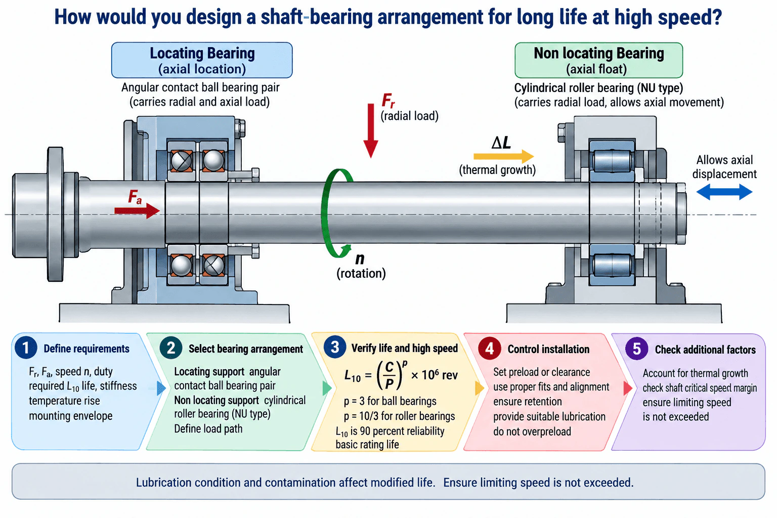
9. How would you design a shaft-bearing arrangement for long life at high speed?Machine Elements And MechanismsHard
i Question Details
Set radial and axial loads, speed, required L10 life, stiffness, thermal growth, lubrication, fit, preload or clearance, critical speed and mounting constraints.
Short Interview Answer (30-60 seconds)
I would first define radial load Fr, axial load Fa, operating speed n, duty cycle, required L10 life, stiffness, temperature rise, and mounting constraints. I would use an angular contact ball bearing pair at the locating end to carry radial and axial load and establish shaft axial position. At the opposite end, I would use an NU cylindrical roller bearing to carry radial load while allowing axial thermal displacement. I would calculate equivalent bearing load and L10 life, check bearing limiting speed and shaft critical speed, then set appropriate preload or clearance, fits, alignment, retention, lubrication, and sealing. Finally, I would validate temperature, vibration, axial movement, and bearing condition under representative loads and speeds.
Detailed Explanation
The main design goal is to support the rotating shaft radially, locate it axially at one end, and allow thermal growth at the other end without creating damaging internal bearing loads. At high speed, bearing life alone is not enough. Stiffness, preload, lubrication, heat generation, alignment, fits, and shaft dynamics all matter.
Useful Questions to Ask the Interviewer
What are the radial load Fr, axial load Fa, operating speed n, duty cycle, and required L10 life?
What shaft stiffness, axial location accuracy, temperature rise, and thermal growth must the arrangement accommodate?
What mounting envelope, lubrication method, contamination level, fit constraints, and allowable vibration limits apply?
How to Explain It in an Interview
1. Define requirements and the load path
I would establish Fr, Fa, speed n, duty cycle, life target, stiffness target, temperature range, and mounting constraints. I would identify where axial location must be controlled and the direction in which shaft thermal growth can be allowed.
2. Choose the bearing arrangement
I would use an angular contact ball bearing pair at the locating end. This pair carries radial and axial load and establishes the shaft axial position. At the opposite end, I would use an NU cylindrical roller bearing. It supports radial load while permitting relative axial displacement between its rings, so shaft thermal growth ΔL does not create excessive axial bearing load.
3. Verify bearing life
For each bearing, I would determine the equivalent dynamic bearing load P and compare it with the basic dynamic load rating C. The basic rating life is
L10 = (C/P)^p × 10^6 revolutions
For ball bearings, p = 3. For roller bearings, p = 10/3. L10 represents the basic rating life associated with 90 percent reliability for a sufficiently large group of apparently identical bearings under the rating assumptions. I would also consider lubrication condition and contamination because actual service life can differ from the basic rating life.
4. Set preload, clearance, fits, and alignment
The angular contact pair needs suitable preload or operating clearance to provide stiffness without excessive friction and temperature rise. Shaft and housing fits must retain the rings against creep while maintaining the intended internal clearance. Shoulders and retention features must locate the rings correctly, and alignment must avoid unintended edge loading.
5. Check speed, thermal behavior, and dynamics
I would select lubrication appropriate for speed, load, temperature, and heat removal, with effective sealing and contamination control. I would confirm that operating speed stays within the applicable bearing speed limit, verify adequate separation from shaft critical speed, and confirm that the non locating end has enough axial freedom for thermal growth.
Validation
I would measure bearing temperature, vibration, shaft displacement, axial movement, lubrication condition, and retention during representative load and speed testing. I would compare those results with the design assumptions and revise preload, clearance, fits, lubrication, shaft stiffness, or bearing selection if excessive heat, vibration, or internal loading appears.
Why Interviewers Ask This
Interviewers want to see whether I can convert radial load, axial load, speed, life, stiffness, temperature, lubrication, and mounting constraints into a defensible shaft support arrangement. They are testing whether I understand bearing life, axial location, thermal growth, preload or clearance, fits, alignment, lubrication, critical speed, and realistic failure modes rather than selecting a bearing only from a catalog rating.
Common interview mistakes
Common mistakes include sizing bearings from radial load alone, ignoring axial load and duty cycle, treating L10 as a guaranteed service life, restraining thermal growth at both ends, applying excessive angular contact preload, selecting fits without considering changes in internal clearance, ignoring misalignment, using inadequate lubrication or sealing, overlooking contamination, and checking bearing speed capability without also checking shaft critical speed.
Interview tip
Explain the design as a load path and constraint problem. Start with Fr, Fa, speed, duty cycle, life, stiffness, and temperature. Then state which bearing locates the shaft axially, which bearing allows thermal movement, how L10 life and speed capability are checked, and how preload, fits, lubrication, alignment, and shaft dynamics are validated.
Interviewer may ask next
How would you validate that the non locating bearing is accommodating thermal growth as intended?
I would estimate the expected shaft thermal growth from geometry and temperature change, then verify during testing that axial displacement occurs at the non locating support without abnormal axial force, temperature rise, or vibration. I would also confirm that fits and retention features do not accidentally restrain the intended axial movement.
What would you change if the required operating speed increased substantially?
I would recalculate bearing life and speed capability, shaft critical speed, lubrication requirements, heat generation, and preload effects. I might reduce preload, change bearing size or internal design, improve balance and alignment, use lubrication better suited to higher speed, or revise shaft geometry to increase dynamic stiffness while retaining the locating and non locating thermal growth strategy if the revised loads still support it.
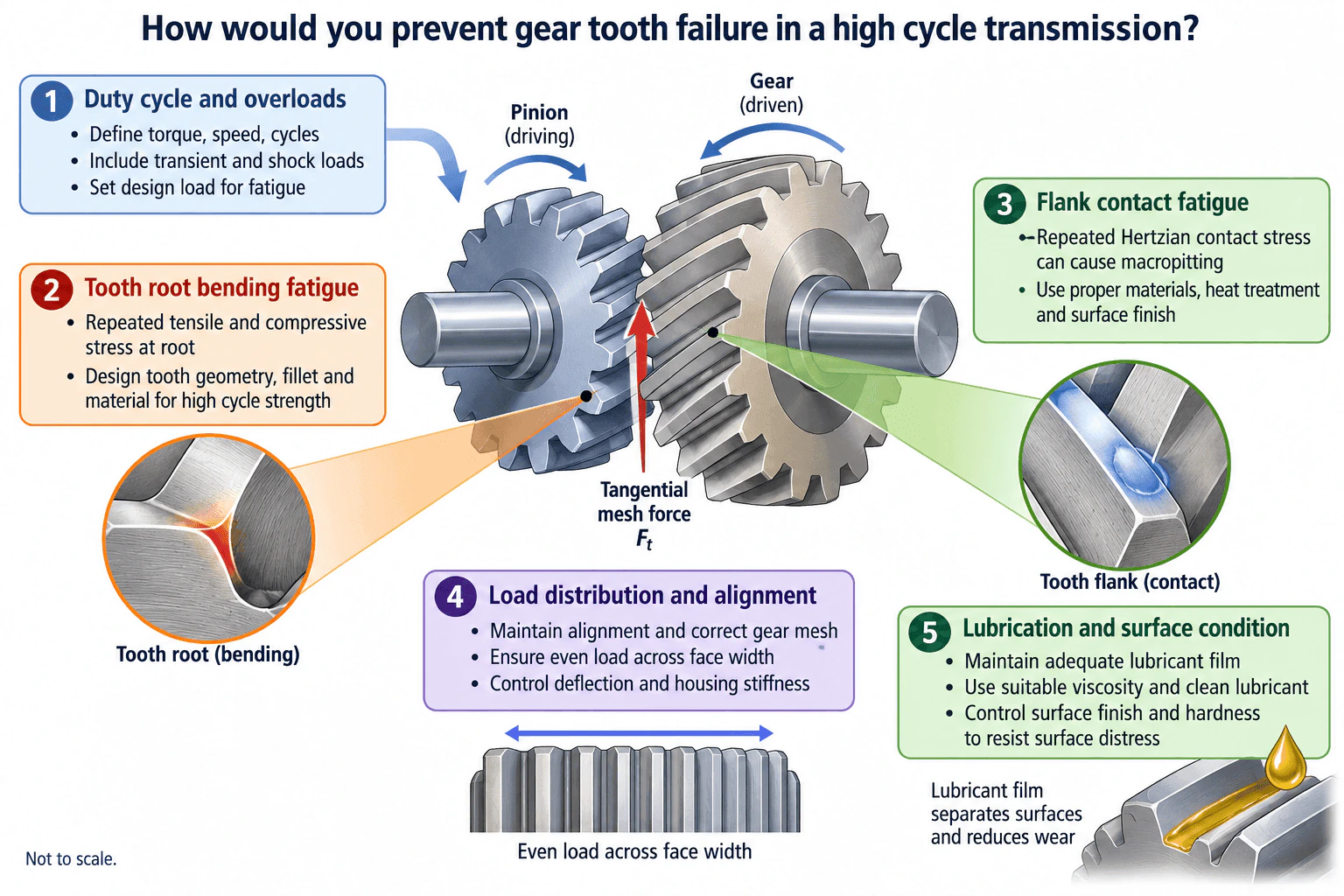
10. How would you prevent gear-tooth failure in a high-cycle transmission?Machine Elements And MechanismsHard
i Question Details
Check bending fatigue, contact fatigue, lubrication, alignment, surface finish, hardness, load distribution and transient overloads before finalizing geometry and material.
Short Interview Answer (30-60 seconds)
I would start with the actual torque, speed, cycle count, required life, and credible transient or shock loads. From the transmitted torque I would determine the tangential mesh force, Ft, then check tooth root bending fatigue and flank contact fatigue. I would select suitable tooth geometry, root fillet, material, heat treatment, hardness, and surface finish. I would also control shaft and housing deflection so the gears remain aligned and the load stays distributed across the face width. Finally, I would specify suitable lubricant viscosity, cleanliness, and delivery so an adequate film separates the tooth surfaces, then validate the design under representative duty cycle and overload conditions.
Detailed Explanation
Gear tooth durability depends on several connected checks. The transmitted torque produces a tangential mesh force, Ft. That force creates repeated tensile and compressive bending stress near the tooth root and repeated contact stress on the tooth flanks. Preventing failure therefore requires control of the operating load, root fatigue, flank fatigue, alignment, face load distribution, and lubrication before geometry and material are finalized.
Useful Questions to Ask the Interviewer
What torque, speed, duty cycle, required life, and transient or shock loads must the gear set survive?
What constraints exist on gear size, ratio, materials, heat treatment, hardness, surface finish, and lubrication method?
What shaft, bearing, and housing stiffness information is available for evaluating alignment and load distribution across the gear face?
How to Explain It in an Interview
I would begin by defining the operating envelope rather than selecting gear geometry immediately. I need nominal torque and speed, total cycles, the load spectrum, required life, and credible transient or shock loads. These establish the fatigue loading that the gear teeth must withstand.
Next I would determine the gear mesh forces. The tangential mesh force, Ft, transmits torque and creates cyclic tooth root bending. The root sees repeated tensile and compressive stress as the tooth passes through mesh. I would check bending fatigue and reduce the risk through suitable tooth proportions, root fillet geometry, material selection, heat treatment, and adequate fatigue strength. I would not assign a specific allowable stress until the material condition and design method are defined.
I would then check repeated flank contact stress. Repeated Hertzian contact stress can produce surface fatigue such as macropitting. Material, heat treatment, hardness, surface finish, geometry, and actual load distribution all influence this limit.
Alignment is critical because a gear that is adequate under uniform loading can fail early if shaft, bearing, or housing deflection concentrates load toward one side of the face. I would evaluate the complete local support stiffness, maintain correct gear mesh alignment, and seek an even load distribution across the usable face width. I would also confirm appropriate backlash and mounting accuracy for the operating condition.
Lubrication is a design input rather than an afterthought. I would select suitable lubricant viscosity and delivery, maintain lubricant cleanliness, and confirm that the operating condition can sustain an adequate separating film. The lubricant film reduces direct surface interaction and wear, while surface finish and hardness must remain compatible with the contact and lubrication regime.
Finally, I would reassess both root bending fatigue and flank contact fatigue using the representative duty cycle and transient overloads. Before finalizing geometry and material, I would validate the assumptions with appropriate inspection, testing, or measured load and alignment data. The goal is to prevent root fatigue and flank distress while maintaining correct alignment, even face loading, and adequate lubrication.
Why Interviewers Ask This
This tests whether the candidate can connect transmission duty cycle and the gear mesh load path to the dominant tooth failure modes, then coordinate decisions about tooth geometry, material, hardness, surface finish, alignment, load distribution, and lubrication instead of treating gear sizing as a single stress calculation.
Common interview mistakes
Common mistakes include sizing the gear teeth only for nominal torque, ignoring transient or shock loads, checking tooth root bending fatigue without checking flank contact fatigue, assuming perfectly uniform face loading, overlooking shaft and housing deflection, neglecting alignment and backlash, treating hardness and surface finish independently of contact performance, and selecting lubrication without considering viscosity, cleanliness, speed, load, and operating condition.
Interview tip
Organize the answer around the physical load path. Start with duty cycle and overloads, follow the tangential mesh force into tooth root bending and flank contact, then explain how alignment, face load distribution, housing stiffness, surface finish, hardness, and lubrication control the resulting failure risks. State assumptions instead of inventing material properties, dimensions, test results, or design margins.
Interviewer may ask next
How would you validate that the assumed load distribution across the gear face is realistic?
I would evaluate shaft, bearing, housing, and gear deflections together with manufacturing and assembly alignment. I would then compare the predicted contact pattern with representative inspection or test evidence where available. If the load is concentrated toward one edge instead of distributed across the intended face width, I would investigate alignment, support stiffness, mounting accuracy, and appropriate gear geometry corrections before accepting the fatigue assessment.
What changes if the transmission begins seeing larger transient overloads than originally expected?
I would update the load spectrum first because larger transient loads increase both tooth root bending stress and flank contact stress. I would then reassess tooth geometry, material, heat treatment, hardness, surface finish, face load distribution, shaft and housing deflection, alignment, and lubrication conditions. Depending on the governing limit, the response could involve greater tooth capacity, improved material or heat treatment, better load distribution, reduced deflection, or control of the overload source rather than changing only one parameter.
More questions load as you scroll
Mechanical Design Engineer Resume Examples
Explore the resume examples below to find the one that best matches your target Mechanical Design Engineer role.
Disclaimer: This interview guide is for educational and informational purposes only. It is designed to help readers prepare, but it does not guarantee any interview result, hiring decision, offer, or outcome. Interview questions, hiring criteria, and preferred answers can vary by employer, interviewer, industry, location, and time. All answers, examples, and explanations in this guide are suggested examples for interview preparation, not definitive answers or instructions for professional practice. They are based on research and judgment, are provided without warranties of any kind, and should be adapted to the question, role, and applicable laws and professional requirements. Diagrams are simplified illustrations intended to highlight the main concepts and their relationships; actual situations, systems, and practices may be more complex. Alternative approaches may be equally valid or better suited to a particular question, context, or interviewer. To the fullest extent permitted by applicable law, the contributors and publisher are not liable for decisions made, actions taken, or losses incurred based on this guide.
State Laws and Professional Responsibilities: Laws and requirements governing an occupation vary by state and jurisdiction. You are responsible for checking the current laws, licensing requirements, and scope-of-practice rules that apply to your location and role, and for ensuring that your answers and actions comply with them. Adapt examples in this guide to those requirements. This guide is not legal advice.
Content Accuracy and Verification: To the fullest extent permitted by applicable law, we do not represent or warrant that interview guides, questions, answers, examples, or diagrams are accurate, complete, current, error-free, or suitable for any particular purpose. You are responsible for independently reviewing and verifying the information before relying on it.