48 top • 14 Boeing • 6 Bosch • 2 Caterpillar • 9 Ford • 6 GE Aerospace • 4 Honeywell • 8 John Deere • 3 Lockheed Martin • 3 Rolls-Royce • 2 Siemens Energy • 4 Tesla
Questions with Detailed ExplanationsWith Detailed Explanations
This interview guide is for educational and informational purposes only. It is designed to help readers prepare, but it does not guarantee any interview result, hiring decision, offer, or outcome. Interview questions, hiring criteria, and preferred answers can vary by employer, interviewer, industry, location, and time. All answers, examples, and explanations in this guide are suggested examples for interview preparation, not definitive answers or instructions for professional practice. They are based on research and judgment, are provided without warranties of any kind, and should be adapted to the question, role, and applicable laws and professional requirements. Diagrams are simplified illustrations intended to highlight the main concepts and their relationships; actual situations, systems, and practices may be more complex. Alternative approaches may be equally valid or better suited to a particular question, context, or interviewer. To the fullest extent permitted by applicable law, the contributors and publisher are not liable for decisions made, actions taken, or losses incurred based on this guide.
State Laws and Professional Responsibilities
Laws and requirements governing an occupation vary by state and jurisdiction. You are responsible for checking the current laws, licensing requirements, and scope-of-practice rules that apply to your location and role, and for ensuring that your answers and actions comply with them. Adapt examples in this guide to those requirements. This guide is not legal advice.
Identity, Image, and Privacy Notice
To respect individual privacy, some names, profile photographs, avatars, biographical details, and other identifying information displayed in this guide may be replaced with pseudonyms, licensed stock images, illustrative avatars, composite images, or representative descriptions. Unless a person is expressly identified as an actual contributor, a displayed name, image, or profile should not be understood as depicting or identifying a specific candidate, interviewer, employee, or other real individual. These representations are provided for editorial and illustrative purposes only and do not imply endorsement, employment, participation, or affiliation with this guide or any company mentioned in it. Any resemblance to an actual person is coincidental.
Company Notice
This guide is an independent educational resource and is not affiliated with, endorsed by, sponsored by, or approved by the company named in this guide. Company names identify reported interview experiences or the employer context of clearly labeled original practice exercises. Interview practices can change without notice, and inclusion of company-specific content does not mean these questions are official, complete, or guaranteed to be asked. To the fullest extent permitted by law, the author, contributors, and publisher are not responsible for outcomes related to use of this material.
Content Accuracy and Verification
To the fullest extent permitted by applicable law, we do not represent or warrant that interview guides, questions, answers, examples, or diagrams are accurate, complete, current, error-free, or suitable for any particular purpose. You are responsible for independently reviewing and verifying the information before relying on it.
Questions or comments?
Contact us for general questions, or share feedback, technical corrections, and comments with the community.
21. What is finite element analysis, and why is it used instead of only hand calculations?Simulation And Engineering AnalysisEasy
i Question Details
Explain discretization of complex geometry into elements and why numerical analysis is useful when load paths, geometry or boundary conditions exceed simple closed-form assumptions.
Short Interview Answer (30-60 seconds)
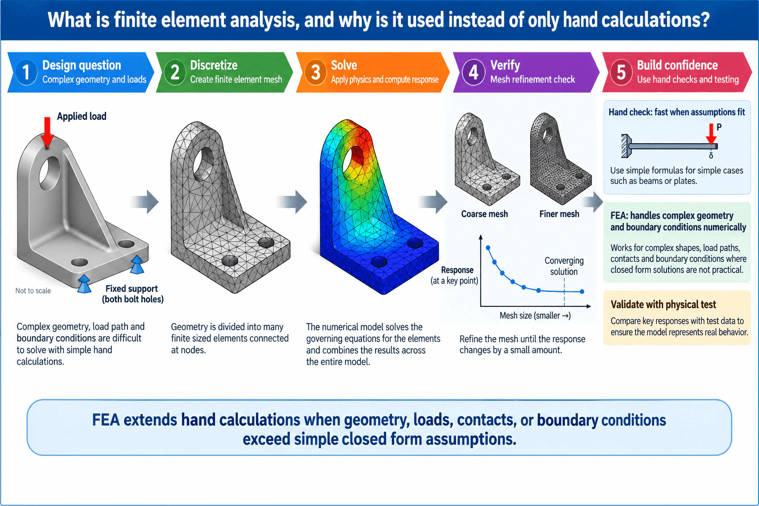
Finite element analysis, or FEA, is a numerical method that divides complex geometry into many finite elements connected at nodes and solves the governing equations across that discretized model. Hand calculations are still valuable for simple cases because they are fast and transparent, but closed form solutions depend on simplifying assumptions. FEA becomes useful when geometry, load paths, contacts, or boundary conditions are too complex for those assumptions. I would still check the model with mesh convergence, suitable hand calculations, and test evidence when available.
Detailed Explanation
Finite element analysis is a numerical method for solving engineering problems that are difficult to represent with one simple closed form equation. Instead of treating a component as one idealized shape, FEA divides its geometry into many finite sized elements connected at nodes. The solver applies the selected governing physics, material behavior, loads, supports, contacts, and other boundary conditions to that discretized model and calculates the response throughout the structure.
Hand calculations remain important. For a simple beam, plate, or another case that matches known assumptions, a hand calculation can provide a fast, transparent estimate. The limitation is that real components can have curved geometry, changing sections, complicated load paths, contacts, multiple constraints, and local effects that simple formulas do not represent well.
Useful Questions to Ask the Interviewer
Is the goal a quick engineering estimate, a local stress assessment, or a higher fidelity design decision?
Which loads, supports, contacts, and material assumptions should the model represent?
Is there analytical or physical test evidence available for comparison?
How to Explain It in an Interview
I would explain FEA as five connected steps.
Define the design question. Identify the physical geometry, applied loads, supports, contacts, material behavior, and the accuracy needed for the decision. The boundary conditions should represent the real system as closely as the purpose of the model requires.
Discretize the geometry. Divide the component into finite elements connected at nodes. The mesh converts a continuous body into a numerical model that the solver can evaluate.
Solve numerically. The solver assembles and solves the governing equations for the elements and combines their behavior across the model. Depending on the analysis, results can include displacement, strain, stress, temperature, or other physical responses.
Verify the numerical solution. Refine the mesh from a coarser mesh to a finer mesh and monitor a meaningful response at a defined location or region. If that response approaches a stable value, confidence in mesh convergence increases. I would also investigate singularities, rigid body modes, and sensitivity to important assumptions when relevant.
Build confidence with independent evidence. For portions of the problem that can be simplified appropriately, compare the FEA response with a hand calculation. When physical test data is available, compare important predicted and measured responses. Mesh convergence checks the numerical solution, while test correlation helps determine whether the model represents physical behavior.
The key point is that FEA does not replace hand calculations. It extends them when geometry, loads, contacts, or boundary conditions exceed simple closed form assumptions. A colorful contour or a converged mesh alone is not proof that the physical model is correct.
Why Interviewers Ask This
Interviewers want to see whether the candidate understands what finite element analysis does, why numerical analysis is useful when simple analytical assumptions no longer represent the geometry or load path well, and how an engineer verifies and validates a model instead of trusting a stress contour alone.
Common interview mistakes
Common mistakes include treating the stress contour as proof that the model is correct, applying unrealistic loads or supports, using a mesh without checking convergence, interpreting a mathematical singularity as a meaningful physical stress without investigation, overlooking rigid body modes, choosing unnecessary model complexity, and failing to compare important responses with independent analytical or test evidence.
Interview tip
Keep the explanation centered on why FEA complements hand calculations. Explain discretization simply, connect FEA to complex geometry and boundary conditions, and distinguish numerical verification such as mesh convergence from physical validation such as test correlation.
Interviewer may ask next
How would you check whether an FEA result is trustworthy?
I would first check whether the loads, supports, contacts, material assumptions, and solver physics represent the intended physical problem. Then I would inspect equilibrium where applicable, rigid body modes, singular behavior, mesh convergence, and sensitivity to important assumptions. I would also compare suitable responses with hand calculations and, when available, physical test data. Mesh convergence alone shows numerical stability with refinement, not that the physical model itself is correct.
What would change if the geometry were simple and the loading matched a standard beam case?
I would start with the hand calculation because it is faster, transparent, and directly tied to known assumptions. FEA may still be useful if I need local detail, want to study geometry changes, or need to connect the simple region to a more complex assembly. In that situation, the analytical result can also serve as an independent check on the numerical model.
22. What is the difference between a node and an element in FEA?Simulation And Engineering AnalysisEasy
i Question Details
Define nodes as solution locations and elements as connected interpolation regions that collectively represent the model.
Short Interview Answer (30-60 seconds)
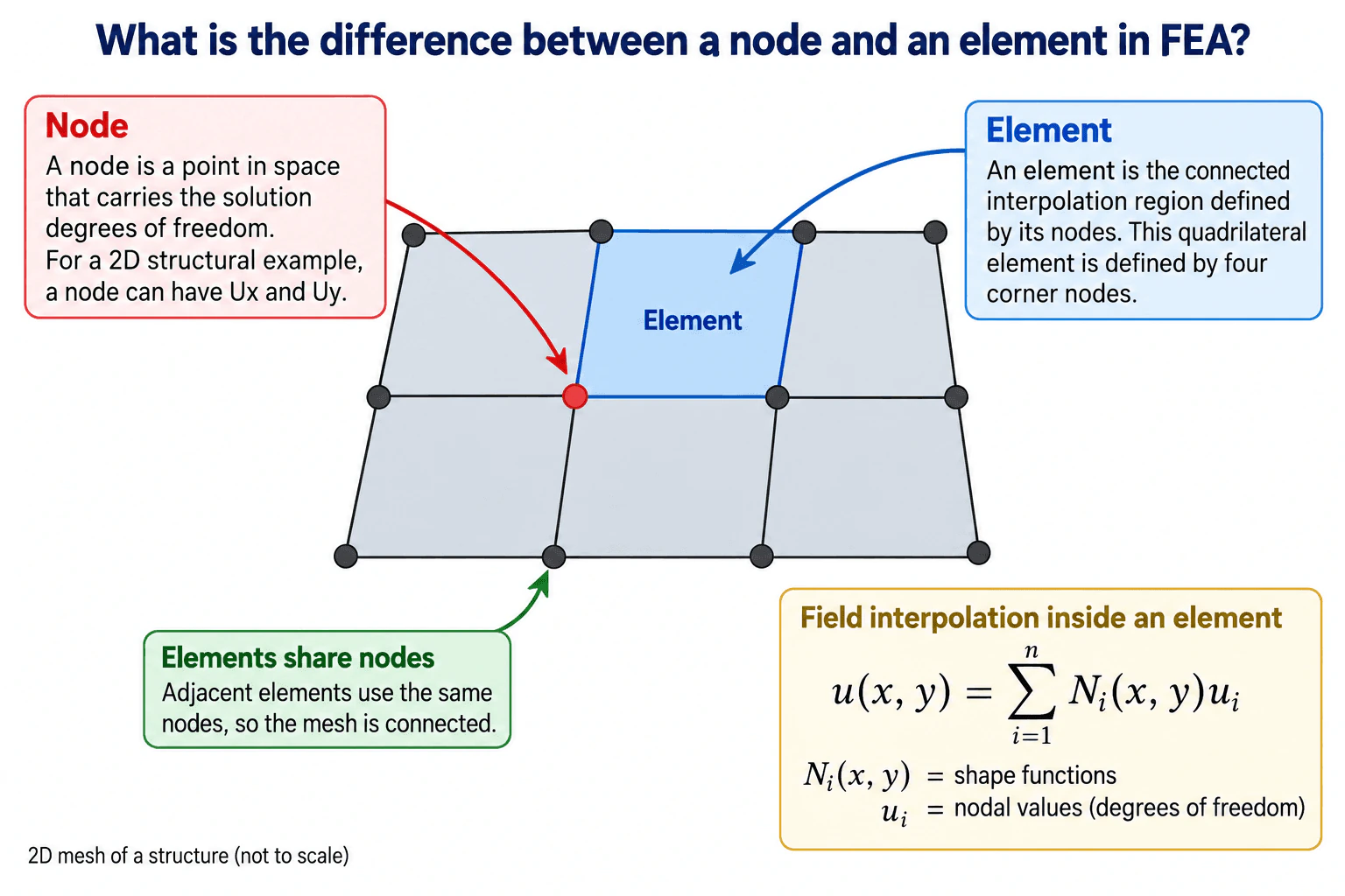
A node is a discrete location in the finite element mesh where solution degrees of freedom are defined. In a simple two dimensional structural example, a node can have displacement components Ux and Uy. An element is a connected interpolation region defined by a set of nodes. The element uses shape functions to interpolate the field between its nodal values. Adjacent elements can share nodes, and together the nodes and elements form the finite element mesh.
Detailed Explanation
A node and an element have different roles in finite element analysis. A node is a discrete solution location. An element is a finite interpolation region connected by nodes.
Useful Questions to Ask the Interviewer
Are we discussing structural FEA or another type of analysis such as thermal FEA?
Should I use a specific element type, such as a four node quadrilateral, as the example?
Would you like me to explain how shape functions interpolate nodal values inside an element?
How to Explain It in an Interview
Node
A node is a point in the mesh where solution degrees of freedom are defined. In a simple two dimensional structural model, a node can have displacement components Ux and Uy. The actual degrees of freedom depend on the physics and element formulation.
Element
An element is the connected interpolation region defined by a group of nodes. For example, a four node quadrilateral element is defined by four corner nodes. The element uses its shape functions to approximate the field inside that region from the nodal values.
For a field variable u, the interpolation can be written conceptually as
u(x, y) = Σ Nᵢ(x, y)uᵢ
where Nᵢ(x, y) are the shape functions and uᵢ are the nodal values.
How They Work Together
Adjacent elements can share the same nodes. Those shared nodes connect the mesh and allow the assembled finite element model to represent the physical domain as a collection of connected interpolation regions.
A useful interview summary is: nodes are solution locations, while elements are connected regions that use the nodal values to interpolate the solution between those locations.
This distinction is important when creating or reviewing a mesh because nodes identify where the solver carries discrete unknowns, while the element definition controls how the solution is represented within each region.
Why Interviewers Ask This
Interviewers want to confirm that the candidate understands the basic discretization concept behind finite element analysis. A strong answer distinguishes the locations where solution degrees of freedom are defined from the connected regions that use those nodal values to interpolate the solution.
Common interview mistakes
Common mistakes include describing a node as a small physical piece of material, treating every element as only a line between two nodes, or assuming that every node always has the same degrees of freedom. Another mistake is confusing the solution location with the interpolation region. A node carries discrete solution variables, while an element connects nodes and defines how those values are interpolated within the element.
Interview tip
Start with the simplest distinction: a node is a solution location, while an element is a connected interpolation region. Then use a four node quadrilateral example, mention shared nodes, and explain that shape functions interpolate nodal values inside the element. That directly answers the question without expanding into the full FEA workflow.
Interviewer may ask next
How would you check whether the mesh is sufficiently refined?
I would perform a mesh convergence study using a result that matters to the engineering decision, such as displacement, strain energy, or a physically meaningful stress away from a singularity. I would refine the mesh and compare the result between successive meshes. I would also check that the boundary conditions, contacts, material model, and element formulation represent the intended physical problem.
What changes when a higher order element is used?
A higher order element uses higher order interpolation and commonly includes additional nodes. This can represent curved geometry and changing field values more accurately within an element, but it also increases the number of degrees of freedom and computational cost. The appropriate choice depends on the geometry, solution gradients, required accuracy, and demonstrated convergence.
23. How would you determine whether a high local FEA stress is a real design concern or a singularity?Simulation And Engineering AnalysisHard
i Question Details
Check mesh dependence, geometric idealization, load or constraint application, physical notch radius and whether the quantity of interest converges to a finite value.
Short Interview Answer (30-60 seconds)
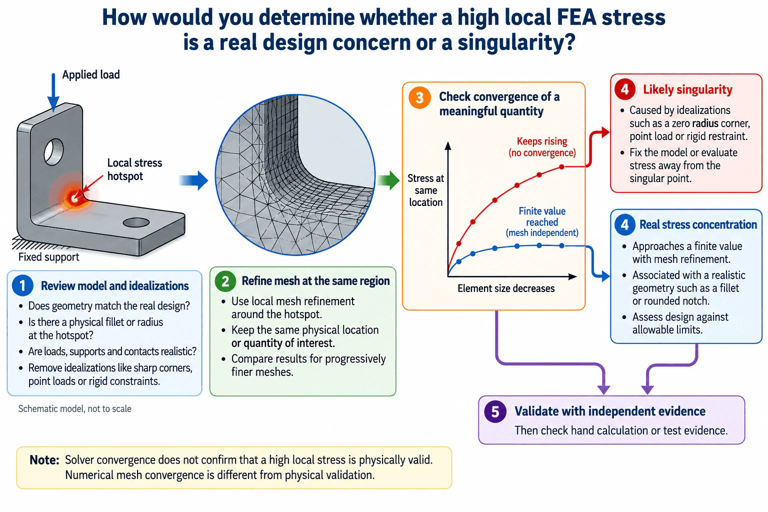
I would first inspect the geometry, loads, supports, contacts, and the local feature where the peak occurs. Then I would refine the mesh around the same region and track the same meaningful stress quantity at a consistent physical location. If the stress keeps increasing as element size decreases, especially at a zero radius corner, point load, or rigid restraint, I would suspect a singularity. If it approaches a finite value and the geometry represents the real fillet or notch, I would treat it as a potentially real stress concentration. I would still validate the result with a hand calculation, sensitivity study, or test evidence before making a design decision.
Detailed Explanation
A high local FEA stress is not automatically a design failure. The main question is whether the result represents a physical stress concentration that approaches a finite value, or a mathematical singularity caused by the model idealization.
Useful Questions to Ask the Interviewer
Does the real part have a physical fillet or notch radius at the reported hotspot?
How are the load and support applied, and do they represent the real load path?
Which stress quantity or structural response is being used for the design decision?
How to Explain It in an Interview
I would start by reviewing the model around the hotspot. I would check whether the geometry matches the real part, whether a physical fillet or radius was removed, and whether the loads, supports, contacts, and restraints represent reality. Zero radius corners, point loads, and rigid restraints can create singular behavior. I would also confirm that the model has no unintended rigid body motion.
Next, I would refine the mesh locally around the same region while keeping the geometry, loading, constraints, material model, and result definition consistent. I would compare the same meaningful quantity at the same physical location, or with the same evaluation method, as element size decreases.
If the local stress keeps rising without approaching a finite value, I would suspect a singularity. I would then revisit the idealization. For example, I could include the real fillet radius, distribute a concentrated load over its actual contact area, or replace an unrealistically rigid restraint with a more representative boundary condition. If the physical problem genuinely contains a singular point, I would not use the peak stress exactly at that point as the acceptance metric. I would evaluate an appropriate quantity away from the singular location.
If the stress approaches a stable finite value with mesh refinement and the local geometry and boundary conditions are realistic, I would treat it as a real stress concentration that could govern the design. I would compare that converged quantity with the applicable design criterion and consider whether material or contact nonlinearities are relevant.
I would separate numerical verification from physical validation. Mesh convergence shows that the numerical result is becoming stable for the selected model. It does not prove that the model represents the real structure. I would therefore use a hand calculation, sensitivity analysis, or test evidence to check the load path and the order of magnitude of the response.
My final decision would be based on convergence behavior, physical realism, sensitivity to assumptions, and independent evidence, not simply the highest value shown on a stress contour.
Why Interviewers Ask This
Interviewers want to see whether I can distinguish a physically meaningful stress concentration from a numerical singularity instead of accepting the peak value from a stress contour. They are evaluating judgment around mesh convergence, geometric idealization, boundary conditions, load application, physical notch radius, sensitivity analysis, and independent validation.
Common interview mistakes
Common mistakes include accepting the maximum contour value without checking mesh dependence, refining the mesh but comparing different physical locations, ignoring a missing physical radius, applying an unrealistic point load or rigid support, assuming solver convergence proves physical correctness, and dismissing every high stress near a sharp feature as harmless without checking the real geometry and load path.
Interview tip
Organize the answer around three checks: whether the model is physically realistic, whether the quantity of interest approaches a finite value under local mesh refinement, and whether the conclusion is supported by independent evidence. Explicitly separate numerical verification from physical validation.
Interviewer may ask next
What would you do if the peak stress keeps increasing with mesh refinement but the feature must remain geometrically sharp in the model?
I would first determine whether the sharp feature is physically sharp or only a modeling idealization. If it is an idealization, I would represent the real radius or contact geometry. If the physical problem genuinely contains a singular point, I would not use the stress exactly at that point as the design metric. I would evaluate an appropriate response away from the singular location, such as stress at a specified distance, section force, displacement, or another quantity suited to the failure mode. I would also check sensitivity to the boundary conditions and validate the broader response with hand calculations or test evidence.
How would your approach change if adding the real fillet radius causes the stress to converge to a high but finite value?
That would shift the concern from a likely mathematical singularity to a physically meaningful stress concentration. I would verify that the radius, load path, material model, contacts, supports, and mesh resolution are representative. I would then compare the converged quantity with the applicable design criterion and determine whether local yielding, fatigue, contact behavior, or another nonlinear effect needs to be considered. I would still support the decision with sensitivity studies, hand calculations, or test correlation rather than relying on FEA alone.
24. What is a functional requirement in mechanical design?Mechanical DesignEasy
Short Interview Answer (30-60 seconds)
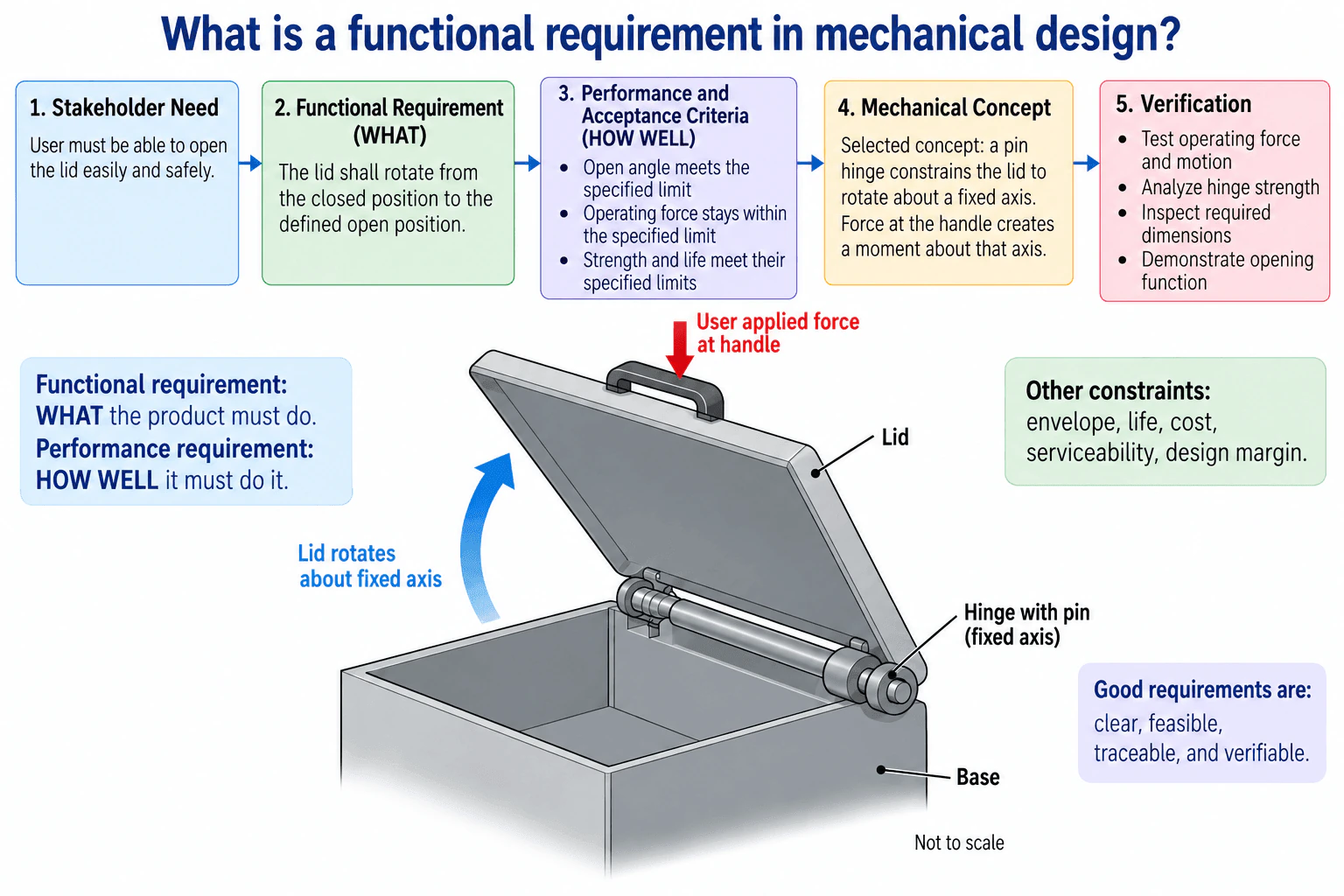
A functional requirement states what a mechanical product must do without prescribing the physical solution too early. For example, a lid requirement could state that the lid shall rotate from the closed position to the defined open position. Performance requirements then define how well it must do that, such as limits for open angle, operating force, strength, and life. The engineer then selects a concept, such as a pin hinge, while also considering envelope, loads, cost, serviceability, durability, and design margin, and verifies each requirement with appropriate evidence.
Detailed Explanation
A functional requirement describes the required behavior of a mechanical product. It answers WHAT the product must do. It should normally remain independent of the selected hardware so that multiple concepts can be considered before a design is chosen.
For a hypothetical hinged lid, the stakeholder need might be that the user can open the lid easily and safely. A suitable functional requirement is: the lid shall rotate from the closed position to the defined open position. That statement defines the required function without requiring a particular hinge design.
Performance requirements then answer HOW WELL the function must be performed. They should use measurable acceptance criteria. For the lid, those criteria could state that the open angle must meet its specified limit, operating force must stay within its specified limit, and strength and life must meet their specified limits. The actual numerical limits would come from the product requirements and should not be invented.
The engineer also captures constraints and assumptions. These can include the available envelope, expected loads, required life, cost target, serviceability needs, tolerance effects, durability, uncertainty, and design margin. These constraints influence concept selection even though they are not the functional requirement itself.
After the requirements are defined, concepts can be compared using traceable criteria. One selected concept might use a pin hinge that constrains the lid to rotate about a fixed axis. A user force applied at the handle creates a moment about that axis. The hinge, lid, base, and their interfaces must then be designed so the chosen concept satisfies the functional and performance requirements within the stated constraints.
Verification closes the traceability loop. Operating force and motion can be checked by test, hinge strength by analysis, required dimensions by inspection, and the opening function by demonstration. The important principle is that every requirement should have clear evidence showing whether it has been satisfied.
Useful Questions to Ask the Interviewer
Is the physical concept already fixed, or should the functional requirement remain solution neutral?
Which measurable acceptance criteria matter most, such as open angle, operating force, strength, or life?
Which constraints are fixed, such as envelope, load, cost, or serviceability?
How to Explain It in an Interview
I would start by separating the function from the solution. A functional requirement says what the product must do, while the selected mechanical concept describes how it will do it.
For example, for a lid I would write the functional requirement as: the lid shall rotate from the closed position to the defined open position. I would not write that a pin hinge must perform the function unless the hinge concept had already been mandated.
Next, I would define measurable performance requirements. These could cover the required open angle, maximum operating force, required strength, and required life. I would also capture constraints such as available envelope, expected loads, cost, serviceability, tolerance, durability, and design margin.
Then I would compare possible concepts against those traceable requirements. If a pin hinge were selected, I would describe it as the implementation. The hinge constrains the lid to rotate about a fixed axis, and force applied at the handle creates a moment about that axis.
Finally, I would connect each requirement to verification evidence. Motion and operating force could be tested, hinge strength could be analyzed, required dimensions could be inspected, and the opening function could be demonstrated. That trace from stakeholder need to function, measurable criteria, concept, and verification is what makes the requirement useful in mechanical design.
Why Interviewers Ask This
Interviewers want to know whether you can separate the function a product must perform from the physical concept used to perform it. They are also evaluating whether you can translate a stakeholder need into traceable requirements, measurable acceptance criteria, design constraints, concept decisions, and verification evidence.
Interviewer may ask next
How would you check whether a functional requirement is well written?
I would check that it states a required function rather than a preferred solution, traces back to a stakeholder need, avoids invented design details, and connects to measurable performance requirements. I would also confirm that there is a practical verification method, such as test, analysis, inspection, or demonstration, so the requirement can be judged objectively.
What changes if the available packaging envelope becomes much smaller?
The basic function can remain the same, but the constraint set becomes tighter. I would reassess concept selection because the existing hinge geometry, handle position, motion path, service access, or assembly approach might no longer fit. I would compare alternative concepts against the same functional requirement while reconsidering operating force, strength, life, manufacturability, cost, tolerance, and serviceability before selecting the revised design.
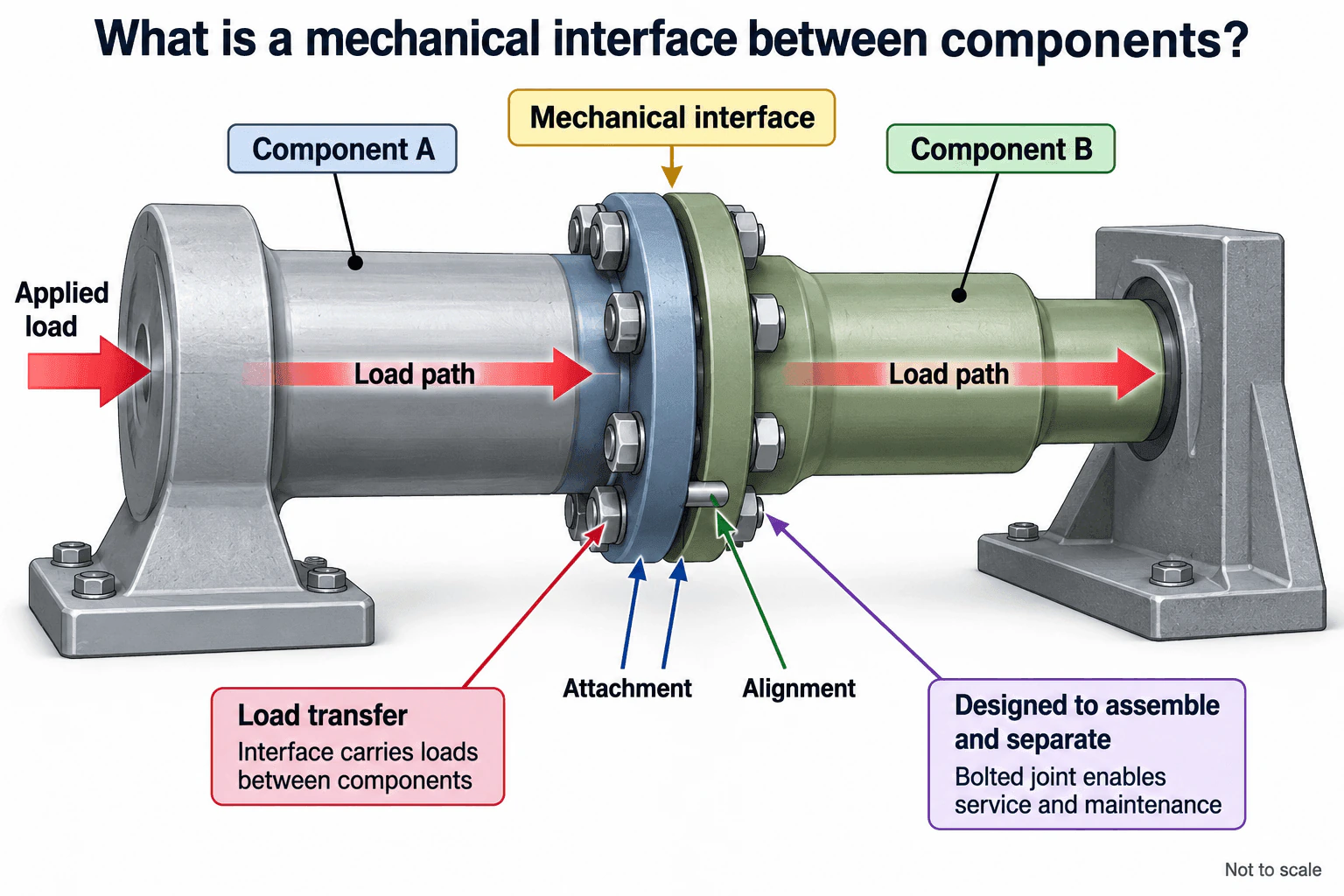
25. What is a mechanical interface between components?Mechanical DesignEasy
Short Interview Answer (30-60 seconds)
A mechanical interface is the physical connection and interaction boundary between two components. It defines how they attach, align, transfer loads or motion, fit together, and can be assembled or serviced. In the illustrated example, Component A and Component B meet at a bolted flange interface. The joint provides attachment, supports the required alignment, transfers the applied load between the components, and can be separated for service or maintenance.
Detailed Explanation
A mechanical interface is the physical boundary where two components connect and interact. It includes the mating surfaces, joint features, locating features when required, fasteners, fits, clearances, and other details that determine how the components work together.
In the illustrated example, Component A and Component B meet at a bolted flange interface. The bolts provide attachment. The interface must also provide or support the required alignment between the components. The illustrated load path shows an applied load passing from Component A through the interface into Component B. Because the joint is bolted, the components can also be assembled and separated for service or maintenance.
The exact interface design depends on measurable requirements such as loads, allowed motion, alignment, available envelope, design life, cost, tolerances, assembly access, serviceability, and acceptance criteria. The diagram identifies alignment as an interface function, but it does not specify the exact locating feature, so that detail would need to be defined from the actual design requirements.
Useful Questions to Ask the Interviewer
What loads and relative motions must the interface support or prevent?
What alignment, envelope, life, and tolerance requirements apply at the connection?
Does the interface need to be removable for assembly, inspection, or service?
How to Explain It in an Interview
Engineering Method
I would first define what the interface must accomplish. For this flange example, that means attaching Component A to Component B, providing the required relative alignment, transferring the specified service loads, fitting within the available envelope, meeting the required life, and allowing service access if disassembly is required.
I would then select an interface concept that satisfies those requirements. A bolted flange is one option when a removable connection is useful. The bolts provide attachment, while suitable mating or locating features provide the required positional control. I would not assume the flange contact alone provides precise alignment unless the geometry was specifically designed to do so.
Next, I would trace the load path. The external load shown on Component A must pass through the joint and continue into Component B. I would identify which joint features carry that load and verify that the assumed transfer mechanism is physically defined.
Design Reasoning
The interface has to balance several requirements. Tighter alignment can increase manufacturing and assembly sensitivity. A removable joint improves serviceability but adds fasteners and assembly operations. Tolerances must permit reliable assembly while still controlling component position. Durability, uncertainty, and appropriate design margins must also be considered for the actual operating conditions.
Assumptions And Checks
I would not invent dimensions, loads, tolerances, material properties, or margins. Those remain required inputs until specified. Verification would trace each interface requirement to an appropriate engineering check, such as confirming the load path, checking fit and alignment capability, reviewing assembly and service access, and confirming compatibility with the required life and operating conditions.
The key idea is that a mechanical interface defines how two components physically connect and function together, not simply where they touch.
Why Interviewers Ask This
Interviewers want to see whether the candidate understands that components interact through defined physical boundaries. A good answer should recognize attachment, alignment, load transfer, assembly, serviceability, tolerances, and the requirements that govern the connection.
Interviewer may ask next
How would you verify that a mechanical interface is acceptable before releasing the design?
I would trace each interface requirement to a verification method. I would confirm the intended load path, check that the attachment features can support the defined loads with the required design margin, verify that the chosen locating features and tolerances can achieve the required alignment, review assembly and service access, and confirm compatibility with the required life and operating conditions. Any loads, tolerances, material properties, or acceptance limits that are not defined would remain explicit unknowns.
How might the interface change if the connection had to be serviced frequently?
Frequent service would make accessibility, repeatable alignment, removal time, and protection against assembly errors more important. A removable bolted interface could be appropriate if it still satisfies the structural requirements. I would also consider fastener access, locating features that restore alignment after reassembly, wear at repeated contact surfaces, replacement of damaged hardware, and whether the additional serviceability justifies any increase in parts, envelope, cost, or assembly effort.
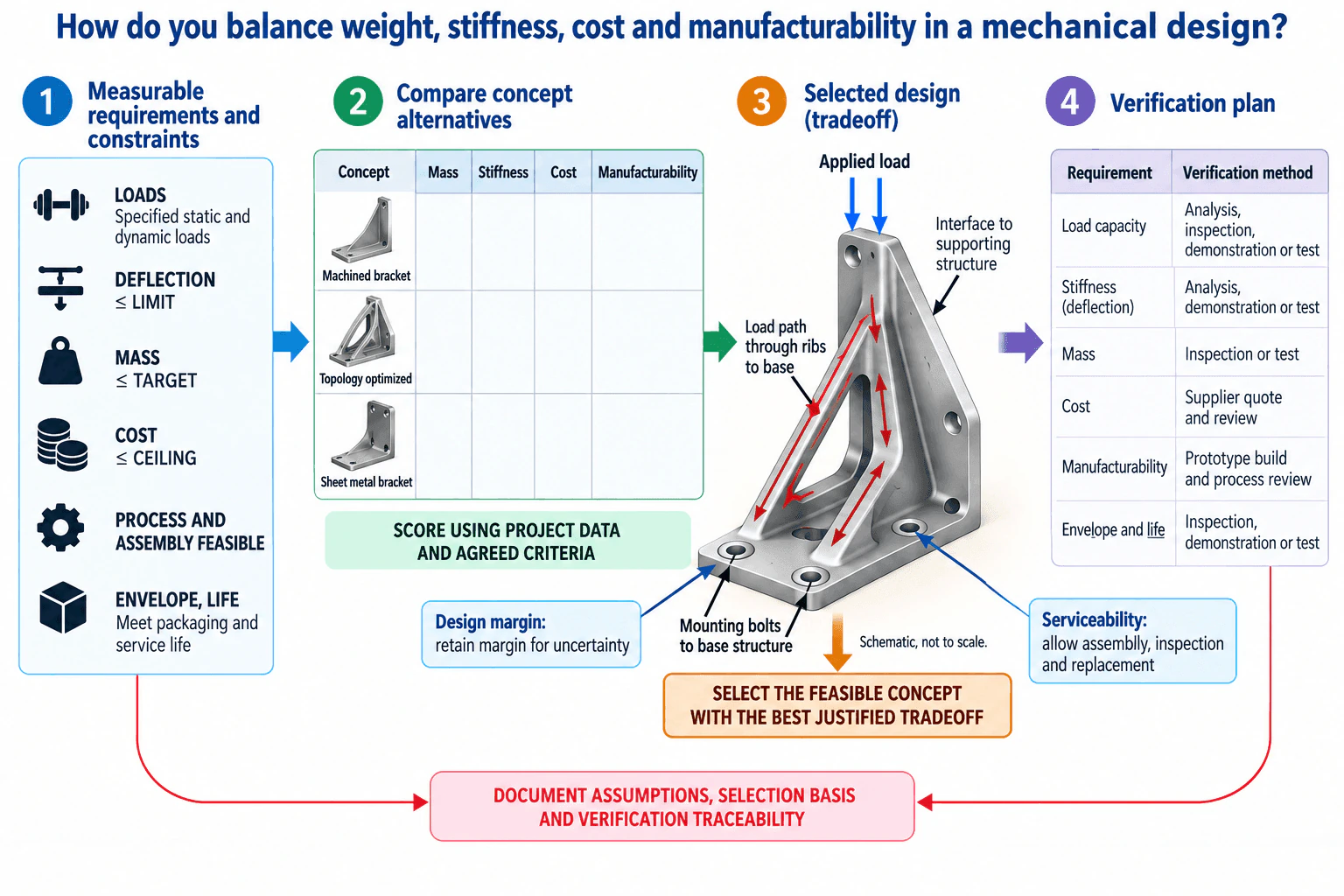
26. How do you balance weight, stiffness, cost and manufacturability in a mechanical design?Mechanical DesignMedium
i Question Details
Convert each objective into a measurable constraint or trade metric, compare alternatives and document the selected compromise and its validation plan.
Short Interview Answer (30-60 seconds)
I start by converting the objectives into measurable requirements such as allowable deflection, mass target, cost ceiling, required loads, package envelope, service life, and feasible manufacturing and assembly processes. I then compare viable concepts against the same agreed criteria using project data. After selecting the feasible concept with the best justified tradeoff, I check interfaces, load paths, serviceability, uncertainty, and design margin. Finally, I maintain requirements traceability and define verification by analysis, inspection, demonstration, or test as appropriate.
Detailed Explanation
Balancing weight, stiffness, cost and manufacturability is not about maximizing one attribute. It is about finding a feasible design that satisfies the important requirements while making the best justified compromise among competing objectives. I would keep the decision traceable from the original requirements through concept selection and verification.
Useful Questions to Ask the Interviewer
What loads, deflection limits, package constraints, service life, and interfaces are fixed?
Are there explicit mass and cost targets, and which requirements are mandatory versus preferred?
What manufacturing processes, production volumes, assembly constraints, and service requirements should I assume?
How to Explain It in an Interview
Engineering Method
First, I translate each objective into a measurable acceptance criterion where possible. Mass must be at or below its target, deflection must be at or below its limit, cost must remain within its ceiling, and the manufacturing and assembly approach must be feasible. I also capture applied loads, envelope, required life, interfaces, and operating assumptions.
Next, I generate several viable concepts, such as a machined bracket, a topology optimized form, or a sheet metal bracket. I evaluate every concept against the same criteria: mass, stiffness, cost, and manufacturability. I do not assume that one process is always lighter, cheaper, stiffer, or easier to manufacture. The comparison should use project data and agreed criteria, supported by calculations, estimates, supplier input, or prototype evidence as appropriate.
I then select the feasible concept with the best justified tradeoff. For the selected ribbed bracket, I examine how the applied load travels through the ribs into the base and mounting interfaces. I also review assembly access, inspection, replacement, tolerance sensitivity, durability, uncertainty, and design margin.
Assumptions And Checks
I separate known requirements from assumptions and unknowns. I check that loads and interfaces are complete, the concept fits the available envelope, and the manufacturing process can produce and assemble the geometry. I also check whether uncertainty in loads, tolerances, material behavior, cost, or process capability could change the selection.
Design Reasoning
Each important requirement should remain traceable to a verification method. Load capacity and stiffness may use analysis, inspection, demonstration, or test depending on the requirement. Mass can be verified by inspection or weighing. Cost can be supported by supplier quotes and review. Manufacturability can be checked through prototype builds and process review. Envelope and life requirements can use inspection, analysis, demonstration, or test as appropriate.
I would document the assumptions, selection basis, unresolved risks, and verification traceability. If later evidence changes an important constraint, I would revisit the concept comparison rather than defend the original selection by default.
Why Interviewers Ask This
Interviewers want to see whether you can convert competing objectives into measurable requirements, compare concepts using traceable evidence rather than assumptions, select a defensible compromise, integrate interfaces and load paths, and define how the chosen design will be verified.
Interviewer may ask next
How would you validate that your selected concept is still the right choice before release?
I would trace every critical requirement to evidence and verify the assumptions that drove the concept selection. I would review the actual load cases, interfaces, tolerances, manufacturing capability, assembly access, cost evidence, service conditions, uncertainty, and design margin. Verification could include analysis, inspection, demonstration, or physical testing depending on the requirement. If new evidence shows that an assumption is wrong or a requirement is not met, I would update the concept comparison and reconsider the selection rather than simply adding material or accepting the discrepancy.
What would you do if the mass target became much more aggressive after the concept was selected?
I would first confirm whether the new mass target is mandatory and identify which requirements cannot be relaxed, especially stiffness, load capacity, envelope, life, cost, and manufacturability. Then I would revisit the concept comparison using the new constraint. Possible actions could include changing geometry, improving the load path, removing low value material, reconsidering the manufacturing process, or evaluating another concept. I would compare those options using updated project data and confirm that any mass reduction does not create unacceptable deflection, durability, assembly, cost, serviceability, or design margin problems.
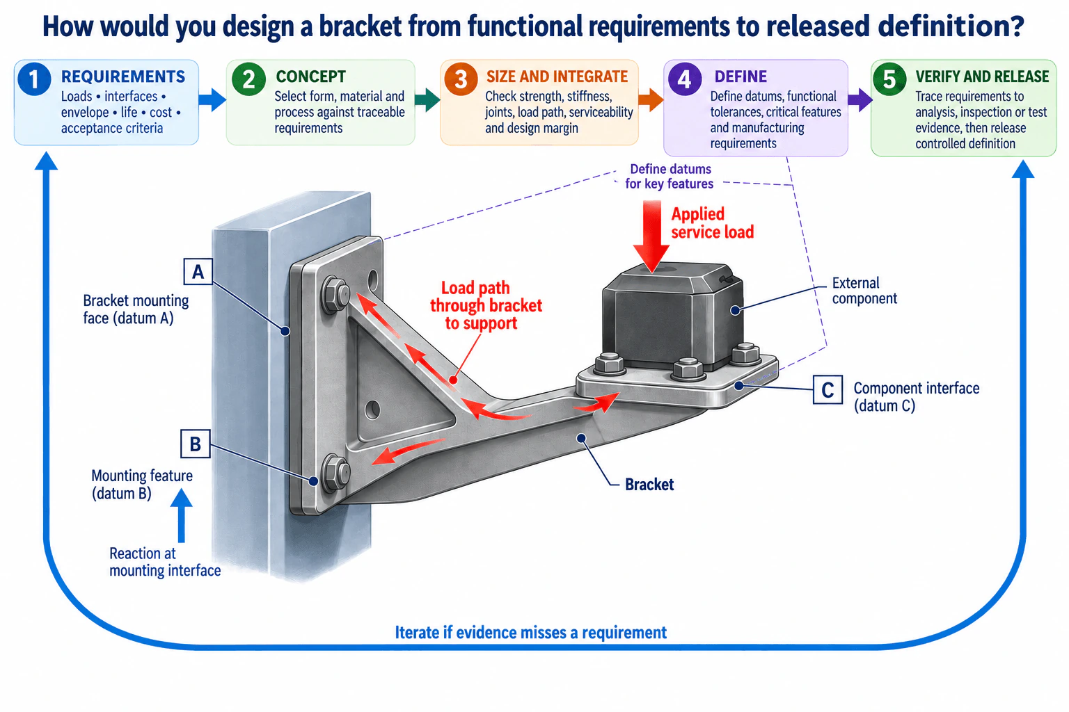
27. How would you design a bracket from functional requirements to released definition?Mechanical DesignMedium
i Question Details
Define loads, interfaces and envelope; choose material and process; size strength and stiffness; set datums and tolerances; verify manufacturability and define validation evidence.
Short Interview Answer (30-60 seconds)
I would start by converting the functional need into measurable requirements for loads, interfaces, envelope, life, cost, and acceptance criteria. I would compare practical bracket concepts and select the form, material, and manufacturing process against those requirements. Then I would define the load path from the external component through the bracket to the mounting interface and supporting structure, and size the design for strength, stiffness, joints, serviceability, uncertainty, and appropriate design margin. Next I would establish functional datum features and tolerances from the actual interfaces. Finally, I would trace every requirement to analysis, inspection, or test evidence and release the controlled definition only when the evidence supports the requirements.
Detailed Explanation
I treat bracket design as a requirements traceability problem, not just a geometry problem. The bracket must carry the applied service load from the external component through the bracket to the mounting interface and supporting structure while satisfying interface, envelope, durability, manufacturing, assembly, serviceability, cost, and verification needs. The mounting interface provides the reaction that closes the load path. I would keep assumptions separate from known requirements and avoid inventing dimensions, loads, material properties, tolerances, or design margins before they are established.
Useful Questions to Ask the Interviewer
What load cases, directions, duty cycle, life, and environmental conditions must the bracket withstand?
Which mounting and component interfaces are fixed, and what envelope or assembly access constraints apply?
What manufacturing volume, process constraints, cost targets, and measurable acceptance criteria govern the design?
How to Explain It in an Interview
I would use five connected steps.
First, I define the requirements. I capture service loads, interfaces, available envelope, required life, cost targets, environmental conditions, assembly needs, and measurable acceptance criteria. I also identify unknowns and assumptions so they can be closed before release.
Second, I select the concept. I compare practical bracket forms, candidate materials, and manufacturing processes against the traceable requirements. The choice must support the required geometry, expected production method, assembly access, durability, and cost rather than optimizing strength alone.
Third, I size and integrate the bracket. I establish the physical load path from the external component, through the bracket, into the mounting interface and supporting structure. I check the governing strength and stiffness behavior, the mounting joints, local load transfer, serviceability, uncertainty, and design margin. I also check whether surrounding parts can be assembled, accessed, and serviced.
Fourth, I create the released definition around functional interfaces. A representative datum scheme can use the bracket mounting face as datum A, a mounting feature as datum B, and the component interface as datum C. The exact datum hierarchy depends on how the real assembly locates the bracket. I then assign only the dimensions and tolerances needed to control fit, location, orientation, function, manufacturing, and inspection.
Fifth, I verify and release. Every important requirement must trace to suitable evidence such as engineering analysis, inspection, or physical test. I check manufacturability and assembly before release and resolve open risks. If evidence misses a requirement, I return to the relevant design decision, revise it, and repeat verification. The final output is a controlled product definition supported by traceable evidence, not merely a CAD model that appears acceptable.
Why Interviewers Ask This
Interviewers want to see whether I can turn an incomplete functional need into a traceable mechanical definition. They are evaluating how I establish loads and interfaces, select a concept and manufacturing approach, reason about strength and stiffness, define functional datums and tolerances, account for serviceability and design margin, and connect verification evidence back to measurable requirements before release.
Interviewer may ask next
How would you validate the bracket if some load cases were uncertain?
I would identify which load inputs are uncertain, document the assumptions, and determine how sensitive the design is to those inputs. I would use justified bounding load cases where appropriate and keep the resulting uncertainty visible in the design margin. Before release, I would close the important uncertainties through better system data, representative measurement, analysis correlation, or physical validation. I would not claim the bracket is acceptable solely because one nominal analysis case passes.
What would change if production volume increased significantly?
I would revisit concept and process selection because a design optimized for low volume machining may not be appropriate at higher volume. I would compare processes based on achievable geometry, tooling investment, recurring cost, material utilization, tolerance capability, joining needs, assembly effort, inspection, and expected production quantity. Any process change would trigger a review of geometry, datum strategy, tolerances, load path, joints, durability, manufacturability, and verification evidence before the new definition was released.
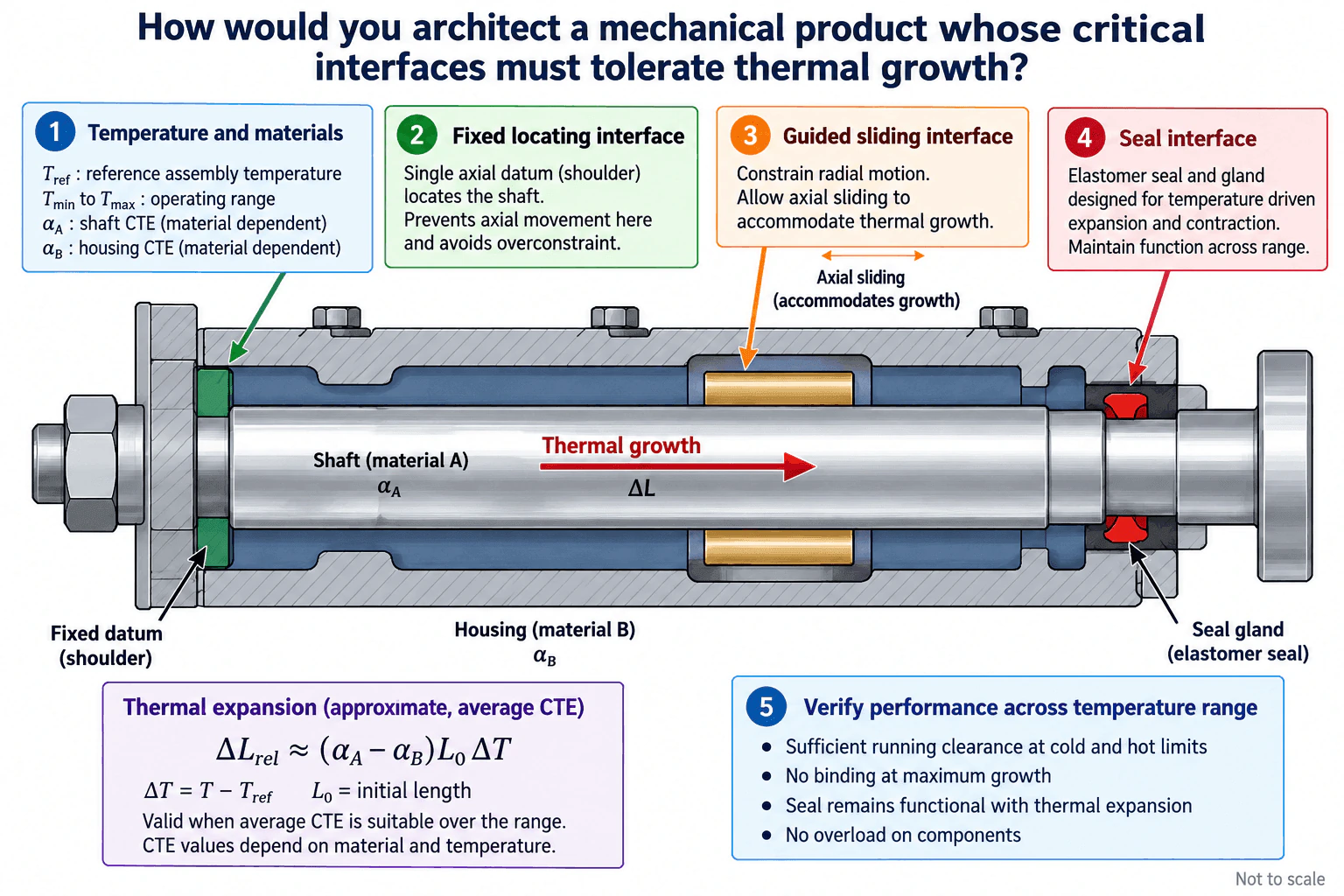
28. How would you architect a mechanical product whose critical interfaces must tolerate thermal growth?Mechanical DesignHard
i Question Details
Define temperature ranges, material CTEs, constraints, sliding or compliant interfaces, seals and clearances so thermal expansion does not create binding, leakage or overload.
Short Interview Answer (30-60 seconds)
I would define the reference assembly temperature, minimum and maximum operating temperatures, relevant interface lengths, and the CTE of each material. I would then establish one axial locating datum and avoid rigidly constraining thermal motion at both ends. The remaining support would maintain radial guidance while allowing the required axial sliding or compliant motion. I would size clearances and the seal interface for the cold and hot limits, including tolerances and uncertainty. For uniform temperatures, relative axial displacement can be estimated as ΔLrel ≈ (αA − αB)L0ΔT. I would finally verify adequate travel and clearance, seal function, and acceptable component loads throughout the operating range.
Detailed Explanation
Thermal growth should be treated as an interface architecture problem rather than only as an expansion calculation. The product needs a defined location, but it also needs a deliberate motion path for relative expansion. For the shaft and housing concept shown in the approved design, one interface establishes the axial datum, another guides the shaft radially while permitting axial sliding, and the seal gland maintains sealing while the assembly changes length.
Useful Questions to Ask the Interviewer
What are the reference assembly temperature, minimum operating temperature, and maximum operating temperature?
What materials, relevant interface lengths, loads, tolerances, sealing limits, and allowable clearances apply?
Which interface must establish the axial datum, and where is thermal motion allowed?
How to Explain It in an Interview
I would start by defining the requirements and assumptions. I would identify Tref, Tmin, Tmax, the relevant reference length L0, and material CTE values αA and αB. I would also define alignment, loads, life, serviceability, allowable leakage, minimum running clearance, available axial travel, envelope, and cost constraints. Unknown values stay explicit rather than being invented.
For a uniform temperature change and representative average CTE values, I would estimate relative axial displacement using ΔLrel ≈ (αA − αB)L0ΔT, with ΔT = T − Tref. The sign indicates which component grows farther relative to the other. If CTE changes materially with temperature or the temperature field is nonuniform, I would use temperature dependent properties and the actual thermal distribution instead of relying on one average value.
Next I would define the constraint architecture. I would use a single axial locating feature, such as the shoulder shown in the diagram, so the shaft has a known datum. I would not rigidly locate the shaft axially at both ends because restrained thermal expansion can create large internal loads. The guided interface would constrain radial motion while allowing enough axial travel for the calculated relative displacement plus tolerance and uncertainty.
I would then evaluate clearances separately because radial interference depends on the local diameters, material expansion, temperature, and tolerance stack. I would check the minimum running clearance at both cold and hot limits rather than assuming axial expansion alone proves freedom from binding.
The seal gland would be designed so the elastomer remains functional as the shaft and housing expand and contract. I would verify that thermal motion does not consume the available seal accommodation or create unacceptable leakage or load.
Finally, I would verify the complete tolerance and thermal stack against measurable acceptance criteria: sufficient running clearance, adequate sliding travel, no binding, acceptable component loads, and maintained seal function throughout the required temperature range.
Why Interviewers Ask This
This tests whether I can translate operating temperature, material expansion, mechanical constraints, clearances, sliding interfaces, sealing, tolerances, and verification criteria into one integrated product architecture that avoids binding, leakage, and excessive load.
Interviewer may ask next
How would you handle uncertainty in temperature, CTE, and manufacturing tolerances?
I would treat them as bounded design inputs and evaluate combinations that maximize relative growth, minimize running clearance, or maximize interface load. I would use temperature dependent material data when necessary and include dimensional tolerance, assembly variation, and temperature uncertainty in the stack. The design margin would be based on measurable criteria such as minimum clearance, remaining axial travel, seal accommodation, and maximum allowable component load rather than on an invented safety factor.
What would you do if axial sliding were not permitted?
I would replace the sliding degree of freedom with a compliant interface that can absorb the required relative displacement while maintaining alignment and load transfer. I would compare concepts using required motion, stiffness, fatigue life, packaging, seal compatibility, serviceability, manufacturing complexity, and cost. I would still keep one clear locating strategy and verify that the compliant feature has enough motion capacity and design margin to prevent binding, leakage, or overload throughout the specified temperature range.
29. What is the difference between verification and validation?Testing And ValidationEasy
i Question Details
Distinguish proving that a stated requirement was met from proving that the product satisfies the intended user need in real conditions.
Short Interview Answer (30-60 seconds)
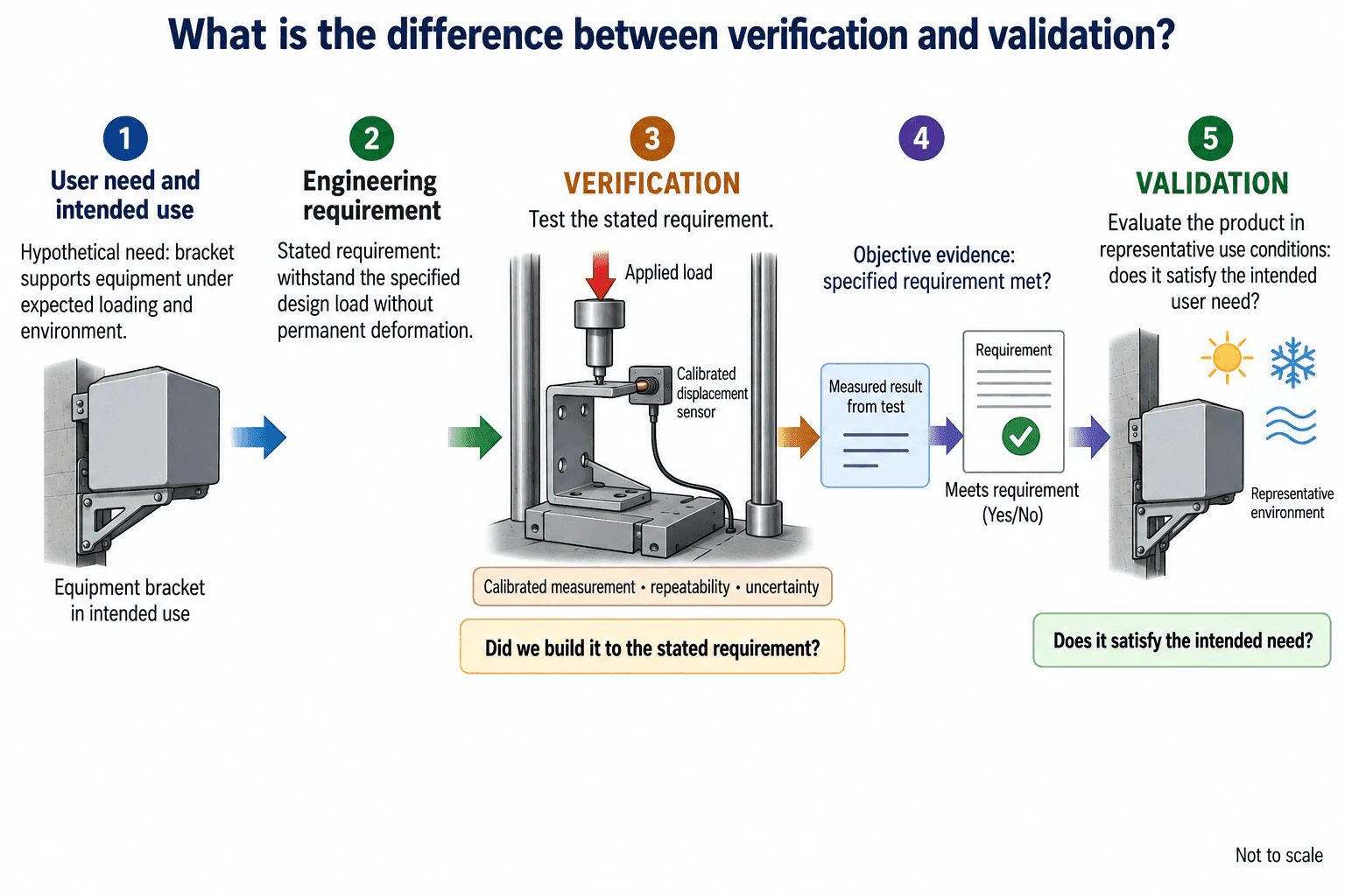
Verification asks whether the product meets its stated engineering requirements. I would trace the requirement to an operating condition, test method, calibrated measurement, and acceptance criterion, then use objective evidence to determine whether the requirement is met. Validation asks whether the product actually satisfies the intended user need in representative use conditions. In simple terms, verification checks the stated requirement, while validation checks the intended need.
Detailed Explanation
Verification and validation answer different questions. Verification demonstrates that a specified engineering requirement was met using objective evidence. Validation demonstrates that the product satisfies its intended user need under representative use conditions.
Useful Questions to Ask the Interviewer
What stated requirement and acceptance criterion should the verification test address?
What operating conditions are considered representative of the intended use?
What measurement uncertainty and repeatability expectations apply to the test?
How to Explain It in an Interview
Engineering Method
I would begin with the intended user need, then translate that need into a measurable engineering requirement. Using the diagram example, the hypothetical need is for a bracket to support equipment under expected loading and environmental conditions. A corresponding stated requirement is that the bracket withstand the specified design load without permanent deformation.
For verification, I would test that stated requirement. I would define the fixture, applied load direction, measurement location, sensor range, calibration status, sampling approach, and acceptance criterion before testing. If displacement is the relevant response, I would use an appropriate calibrated displacement sensor. I would also consider repeatability and measurement uncertainty so the measured result can support a defensible requirement decision.
The verification flow is therefore stated requirement, controlled test, measured result, then objective evidence compared with the acceptance criterion. The conclusion is whether the specified requirement was met.
For validation, I would evaluate the product under conditions representative of its intended use. The focus changes from compliance with the written requirement to whether the product actually satisfies the user need. Representative loading, environment, interfaces, and operating conditions matter because a product can meet a requirement while still failing to satisfy the real need if the requirement or test conditions were incomplete.
Assumptions And Checks
The exact design load, dimensions, tolerance, sensor range, acceptance limit, sample count, and environmental conditions are not supplied, so I would not invent them. I would confirm that the fixture and loading reproduce the intended physical boundary conditions, that the sensor is calibrated for the measured quantity and range, that measurement uncertainty is appropriate relative to the acceptance criterion, and that repeatability is understood.
Design Reasoning
Verification and validation are complementary. Verification provides objective evidence that the stated requirement was met. Validation provides evidence that the product satisfies the intended user need in representative conditions. Passing verification does not automatically prove successful validation if the original requirement did not fully capture the real use case.
Why Interviewers Ask This
Interviewers want to see whether I can distinguish proving compliance with a stated engineering requirement from proving that the completed product satisfies the intended user need under representative operating conditions. They are also evaluating whether I understand traceable test evidence, calibration, repeatability, measurement uncertainty, operating conditions, and acceptance criteria.
Common interview mistakes
Common mistakes include treating verification and validation as interchangeable, testing without a traceable acceptance criterion, using an unsuitable or uncalibrated measurement system, ignoring repeatability or measurement uncertainty, validating only under convenient laboratory conditions instead of representative use conditions, and claiming that a product is validated simply because one stated requirement passed verification.
Interview tip
State the distinction first, then connect it to one mechanical example. Explain that verification compares objective test evidence with a stated requirement and acceptance criterion, while validation evaluates whether the product satisfies the intended need under representative conditions. Mention calibration, repeatability, and measurement uncertainty as supporting evidence rather than turning the answer into a generic testing checklist.
Interviewer may ask next
How would measurement uncertainty affect a verification decision near the acceptance limit?
I would not rely on the measured value alone. I would evaluate the measurement uncertainty relative to the acceptance criterion and apply the appropriate decision rule. If the uncertainty is large enough that the true value could reasonably fall on either side of the limit, I would not claim an unqualified pass. I would consider whether improved instrumentation, calibration, test control, repeated measurements, or a better test method could reduce the uncertainty.
What changes if the product passes verification but fails validation in representative use conditions?
That indicates that the stated requirements, assumptions, or test coverage may not fully represent the intended user need or actual operating conditions. I would document the evidence, compare the validation conditions with the original requirements and assumptions, and determine whether the requirement, loading case, environmental condition, interface, or acceptance criterion needs revision. Any revised requirement would then need appropriate verification before validation is repeated.
30. How do you build a validation plan from system requirements?Testing And ValidationMedium
i Question Details
Map requirements to methods, risk-based sample coverage, operating conditions, instrumentation, protocols and objective acceptance criteria before execution.
Short Interview Answer (30-60 seconds)
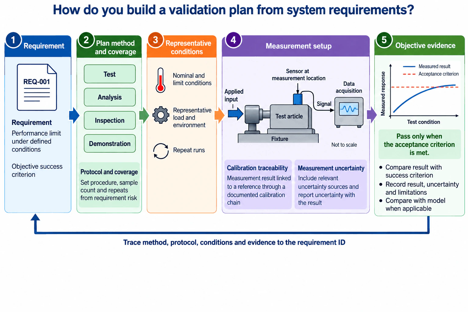
I start with each system requirement and define a measurable success criterion under its specified operating conditions. I assign the appropriate verification method, such as test, analysis, inspection, or demonstration, then define the protocol, sample coverage, representative loads, environmental conditions, and repeat runs based on requirement risk and expected variation. For physical testing, I select the fixture, sensor locations, measurement ranges, sampling, data acquisition, and calibration approach, and I plan for measurement uncertainty. Before execution, I define exactly how the result will be compared with the acceptance criterion and how the resulting evidence will trace back to the requirement ID.
Detailed Explanation
A good validation plan starts with traceability. I do not begin with a fixture or an available instrument. I begin with the requirement and define what objective evidence would demonstrate that the required performance has been achieved under the specified conditions. The plan then connects the requirement to the verification method, protocol, operating conditions, measurements, uncertainty, and acceptance decision.
Useful Questions to Ask the Interviewer
Which requirements are highest risk or most critical to validate?
What operating conditions and environmental limits must the validation represent?
Are there existing test facilities, instrumentation, models, or calibration constraints that the plan must use?
How to Explain It in an Interview
Engineering Method
First, I give each requirement a traceable identifier and convert its verification intent into an objective success criterion. I define the measured quantity, required limit, and operating condition before planning the test.
Next, I choose the verification method. Depending on the requirement, that may be test, analysis, inspection, or demonstration. I then define the protocol and coverage. Requirement risk, expected variation, and the consequence of an incorrect decision influence sample count, repeated runs, and the range of representative conditions.
For physical testing, I define the applied input, test article, fixture, sensor locations, and data acquisition path. Sensor range, resolution, sampling, and placement must suit the physical quantity being measured. Calibration records support traceability of the measurement result through a documented calibration chain. I also identify relevant uncertainty sources and plan how uncertainty will be reported with the result.
I include nominal and limiting conditions where appropriate, representative loading and environment, and repeat runs to evaluate repeatability rather than relying on one observation.
Finally, I define the acceptance decision before execution. I compare the measured result with the success or acceptance criterion, record uncertainty and limitations, and retain traceability to the requirement ID. When a predictive model is relevant, I compare the test result with the model prediction and investigate meaningful discrepancies instead of forcing agreement.
Assumptions And Checks
I confirm that the requirement is measurable, the selected method actually verifies it, the conditions represent intended use, and the instruments can resolve the required quantity. I also check that the method, protocol, conditions, result, uncertainty, and limitations remain traceable to the requirement.
Design Reasoning
The key principle is to define the evidence and acceptance logic before testing. A validation plan should produce defensible evidence, not merely data. A result is useful only when its operating condition, measurement traceability, uncertainty, and acceptance criterion are understood.
Why Interviewers Ask This
Interviewers want to see whether I can convert system requirements into objective, traceable verification evidence. They are evaluating how I select verification methods, define representative operating conditions, plan sample coverage and repeatability, choose suitable instrumentation, account for calibration and measurement uncertainty, and establish acceptance criteria before testing begins.
Common interview mistakes
Common mistakes include starting with available test equipment instead of the requirement, using vague acceptance language, failing to define representative operating conditions, choosing sample counts without considering risk and expected variation, ignoring repeatability, using sensors without checking range or calibration status, treating calibration as a substitute for uncertainty analysis, collecting data before defining the acceptance criterion, and failing to maintain traceability from the evidence back to the requirement.
Interview tip
Describe the plan as a traceable chain from requirement to verification method to protocol and operating conditions to measurement to acceptance evidence. Emphasize that acceptance criteria are defined before execution and that calibration, uncertainty, repeatability, sample coverage, and limitations are part of interpreting the result rather than afterthoughts.
Interviewer may ask next
How would you decide whether the sample coverage and number of repeat runs are sufficient?
I would base coverage on requirement criticality, expected variation, manufacturing variation, operating range, prior evidence, and the consequence of an incorrect acceptance decision. I would define which conditions must be represented, then choose enough samples and repeat runs to provide meaningful evidence about repeatability and variation. I would document the assumptions behind that choice rather than claim that one sample count applies universally.
What would you change if the measurement uncertainty were large relative to the acceptance limit?
I would identify the dominant uncertainty contributors first. Depending on the cause, I might select a more suitable sensor range, improve calibration, change sensor placement, improve the fixture or test method, add repeat measurements where appropriate, or control environmental variables more tightly. If uncertainty still prevents a defensible acceptance decision, I would report that limitation and revise the validation approach rather than treating an ambiguous result as a pass.
More questions load as you scroll
Disclaimer: This interview guide is for educational and informational purposes only. It is designed to help readers prepare, but it does not guarantee any interview result, hiring decision, offer, or outcome. Interview questions, hiring criteria, and preferred answers can vary by employer, interviewer, industry, location, and time. All answers, examples, and explanations in this guide are suggested examples for interview preparation, not definitive answers or instructions for professional practice. They are based on research and judgment, are provided without warranties of any kind, and should be adapted to the question, role, and applicable laws and professional requirements. Diagrams are simplified illustrations intended to highlight the main concepts and their relationships; actual situations, systems, and practices may be more complex. Alternative approaches may be equally valid or better suited to a particular question, context, or interviewer. To the fullest extent permitted by applicable law, the contributors and publisher are not liable for decisions made, actions taken, or losses incurred based on this guide.
State Laws and Professional Responsibilities: Laws and requirements governing an occupation vary by state and jurisdiction. You are responsible for checking the current laws, licensing requirements, and scope-of-practice rules that apply to your location and role, and for ensuring that your answers and actions comply with them. Adapt examples in this guide to those requirements. This guide is not legal advice.
Content Accuracy and Verification: To the fullest extent permitted by applicable law, we do not represent or warrant that interview guides, questions, answers, examples, or diagrams are accurate, complete, current, error-free, or suitable for any particular purpose. You are responsible for independently reviewing and verifying the information before relying on it.