This interview guide is for educational and informational purposes only. It is designed to help readers prepare, but it does not guarantee any interview result, hiring decision, offer, or outcome. Interview questions, hiring criteria, and preferred answers can vary by employer, interviewer, industry, location, and time. All answers, examples, and explanations in this guide are suggested examples for interview preparation, not definitive answers or instructions for professional practice. They are based on research and judgment, are provided without warranties of any kind, and should be adapted to the question, role, and applicable laws and professional requirements. Diagrams are simplified illustrations intended to highlight the main concepts and their relationships; actual situations, systems, and practices may be more complex. Alternative approaches may be equally valid or better suited to a particular question, context, or interviewer. To the fullest extent permitted by applicable law, the contributors and publisher are not liable for decisions made, actions taken, or losses incurred based on this guide.
State Laws and Professional Responsibilities
Laws and requirements governing an occupation vary by state and jurisdiction. You are responsible for checking the current laws, licensing requirements, and scope-of-practice rules that apply to your location and role, and for ensuring that your answers and actions comply with them. Adapt examples in this guide to those requirements. This guide is not legal advice.
Identity, Image, and Privacy Notice
To respect individual privacy, some names, profile photographs, avatars, biographical details, and other identifying information displayed in this guide may be replaced with pseudonyms, licensed stock images, illustrative avatars, composite images, or representative descriptions. Unless a person is expressly identified as an actual contributor, a displayed name, image, or profile should not be understood as depicting or identifying a specific candidate, interviewer, employee, or other real individual. These representations are provided for editorial and illustrative purposes only and do not imply endorsement, employment, participation, or affiliation with this guide or any company mentioned in it. Any resemblance to an actual person is coincidental.
Company Notice
This guide is an independent educational resource and is not affiliated with, endorsed by, sponsored by, or approved by the company named in this guide. Company names identify reported interview experiences or the employer context of clearly labeled original practice exercises. Interview practices can change without notice, and inclusion of company-specific content does not mean these questions are official, complete, or guaranteed to be asked. To the fullest extent permitted by law, the author, contributors, and publisher are not responsible for outcomes related to use of this material.
Content Accuracy and Verification
To the fullest extent permitted by applicable law, we do not represent or warrant that interview guides, questions, answers, examples, or diagrams are accurate, complete, current, error-free, or suitable for any particular purpose. You are responsible for independently reviewing and verifying the information before relying on it.
Questions or comments?
Contact us for general questions, or share feedback, technical corrections, and comments with the community.
41. How would you design an iPhone home-button mechanism?Mechanical DesignHard
i Question Details
Explain which tolerance stack you would consider to reduce the gap around the button.
Short Interview Answer (30-60 seconds)
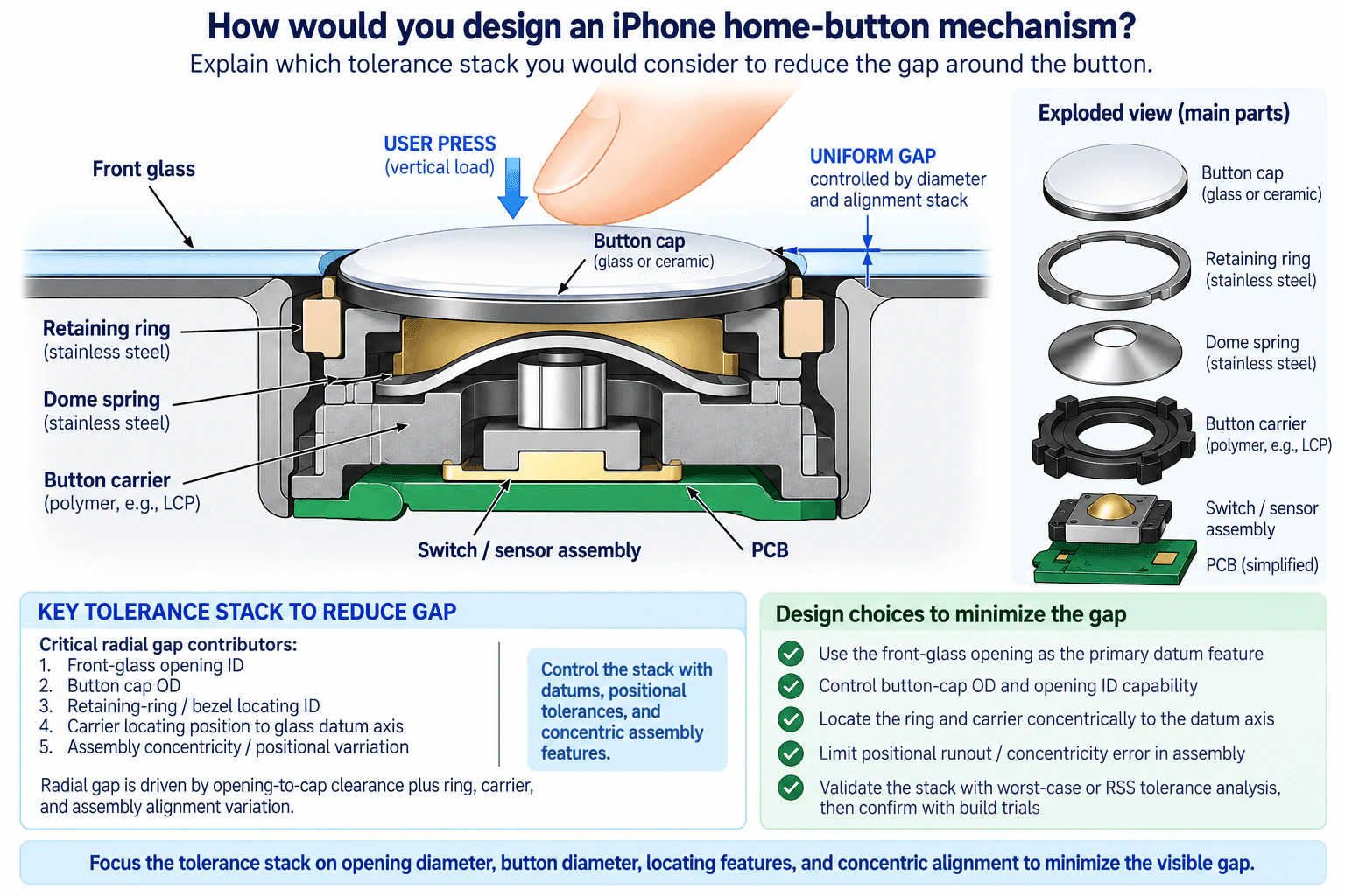
I would treat it as a guided axial button assembly with a button cap, retaining ring, dome spring, button carrier, switch or sensor assembly, PCB, and the front-glass opening as the key visible interface. To minimize the gap, I would control both size and alignment: the front-glass opening ID, button-cap OD, retaining-ring or bezel locating ID, carrier position relative to the glass-opening axis, and final assembly positional variation. For perfectly centered parts, the nominal radial clearance is (D_open - D_button) / 2, but any radial offset reduces the gap on one side, so diameter tolerances and concentric alignment must be controlled together. I would verify the stack with worst-case analysis, use RSS only when the statistical assumptions are justified, and confirm the result with dimensional inspection and build trials.
Detailed Explanation
I would begin by separating the problem into two functions. First, the button must move in the vertical direction when the user presses it and return reliably. Second, the button must remain visually centered inside the front-glass opening with a small, uniform radial gap.
The concept uses a button cap, retaining ring, stainless-steel dome spring, polymer button carrier, switch or sensor assembly, PCB, and front glass. The carrier guides the button motion, the dome spring provides the return and tactile spring behavior shown in the concept, and the switch or sensor assembly detects actuation. This is a hypothetical engineering architecture, not a claim about a proprietary Apple implementation.
For the visible gap, I would make the front-glass opening the primary locating reference for radial alignment. Let D_open be the front-glass opening inside diameter and D_button be the button-cap outside diameter. If the two parts are perfectly centered, the nominal radial clearance is:
c_nom = (D_open - D_button) / 2
where c_nom is the nominal radial gap.
That diameter calculation is only the first part of the tolerance stack. The button can also shift laterally because of variation in the retaining-ring or bezel locating diameter, the carrier locating position, and final assembly location. If e is the total radial offset between the button center and the glass-opening center, a useful geometric relationship is:
c_min = c_nom - e c_max = c_nom + e
This shows why reducing the diameter difference alone is not enough. A small nominal clearance can still produce rubbing on one side if the locating stack allows too much eccentricity. The critical radial contributors are therefore:
Front-glass opening ID.
Button-cap OD.
Retaining-ring or bezel locating ID.
Carrier locating position relative to the glass-opening datum axis.
Assembly positional variation.
I would control the ring and carrier from the same radial reference as the visible glass opening so that loosely controlled internal features do not determine the button's cosmetic position. The glass-opening axis provides the radial locating reference, while an appropriate glass surface or structural interface can provide the axial reference needed to control button height and assembly seating. For the radial-gap problem, the important requirement is that the cap, ring, and carrier remain concentrically aligned with the opening.
The tolerance strategy has two parts. First, control size by setting manufacturable tolerances and process capability requirements for the glass-opening ID, button-cap OD, and retaining-ring or bezel locating diameter. Second, control location by defining datums and positional controls for the ring, carrier, and assembly interfaces so that their accumulated lateral offset remains small.
I would not simply specify the tightest possible tolerances everywhere. Tight tolerances increase manufacturing cost, inspection effort, and potentially scrap. Instead, I would identify the dominant contributors to the minimum gap and spend tolerance where it provides the greatest improvement. If the carrier location dominates the variation, tightening the button OD may provide little benefit. A sensitivity or tolerance-contribution review helps prioritize the dimensions that matter most.
The design also needs enough functional clearance. A smaller visible gap improves appearance, but if the minimum gap approaches zero, manufacturing variation, contamination, wear, thermal effects, or assembly shift can cause the button cap to rub or bind against the surrounding opening. The target should therefore balance cosmetic appearance against reliable free motion and production capability.
For the material concept shown, a glass or ceramic cap provides a hard visible surface, a stainless-steel retaining ring provides a durable locating feature, a stainless-steel dome spring supplies elastic return behavior, and a molded polymer carrier such as LCP can provide lightweight guided motion and manufacturable locating geometry. The exact material grades, dimensions, loads, and life requirements are unknown and should not be invented; they would be selected from the product requirements and supplier capability data.
For tolerance analysis, I would first run a worst-case stack for any hard functional requirement such as avoiding contact or binding. That establishes whether the assembly can remain functional at the allowed dimensional extremes. If the production processes are stable and their distributions are understood, I would also use an RSS-style statistical analysis to estimate typical manufacturing variation. RSS should not replace a worst-case check when interference is unacceptable unless the organization has explicitly accepted a statistical risk criterion.
I would also consider failure modes. An excessive lateral offset can create an uneven cosmetic gap or rubbing. Too much clearance can make the button look loose or allow unwanted lateral movement. Carrier wear can increase play over life. The dome spring can lose force through fatigue or permanent set. Assembly errors can shift the carrier or retaining ring. Misalignment between the moving assembly and switch or sensor can affect actuation. These failure modes should drive the tolerance allocation and validation plan.
Validation would include dimensional inspection of the front-glass opening, button OD, locating features, and assembled button position. I would measure the radial gap at several angular locations around the button so that both overall clearance and eccentricity are captured. I would also perform assembly trials across normal process variation, actuation testing, repeated-cycle testing, wear inspection, and environmental testing appropriate to the product. The measured production variation would then be compared with the tolerance model, and the design or assembly process would be adjusted if the real stack is larger than predicted.
Useful Questions to Ask the Interviewer
Is the main priority cosmetic gap, smooth motion, tactile feel, durability, sealing, or a combination of these?
What minimum and maximum radial gap are acceptable around the full circumference?
What manufacturing processes and process-capability data are available for the front-glass opening, button cap, retaining ring, and carrier?
Should the mechanism use a tactile switch, a sensor-based input, or is the actuation technology intentionally unspecified?
What life-cycle, contamination, temperature, wear, and drop conditions must the mechanism survive?
Is the assembly intended to be serviceable, or can the button mechanism be permanently integrated into the enclosure or display assembly?
How to Explain It in an Interview
I would explain that the visible gap is controlled by both diameter and alignment. I would use the front-glass opening as the radial locating reference, calculate the nominal clearance from the opening ID and button OD, and then add the positional variation introduced by the retaining ring, carrier, and final assembly. The design goal is to keep the minimum gap large enough to prevent rubbing while keeping the maximum gap small and visually uniform. I would locate the retaining ring and carrier from the same datum structure as the glass opening, control the dominant dimensional contributors according to manufacturing capability, check the design with worst-case tolerance analysis, use RSS where statistically justified, and then verify the model with dimensional measurements and build trials. The central tradeoff is that reducing the nominal gap improves appearance but makes the mechanism more sensitive to manufacturing variation, misalignment, contamination, wear, and assembly error.
Practical Complexity & Trade-offs
The main difficulty is controlling several small variations at the same time. Tightening the glass-opening ID or button OD can reduce the visible gap, but tighter manufacturing tolerances usually cost more and may increase scrap. Better locating features on the retaining ring and carrier can reduce off-center assembly, but those features also need reliable manufacturing and inspection. A larger nominal gap gives more protection against rubbing and variation but looks less refined. Worst-case analysis is useful for hard no-contact limits, while RSS can estimate normal production variation when its statistical assumptions are valid. The final decision should be based on tolerance capability, assembly repeatability, cost, wear, and physical validation.
Why Interviewers Ask This
This question tests whether the candidate can turn a small consumer-product interface into a complete mechanical design problem: define requirements and interfaces, establish the load and motion path, choose locating features and materials, construct a tolerance stack, control the visible gap, account for manufacturing and assembly variation, identify failure modes, and define a practical validation plan without inventing proprietary product details.
Interviewer may ask next
How would you validate that the tolerance stack produces a uniform gap in production?
I would inspect the glass-opening ID, button-cap OD, retaining-ring or bezel locating feature, carrier location, and assembled button center relative to the glass-opening axis. On the completed assembly, I would measure the radial gap at several angular locations rather than at only one point. From those measurements I could separate average clearance from eccentricity. I would compare the measured distributions with the worst-case and statistical tolerance models and run build trials across representative process variation. If the measured gap spread is larger than predicted, I would trace the dominant contributor through the locating chain and change that tolerance, locating feature, fixture, or assembly process.
What would you change if the required visible gap became much smaller?
I would first recalculate the minimum clearance after including diameter tolerances and the full lateral locating stack. If the reduced target causes the minimum gap to approach zero, I would not simply shrink the nominal clearance. I would reduce the dominant variation sources by improving capability on the opening ID and button OD, locating the retaining ring and carrier more directly from the glass-opening axis, reducing lateral carrier play, and improving assembly fixturing. I would then repeat worst-case and statistical analysis and verify the design with build trials. If the required cosmetic gap still conflicts with reliable free motion or realistic manufacturing capability, I would explicitly present that tradeoff instead of accepting a high rubbing risk.
42. How would you design an automated sticker peeler?Mechanical DesignHard
i Question Details
The machine must remove the backing from a sticker.
Short Interview Answer (30-60 seconds)
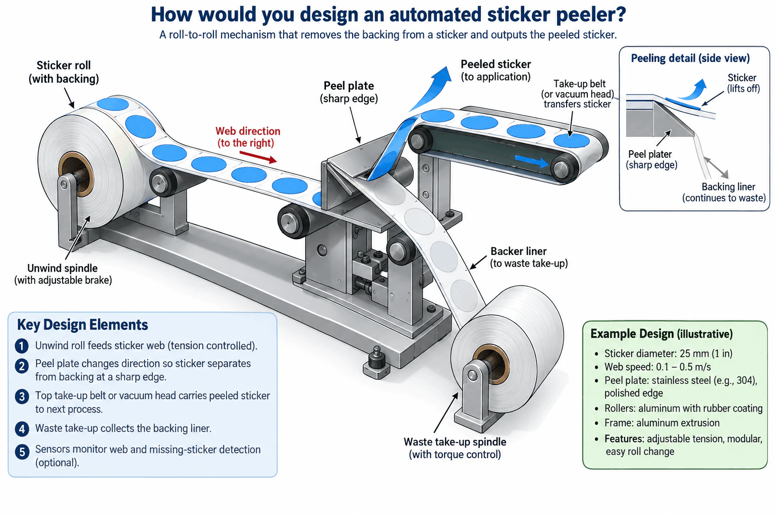
I would use a controlled roll-to-roll mechanism. The sticker web would unwind from a braked spindle, pass through guide rollers, and bend sharply around a peel plate. The backing liner would follow the sharp turn toward a torque-controlled waste take-up spindle, while the sticker would tend to continue forward and separate because it does not conform as readily to the small bend radius. A take-up belt or vacuum head would then carry the peeled sticker to the next process. I would make web tension and peel geometry adjustable, add sensing where needed, and validate separation reliability, adhesive damage, alignment, jams, and roll-change serviceability across the required sticker and liner range.
Detailed Explanation
The basic design is a roll-to-roll web-handling system built around one key mechanical action: force the backing liner to make a sharp change in direction while allowing the sticker to continue toward the output. The system boundary starts at the sticker roll and ends with two outputs: a peeled sticker going to an applicator or downstream process, and the spent backing liner going to a waste take-up spindle.
I would first define measurable requirements rather than assume one sticker geometry. Important inputs include sticker width and length, liner thickness and stiffness, adhesive behavior, required throughput, acceptable peel damage, roll diameter and mass, placement accuracy, allowable machine envelope, cleaning needs, and how often operators change rolls. The illustrative design shows a 25 mm sticker and a web speed of 0.1–0.5 m/s, but I would treat those values as hypothetical examples rather than fixed requirements until the interviewer confirms them.
The primary load path is through the web. The unwind spindle provides controlled resistance, guide rollers establish the web path, the peel plate redirects the backing liner, and the waste take-up spindle supplies the downstream pulling action. The design goal is enough web tension to maintain stable tracking and peeling without stretching the liner, distorting the sticker, damaging the adhesive, or causing slip at the rollers.
At the peel plate, the combined sticker-and-liner web approaches a sharp edge. The backing liner bends around the edge and travels downward toward the waste take-up spindle. The sticker does not conform as readily to that small bend radius, so it tends to continue forward and separates from the liner. A take-up belt or vacuum head then supports and transfers the peeled sticker so it does not fall, curl excessively, or reattach to the liner.
For tension control, I would use an adjustable brake on the unwind spindle and controlled torque on the waste take-up spindle, matching the arrangement shown in the design. The important engineering issue is that the waste roll radius grows as liner accumulates. For spindle torque T and current roll radius r, the approximate liner tension is F = T/r. Therefore, constant spindle torque would not maintain constant web tension as the waste roll grows. If the application needs tighter control, I would compensate torque as radius changes or use closed-loop tension control with a dancer or tension sensor.
The peel plate should have a small, consistent edge radius suitable for the actual liner, sticker, and adhesive system, but I would not select that radius without testing production materials. The illustrative design uses a polished stainless-steel peel plate, aluminum rollers with a rubber coating, and an aluminum-extrusion frame. Those are reasonable prototype choices because the peel plate can provide a durable, cleanable surface, coated rollers can provide useful traction, and extrusion makes adjustment and service access easier. They remain design choices to validate rather than universal requirements.
The interfaces should be adjustable. The unwind and waste spindles need repeatable roll location and convenient loading. Guide rollers need sufficient width, stiffness, and alignment to prevent lateral web walking. The peel plate position should permit adjustment of the incoming web path and separation geometry. Bearings, shafts, fasteners, spindle hubs, and structural members should be sized from the actual roll mass, web tension, belt forces, acceleration, and duty cycle once those values are known. Fits and tolerances should be based on the required runout, alignment, repeatability, manufacturability, and service needs rather than invented in advance.
Optional sensors can detect web presence, sticker position, or a missing sticker before the peel edge. That information can synchronize the mechanism with a downstream applicator and stop the machine after a jam, depleted roll, or missed label. Sensor selection depends on the optical and physical properties of the actual sticker and liner, so I would validate detection using production materials.
Important failure modes include insufficient separation causing the sticker to remain on the liner, excessive tension tearing or stretching the liner, excessive peel aggressiveness damaging the sticker or adhesive, web tracking errors causing edge contact, liner slip causing position error, the growing waste roll changing tension, sticker curl after release, adhesive contamination at the peel edge, and failure of the take-up belt or vacuum head to capture the peeled sticker. The design should provide easy access to the peel plate, guide rollers, and both spindles for cleaning, clearing jams, and changing rolls.
For design for manufacturing and assembly, I would minimize unique brackets, use accessible fasteners, provide repeatable datums for aligning the peel plate and rollers, and make the unwind and waste modules serviceable without disturbing the entire web path. In real equipment, accessible rotating parts and pinch points would also require an appropriate safeguarding strategy based on the actual machine and applicable requirements.
Useful Questions to Ask the Interviewer
What sticker sizes, liner materials, roll diameters, and adhesive types must the machine handle? These determine the web path, peel geometry, roller width, and adjustment range.
What throughput or cycle time is required? This affects drive sizing, acceleration, tension-control needs, and whether continuous or intermittent motion is better.
What happens to the peeled sticker next? A sticker collected after peeling has different handling requirements from one transferred directly to an applicator.
How much position error and sticker damage are acceptable? These define the required tracking, sensing, stiffness, and control accuracy.
How often will rolls be changed, and how much operator access is required? This affects spindle design, threading, guarding, and serviceability.
What production materials and environmental conditions will be used? Peel behavior depends on the real sticker, backing liner, adhesive, temperature, and contamination conditions.
How to Explain It in an Interview
I would explain the machine from left to right along the material path. First, the adjustable-brake unwind spindle feeds the sticker-and-backing web. Guide rollers establish alignment and a controlled path. At the peel plate, the liner is forced around a sharp turn while the sticker continues forward and separates. A take-up belt or vacuum head captures the peeled sticker and transfers it to the next operation. The backing liner travels downward and is wound onto the torque-controlled waste take-up spindle.
Then I would explain the main engineering decision: reliable peeling depends on the interaction of web tension, liner bending behavior, sticker stiffness, adhesive behavior, peel-edge geometry, and speed. I would not assume that one peel radius or one tension setting works for every material. I would build an adjustable prototype and test the intended material range.
For validation, I would run representative sticker and liner combinations at the minimum, nominal, and maximum required speeds and throughout the full supply-roll and waste-roll diameter ranges. I would record separation success, sticker position error, liner tears, jams, missed stickers, visible sticker or adhesive damage, web tracking, and tension stability. I would also test roll changes, threading, cleaning, jam recovery, and repeated operation. Any recurring failure would feed back into peel-edge geometry, web tension, guide alignment, transfer support, sensing, or control settings before design review and production release.
Practical Complexity & Trade-offs
The simplest machine uses a braked unwind spindle, guide rollers, one peel plate, and a driven waste take-up spindle. It is inexpensive and easy to build, but its tension can change as roll diameters change. Adding closed-loop tension control, sensing, and a synchronized take-up belt or vacuum transfer increases cost and control complexity but improves repeatability, especially at higher speed. A tighter peel geometry can improve separation for some materials but can also increase liner stress or sensitivity to material variation. More adjustment supports more sticker formats but adds setup time and additional opportunities for misalignment. The best design balances reliable peeling, sticker protection, throughput, manufacturability, maintainability, and changeover time.
Why Interviewers Ask This
This question tests whether I can turn a simple functional requirement into a practical mechanical system. The interviewer is evaluating how I define requirements, control the web path and tension, create reliable separation at the peel edge, select mechanical interfaces and materials, anticipate failure modes, and plan validation rather than choosing components before understanding the load cases.
Interviewer may ask next
How would you validate that the peel mechanism works reliably before releasing the design?
I would test the actual sticker and liner combinations across the required speed range and from full to nearly empty supply rolls while the waste roll grows from empty to full. I would measure separation success, sticker position, web tracking, liner tears, jams, sticker curl, adhesive damage, and tension stability. I would deliberately vary peel-plate position and tension to identify operating margins rather than validate only one nominal setting. I would also test roll loading, threading, cleaning, jam recovery, and repeated cycles. The resulting failure modes would determine whether I need changes to peel geometry, tension control, guides, sensing, or the sticker-transfer mechanism.
What would you change if the machine had to run much faster?
At higher speed I would focus on dynamic tension control, web inertia, roller balance, sticker capture, and synchronization. A simple brake and constant take-up torque may no longer maintain stable tension, so I would consider a dancer or tension sensor with closed-loop drive control. I would minimize unsupported web spans, check roller and shaft stiffness, and control acceleration to reduce transient tension spikes. The take-up belt or vacuum head would need to match sticker velocity closely so the sticker does not curl, slip, or reattach. I would then repeat validation at the new speed range because a peel geometry that works slowly may not remain reliable under higher dynamic loads.
43. Which CAD software are you most comfortable using, and why?Cad And Gd&tEasy
Short Interview Answer (30-60 seconds)
I am most comfortable using SolidWorks because it supports the mechanical-design workflow well, from parametric part modeling and assemblies through production drawings and GD&T. I focus on building models around stable design intent, using meaningful dimensions and references so expected design changes do not break downstream features. I also use CAD to check assembly interfaces, clearances, and manufacturability, then communicate the design with appropriate dimensions, datums, tolerances, and revision control. If a company uses another major CAD platform, I would need to learn its specific interface and workflow, but the underlying engineering principles are transferable.
Detailed Explanation
I would choose SolidWorks as the CAD software I am most comfortable using because it supports the complete mechanical-design workflow: parametric part modeling, assemblies, drawings, tolerancing, and controlled design changes.
The important point is that being comfortable with CAD is more than knowing commands. I try to build models that preserve design intent. That means using meaningful dimensions and constraints, choosing stable references, keeping feature relationships understandable, and structuring the model so expected changes can be made without causing unnecessary downstream failures.
For assemblies, I use mates or constraints to represent the intended physical relationships between parts. I check important interfaces such as clearance, alignment, interference, and motion where applicable. I also consider whether the assembly structure supports practical manufacturing, inspection, service, and revision workflows.
When I create a manufacturing drawing, I separate nominal geometry from allowable variation. Size tolerances control feature size, while GD&T can control characteristics such as form, orientation, and location. I would choose datum features from functional interfaces rather than simply selecting convenient surfaces. For example, if a mounting face establishes how a component sits in the assembly, that surface could be a logical primary datum feature. A locating feature could then help establish the remaining degrees of freedom.
I also avoid making tolerances tighter than function requires. A tighter tolerance can increase machining and inspection cost and may exceed the capability of the intended process without providing additional functional value. For assemblies, I consider tolerance-stack effects so that individual part variation still produces the required clearance, fit, or alignment at the assembly level.
Revision control is equally important. A released model or drawing needs to identify the current design definition clearly so engineering, manufacturing, quality, and suppliers are working from the correct revision. If the organization uses model-based definition, the same principle applies: product-manufacturing information associated with the 3D model must be controlled and communicated consistently.
Useful Questions to Ask the Interviewer
Which CAD platform and version does the mechanical team use most often?
Does the company primarily release traditional 2D drawings, model-based definition, or a combination of both?
How are CAD models and drawings controlled through the company's PDM or PLM system?
How much responsibility does the mechanical engineer have for GD&T, tolerance-stack analysis, drawing release, and design reviews?
These questions help clarify the actual CAD workflow because organizations divide modeling, detailing, tolerance definition, release, and configuration-control responsibilities differently.
How to Explain It in an Interview
I would connect my software familiarity to engineering decisions rather than listing commands. For example: I am most comfortable with SolidWorks because I can use it across the mechanical-design workflow, from parametric modeling through assemblies and production drawings. I build models around stable design intent so expected changes do not cause unnecessary feature failures. In drawings, I use dimensions and GD&T to communicate functional requirements while avoiding unnecessarily restrictive tolerances. I also consider manufacturability, inspection, assembly stack-up, and revision control. If the team uses another CAD package, I would learn its interface and company-specific workflow, while applying the same underlying mechanical-design principles.
Practical Complexity & Trade-offs
The main tradeoff is between modeling quickly and building a model that remains reliable when the design changes. A fast model with fragile references can create rework later. There is also a tolerancing tradeoff: tighter tolerances can provide greater dimensional control, but they may increase manufacturing and inspection cost. Good CAD work balances design intent, model stability, manufacturability, inspection capability, assembly requirements, tolerance stack-up, and revision control. The software interface can change, but those engineering principles remain important.
Why Interviewers Ask This
Interviewers ask this to understand whether you can use CAD as an engineering tool rather than only as a geometry-creation tool. They are evaluating how effectively you can build stable parametric models, manage assemblies, communicate design intent through drawings and GD&T, control revisions, and adapt to the CAD and data-management workflow used by their organization.
Interviewer may ask next
How would you verify that a CAD model and drawing are ready for release?
I would review the model for stable design intent, appropriate sketch constraints, unintended or fragile references, feature errors, and assembly interference where relevant. I would then check that the drawing communicates the functional requirements without unnecessary duplication or over-constraint. I would verify that datum features and GD&T reflect the part's functional interfaces, review important tolerance stacks, confirm required manufacturing information, and make sure the correct model and drawing revision is being released through the organization's document-control process. I would also involve manufacturing and quality when their input is needed because geometry can be correct while still being unnecessarily difficult to manufacture or inspect.
What would you do if the company used a CAD package you had not worked with before?
I would first learn the company's standard modeling and release workflow instead of trying to reproduce another CAD system's habits exactly. I would identify the equivalent tools for sketches, parametric features, reference geometry, assemblies, drawings, GD&T, configurations, and revision management. The commands and interface may differ, but concepts such as design intent, functional datum selection, tolerance control, assembly relationships, manufacturability, and revision control are transferable. I would use the company's templates and standards, practice on representative parts, and seek review of early work so I could adapt without introducing inconsistent modeling practices.
44. How would you ensure two machined plates with matching hole patterns align for bolting?Cad And Gd&tMedium
Short Interview Answer (30-60 seconds)
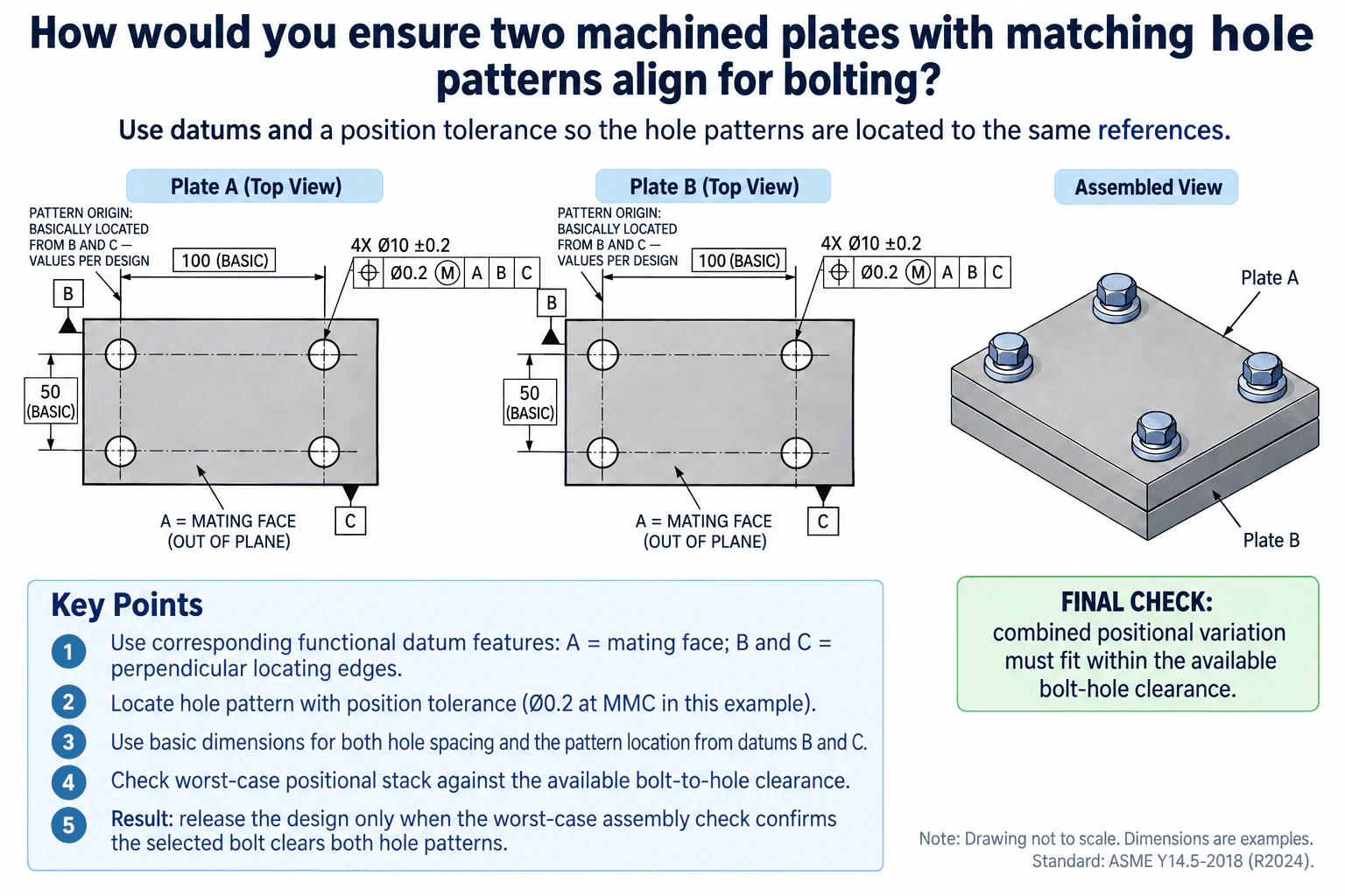
I would reference both plates from corresponding functional datums, with the mating face as datum A and perpendicular locating edges as datums B and C. I would locate the hole patterns with basic dimensions and control their axes with a position tolerance, using MMC where appropriate for the clearance holes. Hole size and geometric position would remain separate requirements. Finally, I would check the combined worst-case positional variation of both plates against the available bolt-to-hole clearance before releasing the design.
Detailed Explanation
The key is to control both plates from functional assembly references rather than relying only on nominal CAD coordinates. In the illustrated approach, datum A is the mating planar face, while datums B and C are perpendicular locating edges. Those physical datum features establish the datum reference framework used to orient and locate the hole patterns.
The theoretically exact hole pattern is defined with basic dimensions. That means the drawing needs basic dimensions for both the spacing between holes and the location of the pattern from datums B and C. The hole axes are then controlled by a position feature control frame relative to A, B, and C. Hole diameter remains a separate size requirement.
In the illustrated example, each plate has 4X Ø10 ±0.2 holes and a Ø0.2 position tolerance at MMC relative to A|B|C. These are hypothetical example values, not universal design requirements. At MMC, an internal feature such as a hole is at its smallest permitted diameter. If the actual hole is larger than its MMC size, the position control can gain bonus tolerance equal to the hole's departure from MMC, while the functional boundary remains protected.
The important assembly check comes after defining the GD&T. Both plates can deviate within their permitted position zones, so two nominally identical patterns can still shift relative to each other. I would therefore evaluate the combined positional variation of the two plates against the bolt-to-hole clearance available at the limiting conditions. If the tolerance stack does not leave enough clearance for the selected bolt, the drawing is not ready for release even though each plate may individually satisfy its own dimensions.
For this drawing basis, ASME Y14.5-2018 (R2024) is the applicable GD&T standard. I would keep the datum references, basic dimensions, position control, and material-condition modifiers consistent with that standard and with the real assembly function.
Useful Questions to Ask the Interviewer
Are the bolts intended only to clamp the plates, or must they also locate the plates precisely?
Which physical surfaces actually locate the two plates during assembly?
What bolt diameter and clearance-hole range are required?
What machining process will produce the holes, and what positional capability can it hold economically?
How will production parts be inspected relative to the functional datums?
How to Explain It in an Interview
I would start by identifying the functional interfaces. The mating face becomes datum A because it establishes how the plates seat together. I would then choose two perpendicular locating edges as datums B and C so the drawing has a stable in-plane reference system. I would use corresponding functional datum features on both plates so their hole patterns are defined from equivalent assembly references.
Next, I would use basic dimensions to define the theoretically exact hole spacing and the theoretically exact location of the pattern from B and C. I would avoid relying only on chained plus-minus dimensions because they can create an uncontrolled or difficult-to-understand location stack.
Then I would apply a position tolerance to the hole pattern relative to A, B, and C. The hole-size tolerance controls how large or small each hole may be, while the position tolerance controls where each hole axis may lie relative to the datum reference framework. Those are different requirements and both affect assembly.
For clearance holes, MMC can be useful because the smallest allowed hole gives the least assembly clearance. If a produced hole is larger than its MMC size, the extra size can provide bonus position tolerance equal to the departure from MMC. I would use that modifier only where it is functionally appropriate for the feature of size.
Finally, I would perform the assembly tolerance check. I would consider the allowed positional variation of both plates together and compare it with the clearance available between the selected bolt and both holes. If the worst-case condition does not provide adequate clearance, I would change the design rather than assume assembly will work. Depending on the requirement, options could include increasing clearance-hole size, tightening position tolerance if the manufacturing process can support it, changing the datum strategy, or adding dedicated locating features such as dowels when precise plate-to-plate location is required.
Before release, I would verify that the datum scheme represents the real assembly, that the basic dimensions completely locate the pattern, that the position control is inspectable, that the manufacturing process can achieve the specified tolerances, and that the worst-case assembly analysis confirms bolt passage through both plates.
Practical Complexity & Trade-offs
The main tradeoff is assembly reliability versus manufacturing precision and cost. More bolt-to-hole clearance makes assembly easier, but it can allow more relative movement between plates. A tighter position tolerance improves hole-pattern alignment but may require more accurate machining and inspection. MMC can provide bonus tolerance when a hole is produced larger than its smallest allowed size, which can make manufacturing easier without violating the functional boundary. Functional datum selection also matters: if the datums do not represent the real mating and locating surfaces, a part can inspect correctly yet still assemble poorly. The final decision should therefore be based on the combined tolerance stack of both plates, not just nominal CAD alignment.
Why Interviewers Ask This
The interviewer is testing whether you can convert assembly function into clear drawing intent. They want to see whether you can choose functional datums, distinguish size tolerance from geometric position tolerance, use basic dimensions correctly, apply MMC appropriately, understand tolerance accumulation between mating parts, and verify assembly instead of assuming that nominally matching CAD hole patterns will always align.
Interviewer may ask next
How would you validate that the tolerance scheme will actually allow the bolts to pass through both plates?
I would define the actual bolt size and the permitted hole-size range, determine the available bolt-to-hole clearance at the limiting material conditions, and then include the allowed positional variation of both plates in the worst-case assembly stack. I would also confirm that the datum features match how the plates are physically located during assembly. If the combined positional variation remains within the available assembly clearance, the scheme supports bolt passage. I would then verify production parts by inspecting the datum features, hole sizes, and hole positions and, where appropriate, by using a representative functional gage or assembly check.
What would you change if the two plates must locate very accurately relative to each other rather than simply allow bolts to pass through?
I would normally separate the locating function from the fastening function. I would introduce dedicated locating features, such as properly toleranced dowel holes and pins, and make those functional locating features part of the datum strategy. The bolts could then provide clamping while the locating features control repeatable plate-to-plate position. I would revise the tolerance analysis to include the locator fit, locator position, hole-pattern position, and manufacturing capability without over-constraining the assembly.
45. How can you reduce the linear tolerance stack of two mating parts?Cad And Gd&tMedium
i Question Details
Both mating parts use ordinary plus/minus dimensional tolerances.
Short Interview Answer (30-60 seconds)
For two mating parts with ordinary plus/minus dimensions, I would first calculate the worst-case stack and identify the dimensions that actually control the fit. Their tolerance magnitudes add in a worst-case stack. I would then tighten only the critical dimensions as much as the process can reliably hold, remove unnecessary chained dimensions, reference critical features from stable functional datums where appropriate, and use GD&T to control geometric variation that affects assembly. The goal is to reduce assembly variation without over-tolerancing the parts.
Detailed Explanation
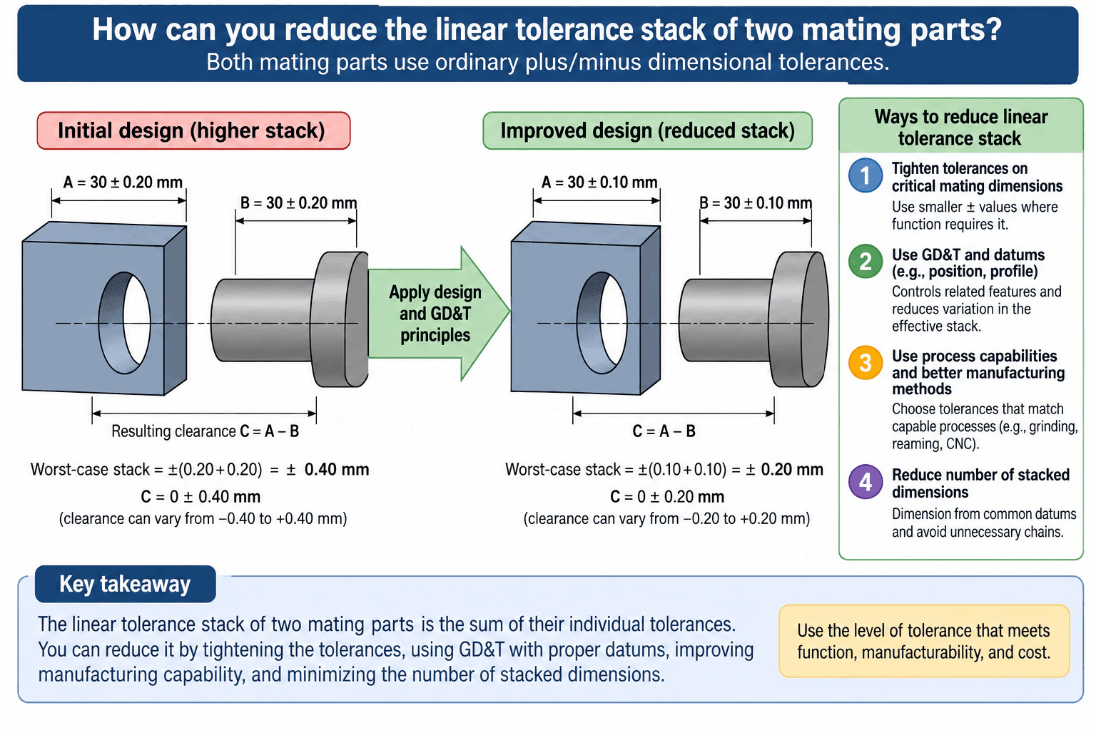
With ordinary plus/minus dimensions, reducing a linear tolerance stack means reducing the independent dimensional variations that contribute to the final mating condition. If the assembly relationship is C = A - B, the nominal dimensions subtract, but in a worst-case analysis the absolute tolerance contributions add.
Using the hypothetical example shown in the approved diagram, A = 30 ± 0.20 mm and B = 30 ± 0.20 mm. The nominal result is C = 30 - 30 = 0 mm. The worst-case tolerance is ±(0.20 + 0.20) = ±0.40 mm, so C can range from -0.40 mm to +0.40 mm. If both critical dimensions can instead be manufactured as 30 ± 0.10 mm, then the worst-case result becomes C = 0 ± 0.20 mm, with a range from -0.20 mm to +0.20 mm. The reduction comes directly from reducing the contributing dimensional tolerances.
A good drawing strategy is to identify the functional mating dimensions first. Those dimensions deserve the tightest control because they directly determine clearance or interference. Other dimensions should remain as loose as function allows rather than being tightened unnecessarily.
Another way to reduce accumulation is to minimize unnecessary dimension chains. If a critical mating feature is located through several chained dimensions, every independent tolerance in that chain can contribute to the final assembly variation. Referencing the critical feature more directly from a stable functional datum feature can remove unnecessary intermediate contributions and make design intent easier to manufacture and inspect.
GD&T can complement the size-tolerance strategy when geometric variation also affects the assembly. A plus/minus size or linear tolerance controls dimensional variation, while geometric controls such as position, profile, flatness, parallelism, or perpendicularity control the applicable form, orientation, or location relationship. Datum features establish repeatable references for those geometric controls. GD&T does not automatically make an independent plus/minus size stack smaller; it is useful when a more functional geometric control reduces or better limits the variation that matters at the mating interface.
The final tolerance values must also match manufacturing and inspection capability. Processes such as machining, reaming, or grinding may support different practical tolerance levels. Specifying a tolerance tighter than the process can consistently hold can increase machining effort, inspection, scrap, rework, and cost without producing a dependable functional benefit.
Useful Questions to Ask the Interviewer
What assembly condition matters most: minimum clearance, maximum clearance, interference, alignment, or another functional requirement?
Which dimensions directly determine that condition?
Are the two dimensions independent, or are additional dimensions included in the actual tolerance chain?
What manufacturing processes will produce the mating features, and what tolerances can those processes hold consistently?
Which physical surfaces or features functionally locate the parts and should therefore be considered as datum features?
Does geometric variation such as position, perpendicularity, or flatness also affect the mating condition?
How to Explain It in an Interview
I would begin with the assembly equation and calculate the current worst-case condition. If C = A - B and the two dimensions are independently toleranced, I add the absolute tolerance contributions for worst-case analysis. In the worked example, ±0.20 mm on each dimension produces ±0.40 mm of possible assembly variation. Reducing both critical tolerances to ±0.10 mm reduces that variation to ±0.20 mm.
Next, I would identify whether every dimension in the stack is necessary. If a critical mating feature is located through several chained dimensions, I would consider dimensioning it more directly from a stable functional datum feature so unnecessary intermediate tolerances do not accumulate.
Then I would separate dimensional size control from geometric control. I would keep plus/minus tolerances where they define the required size or linear distance and use suitable GD&T where form, orientation, or location variation affects the assembly. Datum features would be selected from functional interfaces so manufacturing and inspection reproduce how the part is located in service.
Finally, I would validate the proposed tolerance scheme against both function and process capability. I would recalculate the worst-case limits, verify that the required clearance or interference remains acceptable, check whether geometric variation adds another contributor, and confirm that the specified tolerances can be manufactured and inspected consistently. The best design is not the one with the tightest tolerances everywhere; it is the least restrictive tolerance scheme that reliably protects assembly function.
Why Interviewers Ask This
Interviewers want to see whether you can translate assembly function into practical drawing requirements instead of simply tightening every tolerance. The key judgment is understanding how independent plus/minus tolerances accumulate, identifying which dimensions actually drive fit, distinguishing size tolerances from geometric controls, and balancing tighter control against manufacturing capability, inspection effort, cost, and functional requirements.
Interviewer may ask next
How would you verify that the reduced tolerance stack is sufficient before releasing the drawing?
I would write the complete assembly stack equation, identify every independent contributing dimension, and calculate the worst-case minimum and maximum assembly condition. I would compare those limits with the required functional clearance or interference. I would also check whether geometric errors such as position, perpendicularity, or flatness contribute to the mating condition. Finally, I would confirm that the proposed tolerances and geometric controls can be manufactured and measured consistently before drawing release.
What would you do if tightening both mating dimensions from ±0.20 mm to ±0.10 mm were too expensive?
I would avoid tightening both dimensions automatically. I would determine which tolerance contributions have the greatest effect on function and which features can be controlled most economically. I would also look for unnecessary chained dimensions that can be removed, consider more direct dimensioning from functional datum features, and use appropriate GD&T if geometric variation rather than size variation is driving the assembly problem. The objective is to meet the required fit with the lowest practical manufacturing and inspection burden.
46. How do you turn an engineer’s or architect’s sketches into detailed technical drawings?Cad And Gd&tEasy
Short Interview Answer (30-60 seconds)
I first review the sketch and clarify anything that is missing or ambiguous, such as dimensions, interfaces, materials, tolerances, and the intended manufacturing or construction method. Then I create accurate CAD geometry using stable references and design intent, select the views and sections needed to define the design clearly, and add dimensions, notes, tolerances, and GD&T where function requires them. I check the drawing against the original intent, mating interfaces, manufacturing capability, and inspection needs. Finally, I verify the title block, drawing standard, revision information, and required checks before release.
Detailed Explanation
Turning a sketch into a detailed technical drawing is not simply tracing lines. The goal is to translate design intent into an unambiguous engineering definition that another person can manufacture, construct, assemble, or inspect correctly.
Useful Questions to Ask the Interviewer
Is the sketch conceptual, or are the shown dimensions intended to be final requirements?
What are the critical functional interfaces with mating parts, assemblies, or surrounding structures?
Which dimensions are fixed requirements, and which can be established during detailing?
What material, manufacturing process, or construction method is expected?
Are there required fits, clearances, surface requirements, geometric controls, or inspection requirements?
Which drawing standard, units, and company drafting practices should be followed?
Is the released drawing the controlling definition, or is a model-based definition workflow being used?
If those details are not supplied, I would identify them as unknowns and obtain clarification rather than inventing requirements.
How to Explain It in an Interview
I would use a structured drawing strategy.
First, I interpret the sketch and identify the design intent. I separate supplied information from assumptions and unresolved details. I look for the main geometry, functional surfaces, mating interfaces, symmetry, hole patterns, reference locations, and any dimensions or notes already specified by the engineer or architect.
Second, I create the CAD geometry. For a 3D mechanical part, I build features from stable reference planes, axes, centerlines, datums, and meaningful geometric relationships so later design changes do not unnecessarily break the model. I fully define the geometry where appropriate without introducing conflicting or redundant constraints.
Third, I select the minimum set of drawing views needed to communicate the design clearly. Depending on the geometry, these can include orthographic views, section views, detail views, auxiliary views, and an isometric reference view. I avoid unnecessary views that duplicate information without improving clarity.
Fourth, I add dimensions according to function and design intent. Dimensions should define the required geometry without unnecessary duplication. Where possible, I dimension important features from functional references instead of creating long chains of dimensions that can accumulate tolerance variation.
Fifth, I establish appropriate tolerance controls. Size tolerances control dimensions such as diameter, width, thickness, or length. When geometric relationships are functionally important, I use GD&T according to the applicable drawing standard and edition. I choose datum features from the physical features that functionally locate or orient the part. Those physical datum features are used during inspection to establish the associated theoretically exact datums and datum reference framework. Controls such as position, flatness, perpendicularity, parallelism, profile, or runout are applied only when they communicate a real functional requirement. Material-condition modifiers, such as maximum material condition, are used only on eligible features and geometric controls where the applicable standard permits them.
Sixth, I consider tolerance-stack effects at important interfaces. For mating components, I check whether the combined dimensional and geometric variation can still provide the required clearance, interference, alignment, or assembly condition. If a proposed tolerance is tighter than the expected process can reliably achieve, I would discuss changing the tolerance, manufacturing process, inspection method, or design rather than placing an unrealistic requirement on the drawing.
Seventh, I add the required supporting information. Depending on the application, this can include material, finish, surface requirements, hole and thread callouts, units, scale, general tolerances, drawing or part number, title, and approved notes. I would not invent any of these requirements when they have not been provided or authorized.
Finally, I validate the drawing before release. I compare it with the original sketch and design requirements, verify that the required geometry is defined, check critical interfaces in the CAD assembly where applicable, look for duplicate or missing dimensions, review datum and tolerance logic, and confirm that the requirements can be manufactured and inspected. I also verify the title block, revision information, applicable drawing standard, and the organization’s required drawing-release process.
The key idea is that a good technical drawing communicates functional design intent, not just shape. A manufacturer, builder, assembler, or inspector who was not present when the original sketch was created should be able to understand the controlled requirements without guessing.
Practical Complexity & Trade-offs
The main tradeoff is between giving enough information to remove ambiguity and adding unnecessary constraints. Too few dimensions or tolerances can leave manufacturing or inspection teams guessing. Too many or duplicated dimensions can create conflicting requirements and make revisions harder. Tight tolerances can improve fit, alignment, or interchangeability when function requires them, but they can also increase manufacturing and inspection cost. Tolerances should therefore match functional need and realistic process capability. CAD features should also reference stable design intent so ordinary design changes do not cause avoidable model failures.
Why Interviewers Ask This
Interviewers want to know whether you can translate an incomplete design concept into a clear, controlled technical drawing that manufacturing, construction, assembly, inspection, and other engineering teams can use. They are evaluating how you clarify design intent, create accurate CAD geometry, select appropriate views, dimension the design, apply tolerances or GD&T where required, check manufacturability and interfaces, and control revisions rather than simply tracing a sketch.
Interviewer may ask next
What would you do if important information was missing from the original sketch?
I would identify the missing information and clarify it with the responsible engineer, architect, or other authorized design authority before treating it as a released requirement. I might create preliminary geometry using clearly documented assumptions if that helps the design discussion, but I would not silently invent critical dimensions, materials, tolerances, fits, or interface requirements. Before release, I would verify that the unresolved items had been formally clarified and correctly incorporated into the controlled drawing.
How would your approach change if the part had a critical mating interface with another component?
I would focus more closely on the functional interface. I would identify the features that physically locate and orient the part in the assembly and use those relationships when choosing datum features and dimension origins. I would check the required clearance, interference, alignment, and tolerance stack. If geometric variation affects function, I would use appropriate GD&T rather than relying only on coordinate dimensions. I would also verify the interface in the CAD assembly where appropriate and confirm that the specified tolerances are achievable and inspectable with the intended manufacturing and inspection processes.
47. Can maximum material condition be applied to a surface-profile control in GD&T?Cad And Gd&tHard
Short Interview Answer (30-60 seconds)
No, MMC is not applied directly to the profile-of-a-surface tolerance value to obtain bonus profile tolerance. Profile controls the actual surface relative to its true profile. If a noncylindrical feature needs a functional maximum-material boundary, profile can establish its size and form while a separate position tolerance at MMC establishes the boundary. Eligible datum features referenced by the profile control may also use material-boundary modifiers, but that is a different use of MMC.
Detailed Explanation
The key is to separate the profile tolerance itself from the MMC principle.
A profile-of-a-surface tolerance creates a three-dimensional tolerance zone around the true profile. The actual controlled surface must remain within that zone. You do not place an MMC modifier after the profile tolerance value and then gain bonus profile tolerance as the feature departs from maximum material condition.
MMC applies to features of size. Maximum material condition means the condition containing the greatest amount of material. For an external feature, that is its largest permitted size. For an internal feature, that is its smallest permitted size.
Profile can still participate in an MMC-based tolerancing scheme. ASME Y14.5 permits profile tolerancing to be combined with positional tolerancing when a functional boundary of a noncylindrical feature must be controlled. In that arrangement, the basic dimensions and profile tolerance establish the feature's shape and size limits. A separate position tolerance at MMC establishes a theoretical maximum-material boundary for the feature. The MMC modifier belongs to the position control, not to the profile tolerance value.
For an internal irregular feature, the positional boundary is based on the feature's maximum-material profile boundary reduced by the applicable position tolerance. The entire actual surface must remain outside that boundary. For an external irregular feature, the positional boundary is based on the maximum-material profile boundary increased by the applicable position tolerance, and the entire actual surface must remain inside that boundary. This protects the worst-case mating condition while allowing the profile requirement to control size and form.
There is another place where a material-condition concept can appear in a profile feature control frame: the datum references. If an eligible datum feature is a feature of size, it may be referenced at the appropriate material boundary when functionally justified. That affects how the datum reference frame is established and may allow datum mobility. It does not add bonus tolerance to the profile tolerance itself.
So the correct drawing strategy depends on the design intent. If the requirement is simply to control a contoured surface, use profile with the appropriate basic dimensions and datum references. If the requirement is to preserve a worst-case assembly boundary for an irregular feature of size, use the permitted combination of profile and an eligible position control at MMC rather than putting MMC directly after the profile tolerance value.
Useful Questions to Ask the Interviewer
Which edition of ASME Y14.5 governs the drawing? The drawing standard should be confirmed before interpreting or creating an edition-sensitive GD&T requirement.
Is the controlled geometry simply a surface, or do the opposed surfaces form an irregular feature of size? An MMC-based boundary requires a feature for which a maximum-material condition can be defined.
What functional requirement are we protecting: surface form, orientation, location, assembly clearance, or a worst-case mating boundary? That determines whether profile alone is enough or whether a combined control is appropriate.
Are any referenced datum features features of size that need a material-boundary modifier? This must be distinguished from applying MMC to the controlled geometric tolerance.
How to Explain It in an Interview
I would say: 'MMC is not placed directly after a surface-profile tolerance to create bonus profile tolerance. Profile controls the actual surface. If I have an irregular feature of size and need to protect a functional maximum-material boundary, ASME Y14.5 allows me to use profile to establish the feature's size and form and combine it with a separate position tolerance at MMC to establish that boundary. I would also distinguish that from applying a material-boundary modifier to an eligible datum-feature reference. Before releasing the drawing, I would confirm the governing Y14.5 edition and make sure the tolerance scheme matches the actual assembly function.'
Practical Complexity & Trade-offs
The main tradeoff is between controlling the shape of a surface and protecting a functional assembly boundary. Profile is very effective for complex geometry because it can control form, orientation, and location, and it can also participate in defining the size of an irregular feature. But adding MMC directly to a profile tolerance would communicate the requirement incorrectly. When a worst-case material boundary is needed, combining the profile requirement with a separate eligible position-at-MMC control can express that function clearly. The designer must also check datum selection, tolerance stack effects, manufacturing capability, and inspection strategy. Complex profile surfaces are commonly verified with coordinate measurement or scanning, while a functional material boundary may also support boundary-based verification. The final drawing should avoid redundant controls and should be checked against the governing ASME Y14.5 edition before release.
Why Interviewers Ask This
Interviewers are testing whether the candidate understands the difference between controlling an actual surface and applying a material-condition requirement to a feature of size. They also want to see whether the candidate can distinguish an MMC modifier on an eligible geometric control from a material-boundary modifier on a datum reference, and whether the candidate can express a functional assembly boundary without creating an invalid profile callout.
Interviewer may ask next
How would you verify a design that combines profile with position at MMC?
I would first confirm that the geometry is an appropriate feature of size and that the governing ASME Y14.5 edition supports the intended combined-control method. Then I would verify that the basic dimensions and profile tolerance establish the intended shape and size limits. Next, I would determine the applicable maximum-material profile boundary and verify that the separate position-at-MMC requirement establishes the required functional boundary relative to the specified datum reference frame. I would check the worst-case assembly condition, datum precedence, any datum material-boundary modifiers, and the inspection method. Finally, I would confirm that the complete tolerance scheme is manufacturable, measurable, and does not contain conflicting or redundant requirements.
What changes if the designer wants more allowable geometric variation as the irregular feature departs from its maximum-material condition?
I would first translate that request into a functional boundary requirement rather than trying to add MMC directly to the profile tolerance. If the feature qualifies for the combined-control method, the profile requirement can establish its size and form while a separate position tolerance at MMC protects the required maximum-material boundary. As the actual feature departs from its maximum-material condition, additional permissible variation relative to that fixed boundary can result, which provides the functional effect the designer is seeking. If the geometry does not qualify for that method, I would revise the tolerancing strategy rather than create a nonstandard profile callout.
48. How does maximum material condition apply to the position of an internally threaded hole?Cad And Gd&tHard
Short Interview Answer (30-60 seconds)
For an internally threaded hole, MMC is the maximum-material size of the internal thread, which corresponds to its smallest permitted pitch-diameter condition. Under ASME Y14.5, unless otherwise specified, a position tolerance on a screw thread applies to the axis derived from the pitch cylinder. If the position tolerance has the MMC modifier, the stated positional tolerance applies when the thread is at MMC. As the thread departs from MMC toward less material, additional or bonus position tolerance becomes available by the amount of that departure. This allows more location variation when more mating clearance exists while still protecting the worst-case functional boundary for assembly.
Detailed Explanation
Maximum material condition, or MMC, links the allowable position error of an internally threaded hole to the actual size of the threaded feature.
For an internal feature, MMC is the size condition that leaves the greatest amount of material in the part. For an internally threaded feature, that corresponds to the smallest permitted maximum-material pitch-diameter condition. Under ASME Y14.5-2018, unless otherwise specified, a tolerance of position or orientation applied to a screw thread controls the axis derived from the pitch cylinder. If the designer intends the control to apply specifically to another thread element, such as the major or minor diameter, that exception needs to be identified on the drawing.
When the position feature control frame includes the MMC modifier, the stated position tolerance applies when the controlled threaded feature is at MMC. If the actual thread departs from MMC toward less material, additional positional tolerance becomes available. This additional amount is commonly called bonus tolerance.
Conceptually:
Total available position tolerance = stated position tolerance at MMC + departure from MMC
If T is the stated diametrical position tolerance at MMC and ΔS is the permitted departure of the controlled thread size from MMC, then:
T_total = T + ΔS
For example, if a hypothetical threaded feature has a diametrical position tolerance of 0.20 mm at MMC and its applicable actual size is 0.10 mm away from MMC toward less material, the total available diametrical position tolerance becomes 0.30 mm. The numerical values are only an illustration; actual thread limits and the method used to establish the applicable thread size must come from the drawing and governing thread standard.
The reason this works is functional. At MMC, the internally threaded feature provides the least material-related mating clearance, so its allowable location error is at its minimum stated value. As the thread departs from MMC toward less material, additional mating clearance becomes available. GD&T allows that extra clearance to be exchanged for additional positional variation without violating the intended worst-case assembly boundary.
This is often described through the virtual condition. For an internal feature controlled for position at MMC, the virtual condition represents the constant worst-case boundary produced by the combined effects of the feature's MMC size and its stated geometric tolerance. A manufactured feature may have more size clearance and therefore more position error, but it must still satisfy the applicable boundary requirement.
It is also important not to confuse feature bonus tolerance with datum shift. Bonus tolerance comes from departure of the controlled feature from MMC. Datum shift is a separate effect that may be available when an eligible datum feature is referenced at a material boundary such as maximum material boundary. The two effects must be evaluated independently from the feature control frame.
Useful Questions to Ask the Interviewer
Which ASME Y14.5 edition and thread standard govern the drawing?
Is the positional control intended to guarantee assembly with a fixed fastener, a floating fastener, or another mating condition?
Does the position requirement apply to the default pitch-cylinder axis, or has the drawing explicitly identified another thread element such as the minor or major diameter?
Are any datum features referenced with material-boundary modifiers that could permit datum shift?
Will conformance be evaluated with a functional gage, variable measurement, or another specified inspection method?
How to Explain It in an Interview
I would first identify the feature as an internal screw thread and read the complete feature control frame. Under ASME Y14.5-2018, position applied to a screw thread controls the axis derived from the pitch cylinder unless the drawing explicitly identifies another thread element.
Next, I would check whether the position tolerance has an MMC modifier. For the internal threaded feature, the stated positional tolerance applies when the feature is at its maximum-material size. That is the condition with the least material-related mating clearance.
If the produced thread departs from MMC toward less material, it gains bonus positional tolerance equal to the applicable departure from MMC. For example, if the stated diametrical position tolerance is 0.20 mm at MMC and the applicable actual thread size is 0.10 mm away from MMC toward less material, the total available position tolerance is 0.30 mm.
The engineering reason is that size and location errors are being allowed to trade against each other while a constant worst-case functional boundary is protected. At MMC, there is the least clearance, so only the stated location tolerance is available. With more clearance, greater positional variation can be tolerated without preventing assembly.
I would then check the datum reference frame separately. If a datum feature is referenced at an applicable material boundary, datum shift may also be available, but that is different from bonus tolerance on the controlled threaded feature.
Finally, I would validate the interpretation against the drawing's specified ASME Y14.5 edition and applicable thread standard and make sure the inspection method evaluates the intended pitch-cylinder relationship and functional assembly requirement.
Practical Complexity & Trade-offs
The main tradeoff is manufacturing freedom versus control of assembly. Position at MMC can make a threaded-hole requirement more economical because a part that provides more mating clearance is allowed more positional error. This can reduce unnecessary machining and inspection rejection while still protecting the functional boundary. The designer must still define the thread limits, basic location, datum reference frame, position tolerance, and inspection requirement consistently. A common failure is treating the threaded hole like an ordinary smooth bore without recognizing that, unless otherwise specified, the positional requirement applies to the axis derived from the thread's pitch cylinder. Other mistakes include giving bonus tolerance without an MMC modifier, calculating bonus in the wrong material direction, or confusing feature bonus tolerance with datum shift.
Why Interviewers Ask This
Interviewers want to see whether you understand how a material-condition modifier changes a positional requirement for a threaded feature and whether you can connect that requirement to functional assembly. The key judgment is recognizing that, unless otherwise specified, position of a screw thread applies to the axis derived from its pitch cylinder, that the stated position tolerance at MMC applies at the thread's maximum-material size, and that departure from MMC can provide additional positional tolerance while preserving the required mating boundary.
Interviewer may ask next
How would you verify that the MMC position requirement on an internally threaded hole actually protects assembly?
I would start with the mating requirement, the thread limits, the basic location, the datum reference frame, and the stated position tolerance. I would confirm that the position requirement applies to the pitch-cylinder axis unless the drawing specifies another thread element. I would then evaluate the worst-case maximum-material size together with the stated positional tolerance to verify the applicable virtual-condition or functional boundary. For a produced part, I would confirm that any additional positional tolerance is supported by actual departure from MMC and that the selected inspection method can evaluate the intended threaded-feature relationship. Where appropriate, a functional gage can evaluate the combined assembly effect; a variable measurement method can also be used when it correctly resolves the specified thread axis and position requirement.
What changes if the threaded hole's position tolerance is specified regardless of feature size instead of at MMC?
If the position tolerance is specified regardless of feature size, the stated position tolerance does not increase simply because the controlled threaded feature departs from MMC. The same geometric tolerance applies throughout the allowed feature-size range under that requirement. This can be appropriate when the location relationship must remain controlled independently of available mating clearance. By contrast, position at MMC is useful when the design permits size clearance and position error to trade against each other while maintaining the required worst-case assembly boundary.
49. Describe your experience with two-dimensional drafting and three-dimensional modeling.Cad And Gd&tEasy
i Question Details
Cover your work with both 2D drawings and 3D models.
Short Interview Answer (30-60 seconds)
My CAD work covers both 3D modeling and 2D drafting. For 3D models, I focus on clean feature structure, stable references, design intent, and assembly relationships so changes can be made without unnecessarily breaking the model. For 2D drawings, I create the views, dimensions, tolerances, datums, GD&T controls, and notes needed for manufacturing and inspection. Before release, I check that the drawing and model agree and that revisions are properly controlled.
Detailed Explanation
I treat the 3D model as the geometric definition of the part and the 2D drawing as a controlled way to communicate the requirements needed to manufacture and inspect it. The important part is keeping both representations consistent and tied to the functional intent of the design.
For 3D modeling, I begin by identifying the main functional interfaces and choosing stable references for sketches and features. I build the model so important dimensions and relationships reflect design intent rather than depending on temporary or fragile geometry. For assemblies, I define relationships that represent how the components actually locate and move while avoiding unnecessary constraints that can make the assembly difficult to modify.
For 2D drafting, I select views, sections, and details that clearly communicate the geometry. I then add the information needed to define the part, such as size dimensions, tolerances, datum feature symbols, feature control frames, surface requirements, and manufacturing notes. When GD&T is appropriate, I select datum features from functional interfaces and apply geometric controls such as position, flatness, perpendicularity, parallelism, profile, or runout according to the design requirement. I distinguish size tolerances from geometric controls and consider how both influence assembly fit and tolerance stack-up.
Before release, I review the model and drawing together. Dimensions should correspond to the intended geometry, datum references should support the functional relationships, and tolerances should be appropriate for the manufacturing and inspection methods. If the design changes, I update the model and associated drawing through the applicable revision-control process so the released definition remains traceable.
Useful Questions to Ask the Interviewer
Which CAD platform does the team use for part modeling, assemblies, and drawings?
Are 2D drawings the primary released manufacturing definition, or does the organization also use model-based definition?
Which drawing and GD&T standard and edition does the team follow?
How are CAD models, drawings, revisions, and approvals controlled through the release process?
How to Explain It in an Interview
A clear way to explain the workflow is: first create a stable 3D model that captures the functional design intent; next verify fit and relationships in the assembly; then create the 2D drawing and communicate the dimensions, tolerances, datums, geometric controls, views, and notes needed to manufacture and inspect the part; finally review the model and drawing together before release. I would emphasize that good CAD work is not only about producing geometry. It is about making the design understandable, changeable, manufacturable, inspectable, and traceable throughout its revision history.
Practical Complexity & Trade-offs
The main tradeoff is between defining the design clearly and making the CAD model or drawing unnecessarily complicated. A 3D model should contain enough relationships to preserve design intent, but too many dependencies can make later changes difficult. A drawing should control features tightly enough for function and assembly, but unnecessarily tight tolerances can increase manufacturing and inspection cost. Good CAD practice therefore balances functional requirements, manufacturability, inspection capability, model stability, and revision control.
Why Interviewers Ask This
Interviewers want to determine whether the candidate can do more than create CAD geometry. They are evaluating whether the candidate understands design intent, can communicate manufacturing and inspection requirements through drawings, can maintain consistency between 3D models and 2D documentation, and can manage engineering changes in a controlled way.
Interviewer may ask next
How do you check a CAD model and drawing before releasing them?
I review the model for stable references, correct feature relationships, intended assembly fit, and appropriate design behavior. I then check that the drawing agrees with the model and clearly communicates the required geometry. I verify dimensions, tolerances, datum references, GD&T controls, notes, and views, and I look for duplicated, missing, or conflicting requirements. I also consider whether the tolerances are realistic for the intended manufacturing and inspection methods. Finally, I confirm that the correct revision and release information is being used.
How would your approach change if the company used model-based definition instead of traditional 2D drawings?
The engineering intent would remain the same, but more of the product definition would be associated directly with the 3D model. Dimensions, tolerances, datum references, GD&T, and other product manufacturing information could be attached to the model instead of being communicated primarily through a separate drawing. I would pay particular attention to annotation organization, semantic associations, datum structure, model orientation, revision control, and whether downstream manufacturing and inspection systems can correctly consume the model-based definition.
50. How does injection molding work?ManufacturingEasy
Short Interview Answer (30-60 seconds)
Injection molding makes plastic parts by feeding pellets from a hopper into a heated barrel, where a rotating screw conveys, melts, mixes, and meters the material. The mold closes and is clamped, then the screw moves forward like a ram and pushes the molten plastic through the nozzle into the mold cavity at high pressure. The mold removes heat so the plastic solidifies in the cavity shape. The mold then opens, ejector pins push out the finished part, and the cycle repeats. It is especially useful for repeatable, high-volume production of complex plastic parts.
Detailed Explanation
Injection molding is a repetitive manufacturing process that converts plastic pellets into shaped parts using an injection unit and a closed, cooled mold.
The process can be understood in five main steps:
Feed material: Plastic pellets fall from a hopper into the heated barrel.
Melt and meter: A motor-driven rotating screw conveys the pellets forward. Barrel heating and shear generated during screw rotation help melt and mix the plastic while the machine meters the amount needed for the next shot.
Inject: The two mold halves are closed and held together by the clamping unit. The screw then moves forward like a ram and forces the molten plastic through the nozzle into the mold cavity at high pressure.
Cool and solidify: The plastic loses heat to the mold and solidifies into the cavity shape. Production molds are commonly actively cooled, often with water flowing through internal cooling channels, because cooling strongly influences cycle time and dimensional consistency.
Eject: After the part is sufficiently solid, the moving mold half opens. Ejector pins push the finished part away from the mold surface. The mold then closes and the cycle repeats.
The machine has two major functional sections. The injection unit contains the hopper, barrel, heaters, rotating screw, drive system, and nozzle. Its job is to prepare and deliver molten plastic. The clamping unit contains the mold halves and the mechanism that closes, holds, and opens the mold and supports the ejector system.
For production, successfully filling the cavity is only part of the job. Material behavior, part geometry, tooling, melt and mold temperatures, injection and holding conditions, cooling, and cycle settings can all influence quality. Insufficient filling can produce a short shot. Inadequate clamping or excessive cavity pressure can contribute to flash. Uneven cooling, nonuniform wall thickness, or unsuitable processing conditions can contribute to warpage, sink, or dimensional variation.
Critical dimensions should therefore be checked with a suitable inspection method. Process capability measures such as Cp or Cpk are meaningful only when the measurement system is suitable and the manufacturing process is sufficiently stable for that analysis. Critical characteristics can then be monitored through a control plan and appropriate statistical process control.
Injection molding generally requires dedicated tooling, so it is most attractive when expected production volume justifies the tooling cost and lead time. Once the mold and process are established and stable, injection molding can produce complex parts repeatedly with short cycle times and relatively low cost per part at high volumes. Tooling maintenance, rejected parts, scrap, cooling time, inspection requirements, and total cycle time still contribute to the real manufacturing cost.
Useful Questions to Ask the Interviewer
What plastic material and part geometry are being considered?
What production volume is expected?
Which dimensions or surface features are critical to function?
Are there known limits on cycle time, tooling cost, or allowable scrap?
How will critical characteristics be inspected during production?
These questions matter because the tooling approach and process window depend on the material, geometry, tolerance requirements, production volume, and cost target.
How to Explain It in an Interview
A clear interview explanation is: pellets enter through the hopper, the rotating screw conveys, melts, mixes, and meters the plastic in the heated barrel, the mold closes and is clamped, and the screw moves forward to inject the melt through the nozzle into the mold cavity. The mold then removes heat until the plastic is solid enough to retain its shape. The moving mold half opens, ejector pins release the finished part, and the cycle repeats. I would then add that production quality depends on stable processing conditions, suitable tooling and cooling, and inspection of critical characteristics. For high-volume production, I would also consider design for manufacturability, tooling cost, cycle time, scrap, mold maintenance, and demonstrated process capability.
Technical Approach
Confirm the plastic material, part geometry, critical tolerances, surface requirements, production volume, and cost target.
Feed plastic pellets from the hopper into the heated barrel.
Rotate the screw to convey, melt, mix, and meter the material for the shot.
Close and clamp the two mold halves so they remain seated during filling.
Move the screw forward to inject molten plastic through the nozzle into the mold cavity.
Maintain the required molding conditions while the cavity fills and the material begins to solidify.
Remove heat through the mold until the part is sufficiently solid and dimensionally stable for ejection.
Open the moving mold half and use the ejector pins to release the finished part.
Inspect critical characteristics and monitor relevant process variables, scrap, and cycle time.
Repeat the cycle within the established process window and use the control plan for critical characteristics.
Practical Insights
The main tradeoff is high upfront tooling effort versus efficient repeat production. A production mold can require significant cost and lead time, but once the process is stable, injection molding can make many complex parts quickly and repeatedly. Cooling is often a major contributor to cycle time, while material behavior, mold geometry, pressure, temperature, cooling, and part design affect dimensional quality. Tight tolerances require capable tooling, suitable measurement, and evidence of a stable process; they should not be assumed from the nominal mold geometry alone. Scrap, rejected parts, inspection, maintenance, and cycle time must also be included when evaluating production cost.
Why Interviewers Ask This
Interviewers want to see whether the candidate understands the basic injection-molding cycle, the roles of the injection and clamping units, how molten plastic becomes a finished part, and which manufacturing variables affect repeatability, quality, cycle time, and cost.
Common interview mistakes
Common mistakes include saying that heaters alone melt the plastic while ignoring shear generated during screw rotation; confusing screw rotation during plasticizing with the screw's forward ram motion during injection; forgetting that the mold must be closed and clamped while the cavity is filled; treating cooling as an unimportant waiting step even though it strongly affects cycle time and part quality; assuming a molded dimension will automatically meet a tight tolerance without measurement and process-capability evidence; and ignoring tooling cost, scrap, ejection, inspection access, and production volume when deciding whether injection molding is appropriate.
Interview tip
Explain the physical sequence first: feed, melt and meter, inject, cool and solidify, then eject. Next, identify the injection unit and clamping unit and state what each does. Finish with one production-level point: successful injection molding depends on stable process settings, suitable tooling and cooling, inspection of critical characteristics, and enough production volume to justify the tooling.
Interviewer may ask next
How would you verify that an injection-molding process can consistently meet a critical dimensional tolerance?
First, I would confirm that the measurement method is suitable for the characteristic and that parts are measured under consistent conditions. I would then collect production data after the molding process is operating in a controlled and reasonably stable state. I would review the dimensional distribution and use appropriate process-capability measures such as Cp or Cpk only when their assumptions are justified. I would also monitor relevant molding variables and use a control plan or statistical process control for critical characteristics. If capability is inadequate, I would investigate the measurement system, material behavior, mold condition, process settings, cooling, and part design before changing the tolerance or declaring the process acceptable.
How would your process choice change if only a small number of prototype parts were needed?
For a small prototype quantity, I would compare the benefit of molded parts with the cost and lead time of dedicated tooling. Machining or additive manufacturing may be more economical and faster for early geometry or fit checks because they avoid full production tooling. If the prototype must reproduce production-material behavior, molded geometry, surface finish, or manufacturing risks, prototype or lower-cost injection tooling may be justified. The decision should be based on material, geometry, tolerance, required prototype fidelity, quantity, schedule, and total cost rather than assuming the final high-volume process is automatically the best prototype process.
More questions load as you scroll
Disclaimer: This interview guide is for educational and informational purposes only. It is designed to help readers prepare, but it does not guarantee any interview result, hiring decision, offer, or outcome. Interview questions, hiring criteria, and preferred answers can vary by employer, interviewer, industry, location, and time. All answers, examples, and explanations in this guide are suggested examples for interview preparation, not definitive answers or instructions for professional practice. They are based on research and judgment, are provided without warranties of any kind, and should be adapted to the question, role, and applicable laws and professional requirements. Diagrams are simplified illustrations intended to highlight the main concepts and their relationships; actual situations, systems, and practices may be more complex. Alternative approaches may be equally valid or better suited to a particular question, context, or interviewer. To the fullest extent permitted by applicable law, the contributors and publisher are not liable for decisions made, actions taken, or losses incurred based on this guide.
State Laws and Professional Responsibilities: Laws and requirements governing an occupation vary by state and jurisdiction. You are responsible for checking the current laws, licensing requirements, and scope-of-practice rules that apply to your location and role, and for ensuring that your answers and actions comply with them. Adapt examples in this guide to those requirements. This guide is not legal advice.
Content Accuracy and Verification: To the fullest extent permitted by applicable law, we do not represent or warrant that interview guides, questions, answers, examples, or diagrams are accurate, complete, current, error-free, or suitable for any particular purpose. You are responsible for independently reviewing and verifying the information before relying on it.