197 Mechanical Engineer Interview Questions & Answers

83 top • 12 Boeing • 9 Bosch • 12 Caterpillar • 9 Ford • 12 GE Aerospace • 12 Honeywell • 11 John Deere • 10 Lockheed Martin • 10 Rolls-Royce • 4 Siemens Energy • 10 Tesla • 3 Trane Technologies

Mechanical Engineer icon

Questions with Detailed ExplanationsWith Detailed Explanations

(Last Updated: September 13, 2026)

51. How does two-shot injection molding work?ManufacturingMedium

Short Interview Answer (30-60 seconds)

Two-shot injection molding uses two sequential injections to make one integrated part. First, Material A is injected to form a core or partial part. The mold then rotates, indexes, or transfers that first shot into position for the second injection unit. Material B is molded around or onto it, creating features such as a rigid core with a soft overmold. The combined part cools, the mold opens, and the finished part is ejected. The key engineering issues are material compatibility, reliable bonding, accurate tooling alignment, timing, cycle time, inspection, and production volume.

Detailed Explanation

Two-shot injection molding combines two materials or colors in one coordinated molding process. A common production arrangement uses two injection units with a rotary, indexing, or transfer mold.

The process starts with Shot 1. Material A is melted and injected into the first cavity to create the initial core or partial part. The first shot must become stable enough to retain its required geometry during the transfer or indexing step and the second injection.

The mold then changes position. In the rotary arrangement shown in the approved diagram, the mold rotates 180 degrees so the first-shot core aligns with the second injection station. Other two-shot systems can use indexing or transfer mechanisms instead. The essential function is the same: accurately reposition the first-shot substrate so the second material can be molded onto the intended surfaces.

Shot 2 then begins. Material B is melted and injected around or onto the first-shot part. The second material fills the remaining cavity space and forms the overmold or second feature. The interface can rely on chemical adhesion between compatible materials, mechanical interlocking from part geometry, or both.

After Shot 2, the combined part cools sufficiently for dimensional stability and ejection. The mold opens and the finished two-material part is removed. The approved diagram uses a representative rigid-core plus soft-overmold example and illustrates a polypropylene core with a thermoplastic-elastomer overmold as a hypothetical application.

Useful Questions to Ask the Interviewer
  • Are the two shots different polymers, different colors, or both?
  • Is the intended machine based on a rotary mold, indexing system, or transferred first-shot insert?
  • What bonding performance is required between the two materials?
  • Which interface dimensions, cosmetic surfaces, or functional features are critical characteristics?
  • What production volume and cycle-time target are expected?
  • Are there constraints on tooling cost, machine availability, inspection access, or acceptable scrap?
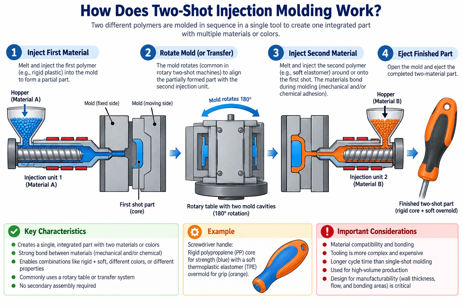
How does two-shot injection molding work? diagram
How to Explain It in an Interview

I would explain the process in four physical steps: inject the first material, rotate or transfer the first shot, inject the second material, then cool and eject the finished part. The important manufacturing point is that the first-shot part becomes the substrate for Shot 2, so its location and geometry must be controlled accurately before the second cavity is filled.

I would then discuss material compatibility and interface design. A strong bond should not be assumed simply because the materials are molded together. Polymer compatibility, interface temperature, surface condition, geometry, and mechanical interlocks can influence adhesion. The tool must also control alignment between the two shots so defects such as flash, mismatch, incomplete coverage, or poor interface definition do not develop.

Tooling and machine selection are production decisions. Two-shot molding generally requires more specialized tooling and equipment than single-shot molding, and the overall cycle includes two injection events plus mold indexing or transfer and cooling. The process is easier to justify when the integrated function, appearance, elimination of secondary assembly, or production volume offsets the additional tooling and equipment complexity.

For validation, I would inspect complete fill, bond quality, flash, short shots, material placement, critical interface dimensions, and visual requirements. If process capability is needed for a critical dimension, I would first confirm that the measurement method is suitable and that the process is stable before interpreting Cp or Cpk. A production control plan can then define the critical material, machine, dimensional, and visual checks. Scrap should also be monitored because a defect in either shot can reject the completed part.

The main conclusion is that two-shot molding is a production process for integrating two materials or colors into one molded component. It works well when the material pair, interface design, tooling alignment, transfer method, process conditions, inspection plan, and production economics are all suitable.

Technical Approach
  1. Define the two materials or colors, required geometry, bonding objective, critical dimensions, cosmetic requirements, production volume, and cost constraints.
  2. Confirm that the material pair and interface design can provide the required chemical adhesion, mechanical interlock, or both.
  3. Design Shot 1 to create a stable core or substrate that can be retained or repositioned accurately.
  4. Select the two-shot architecture, such as a rotary, indexing, or transfer system, that places the first shot at the second injection station.
  5. Design Shot 2 so the second polymer fills the remaining cavity and forms the required overmold or second-color feature without displacing or damaging the first shot.
  6. Establish suitable process conditions for both shots, including material preparation, melt temperature, mold temperature, injection behavior, cooling, indexing or transfer timing, and ejection as appropriate to the selected materials and equipment.
  7. Provide venting, ejection, tooling access, and inspection access that support repeatable production.
  8. Validate fill, interface bonding, flash, dimensional requirements, visual quality, cycle time, and scrap.
  9. After measurement-system suitability and process stability are demonstrated, evaluate capability for critical characteristics and incorporate the required checks into the production control plan.
Practical Insights

Compared with single-shot molding, two-shot molding uses more complex tooling and requires two material-delivery or injection systems plus accurate mold indexing or transfer. Tooling and equipment cost are typically higher, and the total cycle includes additional process steps. The benefit is that two materials or colors can be integrated during molding, which can eliminate a secondary assembly or separate overmolding operation. The economic tradeoff therefore depends on production volume, cycle time, scrap rate, required functionality, tooling investment, and the value of removing downstream operations.

Why Interviewers Ask This

Interviewers want to see whether you understand the complete two-shot molding sequence and can connect the basic process to material compatibility, bonding, tooling design, alignment, cycle time, inspection, manufacturability, scrap, and production-volume tradeoffs rather than describing the process only as two separate injections.

Common interview mistakes

Common mistakes are describing two-shot molding as simply injecting two materials without explaining the mold rotation, indexing, or transfer step; assuming any two polymers will bond chemically; ignoring accurate alignment between the first-shot substrate and the second cavity; forgetting that the first shot must be stable enough for the second molding operation; overlooking venting, flash, shrinkage, interface dimensions, cycle time, and scrap; assuming two-shot molding always reduces cost despite more complex tooling and equipment; and quoting Cp or Cpk before verifying measurement-system suitability and process stability.

Interview tip

Explain the physical sequence first: Shot 1, rotate or transfer, Shot 2, cool, and eject. Then add the manufacturing judgment that makes the answer stronger: material compatibility, bond mechanism, tooling alignment, cycle time, inspection, scrap, and whether the production volume justifies the more complex process.
Interviewer may ask next
How would you validate that the two materials are bonding reliably?

I would first confirm that the selected material pair and interface design support the intended adhesion mechanism. Then I would mold representative parts under controlled conditions and inspect the interface for incomplete coverage, delamination, voids, contamination, flash, and other visible defects. The bond should be evaluated with a test that represents the service loading, such as an application-appropriate peel, pull, or shear test. I would also study sensitivity to relevant molding conditions such as interface temperature, material condition, and timing. Once the measurement method and process are stable, I would define acceptance criteria and include the important bond-related characteristics and process controls in the production control plan.

When might you choose a simpler process instead of two-shot injection molding?

I would consider a simpler process when production volume is too low to justify specialized two-shot tooling and equipment, when the material pair cannot provide reliable bonding, when the geometry can be assembled economically after molding, or when prototype quantities are needed before committing to production tooling. Alternatives could include separately molded parts with mechanical assembly, insert or transfer overmolding, or another appropriate joining method. The decision should compare material compatibility, geometry, tolerance, expected volume, cycle time, scrap, tooling investment, downstream assembly cost, inspection needs, and required functional performance.

52. How do injection-mold slides and lifters differ?ManufacturingMedium

Question Details

Explain how each operates and when each would be used.

Short Interview Answer (30-60 seconds)

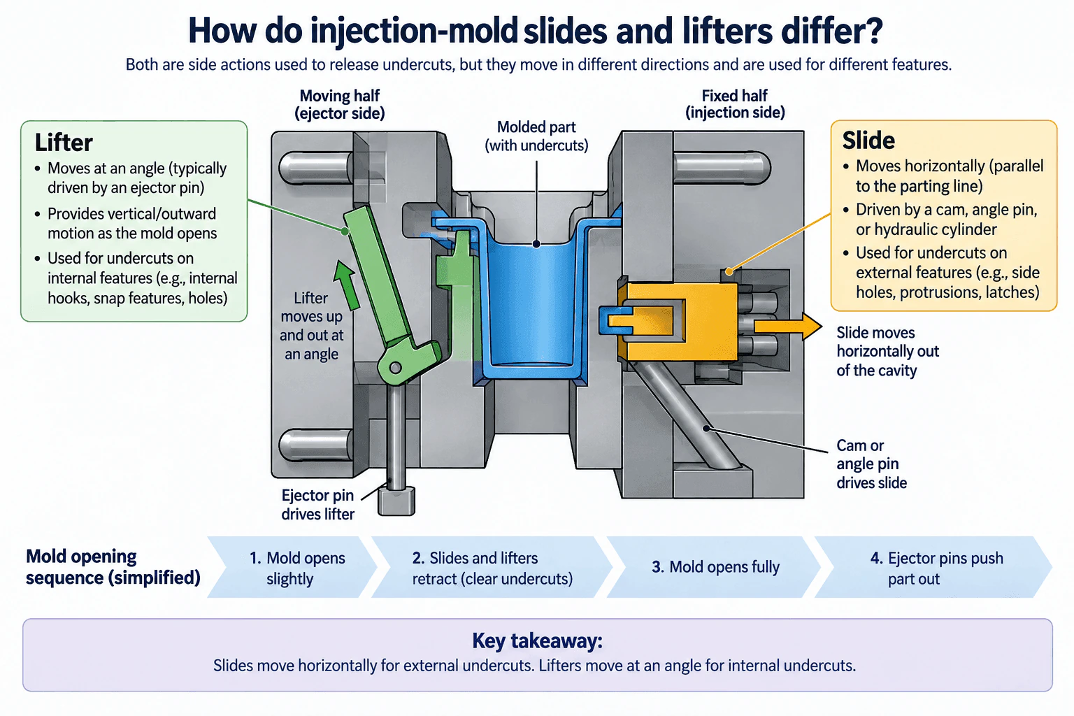
A slide moves sideways, usually parallel to the mold parting line, to clear a lateral undercut before the part is ejected. It may be driven by an angle pin, cam, or hydraulic cylinder. A lifter is an angled component on the ejector side; when the ejector system advances, the lifter moves up and outward, which clears an internal undercut while helping release the part. I would typically use a slide for side holes, protrusions, or latches and a lifter for internal hooks, snap features, or similar geometry that can be released with angled ejector motion.

Detailed Explanation

Slides and lifters solve the same basic injection-molding problem: an undercut prevents the molded part from being released by a simple straight opening of the mold. The main difference is the direction and source of their release motion.

A slide, also called a side action, moves laterally relative to the primary mold-opening direction. In the approved diagram, it moves horizontally out of the cavity, approximately parallel to the parting line. An angle pin or cam can convert mold-opening motion into this lateral travel, and a hydraulic cylinder can also drive the slide. While the mold is closed, the slide forms the required feature. During opening, it withdraws far enough to clear the undercut before final part ejection. Typical applications include side holes, protrusions, latches, and other external or lateral undercuts.

A lifter is an angled member located on the moving, ejector side of the mold. It is driven by the ejector system. As the ejector system advances after the mold has begun opening, the lifter moves upward along its angled path. Because it is inclined, that upward motion also creates an outward component, allowing the lifter head to move away from the internal undercut. Typical applications include internal hooks, snap features, holes, and similar internal geometry that can be released by combined up-and-out motion.

The sequence matters. The mold begins to open, the slide withdraws laterally to clear its side undercut, and the lifter is moved through the ejector-side mechanism so its undercut-forming surface clears the part. Once the mold is fully open and the relevant undercuts have been released, the ejector system completes part removal. The exact timing depends on the mold design, but the basic rule is that no trapped feature should be forced through solid tooling during ejection.

The choice therefore depends on feature geometry and required release direction. If the molding surface must move mainly sideways, a slide is normally the better fit. If an internal feature can be released through a limited angled motion tied to the ejector side, a lifter is often appropriate.

Useful Questions to Ask the Interviewer
  • Is the undercut internal or external, and in what direction must the molding surface move to clear it?
  • How much lateral or angled travel is required before the feature is completely free?
  • Is there enough mold space for the slide body, angle pin, locking arrangement, lifter, and ejector components?
  • Can the molded feature tolerate the lifter's angled motion without dragging, whitening, or deformation?
  • What production volume, cycle-time target, tooling-cost limit, and maintenance requirement apply?
How do injection-mold slides and lifters differ? diagram
How to Explain It in an Interview

I would first identify the undercut and determine the direction and minimum travel required to release it. If the feature needs lateral withdrawal, such as a side hole or external latch, I would normally choose a slide. The slide remains in molding position during injection and then moves horizontally away from the part before ejection. If the undercut is internal and can be released by an angled motion on the ejector side, I would consider a lifter. The ejector system drives the lifter upward, and the lifter's angle produces the outward movement needed to clear the undercut.

I would then check practical mold-design limits: available space, required stroke, slide locking during injection, interference with cooling or ejector components, wear surfaces, part support, and the risk of dragging the molded feature. I would also confirm that the sequence provides complete clearance before the part is pushed out.

For validation, I would review the complete mold-motion sequence, verify that the slide and lifter have enough travel to clear their undercuts, and inspect molded trial parts for drag marks, whitening, deformation, flash, incomplete release, or other evidence that the mechanism is not releasing cleanly. The preferred design is the simplest mechanism that gives adequate clearance, reliable operation, acceptable cycle time, and maintainable tooling.

Technical Approach
  1. Identify the undercut and determine whether it is primarily internal, external, or lateral.
  2. Determine the physical direction and minimum travel required for the molding surface to clear the feature.
  3. Choose a slide when the required withdrawal is predominantly lateral, approximately parallel to the parting line.
  4. Choose a lifter when an internal undercut can be released by combined upward and outward motion from the ejector side.
  5. Select a suitable actuation method: angle pin, cam, or hydraulic cylinder for the slide; ejector-driven angled motion for the lifter.
  6. Check available mold space, required stroke, locking, interference, cooling access, ejector access, wear surfaces, and part support.
  7. Define the release sequence so each undercut is clear before final part removal.
  8. Validate the complete mold cycle and inspect trial parts for dragging, deformation, flash, incomplete release, and repeatability.
Practical Insights

Slides usually need lateral space beside the cavity for the slide body and its drive and locking components. They are well suited to features requiring a direct sideways withdrawal but add moving tooling, wear surfaces, and sequencing requirements. Lifters can be more compact for suitable internal undercuts because their release motion is integrated with the ejector side, but their angled movement is limited by mold geometry and can create drag if the feature or travel is poorly designed. For both mechanisms, greater stroke, tighter packaging, more moving interfaces, and difficult maintenance access can increase tooling cost, cycle risk, wear, and scrap.

Why Interviewers Ask This

Interviewers want to see whether you understand how injection-mold tooling releases geometry that would otherwise trap the part. They are evaluating whether you can relate the location and required release direction of an undercut to the correct mechanism while also considering tooling space, stroke, sequencing, reliability, part damage, cycle time, and maintenance.

Common interview mistakes

A common mistake is saying that slides are always for external features and lifters are always for internal features without first considering the actual release direction. The required motion is the more important design criterion. Another mistake is describing a lifter as moving only vertically; because it is angled, ejector-driven upward motion also creates outward movement. It is also incorrect to ignore sequence and clearance: the undercut-forming surface must move far enough to release the feature before the part is forced out. Other mistakes include overlooking mold space, stroke, locking, wear, cooling access, ejector interference, maintenance access, and possible part drag.

Interview tip

Start with the motion difference: a slide withdraws laterally, while a lifter moves up and outward along an angled ejector-driven path. Then connect each motion to the undercut geometry it can release. Finish by mentioning clearance, stroke, sequence, mold space, part damage, cycle time, and tooling reliability. That demonstrates both conceptual understanding and practical manufacturing judgment.

Interviewer may ask next
How would you verify that a lifter will release an internal undercut without damaging the part?

I would determine the lateral clearance required by the undercut and confirm that the outward component of the lifter's motion exceeds that requirement over the available ejector stroke. I would also review the lifter head geometry, contact surfaces, part support, interference, and the full motion path. During mold trials, I would inspect for drag marks, whitening, deformation, incomplete release, or the part remaining caught on the lifter. The lifter should demonstrate repeatable clearance before the tooling is accepted for production.

What could make you choose a hydraulic slide instead of an angle-pin-driven slide?

A hydraulic slide can be useful when the side action needs independently controlled timing or stroke, when the required movement is difficult to obtain directly from mold opening, or when mold packaging makes a conventional angle-pin arrangement impractical. The tradeoff is greater complexity because the design adds an actuator, hydraulic connections, controls, maintenance requirements, and sequencing considerations. I would choose it only when those benefits justify the additional tooling and operating complexity.

53. What three manufacturing methods can produce foam parts?ManufacturingEasy

Question Details

The parts are cushions for wearable consumer hardware.

Short Interview Answer (30-60 seconds)

Three common methods are foam molding, die cutting, and CNC or contour cutting. Foam molding is useful for repeatable three-dimensional cushions and becomes more attractive when production volume justifies dedicated tooling. Die cutting is efficient for parts made from relatively constant-thickness foam sheet. CNC or contour cutting is flexible for prototypes, lower volumes, and designs that may still change. For a wearable consumer-hardware cushion, I would choose among them based on foam material, geometry, tolerances, production volume, tooling investment, surface quality, and cycle time.

Detailed Explanation

Foam cushions for wearable consumer hardware can be manufactured in several ways, but three practical choices are foam molding, die cutting, and CNC or contour cutting. The right method depends on the foam material, whether the part is flat or three-dimensional, production volume, tolerance requirements, surface and edge quality, tooling budget, cycle time, and scrap.

  1. Foam molding: The foam is formed in dedicated tooling so the process can produce a repeatable three-dimensional shape. Depending on the particular foam system, material may be introduced into the mold and then expand, cure, or otherwise form to the tool surfaces. Molding is especially useful when the cushion needs contoured surfaces, varying thickness, or geometry that would be difficult to create from flat sheet stock. Its main tradeoff is the cost and lead time of dedicated tooling, so it is generally more attractive when production volume is sufficient to justify that investment.
  1. Die cutting: A cutting die produces the required outline from foam sheet or laminated foam stock. This works well when the cushion is primarily two-dimensional and has a relatively uniform starting thickness. Once the die is available, the process can provide short cycle times and good repeatability for high-volume production. Its limitation is that it does not naturally create deeply contoured three-dimensional geometry or continuously varying thickness.
  1. CNC or contour cutting: Programmable cutting equipment produces the shape from foam stock using a process appropriate for the material, such as a blade, knife, or other suitable cutting tool. It requires less dedicated shape tooling than molding or die cutting, which makes it useful for prototypes, engineering builds, lower-volume production, and designs that may still change. The tradeoff is that each part consumes machine time, so high-volume unit cost and cycle time may be less favorable than a mature die-cutting or molding process.

For a wearable cushion, I would also consider the interfaces that affect fit, comfort, attachment, and appearance. Important manufacturing characteristics may include overall profile, local thickness, mating surfaces, cut-edge condition, molded surface condition, and features used for bonding or assembly. Those characteristics should drive both process selection and inspection planning.

Useful Questions to Ask the Interviewer
  • What foam material or foam family is being considered?
  • Is the cushion primarily a constant-thickness sheet part, or does it need a three-dimensional contour or varying thickness?
  • What production volume is expected?
  • Which dimensions or surfaces are critical to fit, comfort, appearance, or assembly?
  • Are adhesive films, fabric laminates, skins, or other secondary materials part of the cushion construction?
  • What edge quality, molded-surface quality, and cosmetic requirements apply?
  • How frequently is the geometry expected to change during development?
How to Explain It in an Interview

I would first classify the geometry. If the cushion is mainly a constant-thickness profile cut from sheet stock, die cutting is a strong production candidate because it can make parts quickly and repeatably once the die is available. If the cushion requires a true three-dimensional contour or varying thickness, molding is a stronger candidate because the required shape can be created directly by the tooling. If the design is still changing, production volume is low, or dedicated tooling is not yet justified, CNC or contour cutting provides greater flexibility.

I would then compare those choices using material compatibility, dimensional capability, tooling investment, cycle time, scrap, surface and edge quality, and production volume. For example, die cutting can create nesting scrap around the part profile. Molding requires greater tooling investment but can efficiently create complex three-dimensional shapes at production scale. CNC or contour cutting reduces dedicated tooling commitment but can require more processing time per part.

Before production release, I would manufacture representative parts using the intended foam, tooling, and process settings. I would identify the critical characteristics, select measurement methods suitable for compliant foam, and check whether the process repeatedly meets those requirements. If process capability metrics such as Cp or Cpk are needed, I would first verify that the measurement system is adequate and that the manufacturing process is stable. The final process should therefore be selected not simply because it can make foam, but because it can repeatedly make the required cushion at the necessary quality, production rate, and cost.

Technical Approach
  1. Identify the foam material or material family and determine which molding and cutting processes are compatible with it.
  2. Classify the geometry as primarily constant-thickness sheet, cuttable three-dimensional stock, or a shape that is better formed directly in tooling.
  3. Identify critical characteristics such as thickness, perimeter, mating surfaces, edge condition, molded surface condition, and attachment features.
  4. Determine whether the need is prototype, low-volume, or production-scale manufacturing.
  5. Compare foam molding, die cutting, and CNC or contour cutting for tooling investment, cycle time, scrap, dimensional repeatability, surface quality, and design flexibility.
  6. Select the process that best matches the material, geometry, volume, and quality requirements.
  7. Produce representative parts with the intended material and process.
  8. Inspect critical characteristics using methods and fixtures appropriate for compliant foam.
  9. Establish a control plan for important production characteristics.
  10. If capability analysis is required, verify measurement adequacy and process stability before interpreting Cp or Cpk.
Practical Insights

Foam molding usually requires the largest dedicated tooling investment, but it can efficiently produce repeatable three-dimensional parts when volume is high enough. Die cutting also requires tooling, but once the die is made it can provide short cycle times for flat or constant-thickness parts; nesting efficiency and sheet scrap affect material cost. CNC or contour cutting requires less dedicated shape tooling and makes design changes easier, but each part consumes machine time, so it may become less economical at high production volume. Tighter tolerances, complex contours, laminates, cosmetic requirements, and difficult-to-measure soft features increase manufacturing and inspection effort for any of the three methods.

Why Interviewers Ask This

The interviewer is testing whether I can identify practical foam manufacturing processes and select among them based on material, geometry, tolerance needs, production volume, tooling cost, cycle time, scrap, and required surface or edge quality. For wearable cushions, the interviewer also wants to see whether I distinguish flexible prototype processes from scalable production processes.

Common interview mistakes

Common mistakes include listing manufacturing methods without relating them to geometry or production volume, assuming all foam materials can be processed the same way, and choosing molding automatically even when a simple die-cut sheet part would be more economical. Another mistake is choosing CNC cutting only because it avoids dedicated tooling while ignoring its cycle-time and unit-cost disadvantages at high volume. It is also incorrect to quote Cp or Cpk as proof of process capability without first confirming a suitable measurement system and a stable process.

Interview tip

Name the three methods first, then give the decision boundary between them: die cutting for mostly sheet-like parts, molding for repeatable three-dimensional contours, and CNC or contour cutting when flexibility or lower tooling commitment is important. That demonstrates manufacturing judgment rather than simply listing processes.

Interviewer may ask next
How would you validate the selected foam manufacturing process before full production?

I would manufacture representative parts using the intended foam, tooling, and process settings, then inspect the critical characteristics that affect fit, assembly, appearance, and cushion function. Because foam is compliant, I would also make sure the measurement method and fixture do not distort the part enough to invalidate the result. I would review edge or molded-surface quality, scrap, cycle time, and any secondary operations such as lamination or adhesive application. Once the process is stable and the measurement system is suitable, production data can be used to assess repeatability and, where appropriate, process capability. The important characteristics would then be included in the production control plan.

What would change if the cushion evolved from a flat constant-thickness design to a deeply contoured three-dimensional design?

The preferred process would likely shift. A flat, constant-thickness cushion is naturally suited to a sheet process such as die cutting and may also be practical to CNC or contour cut during development. A deeply contoured three-dimensional cushion is much harder to produce efficiently with a simple cutting die, so molding becomes a stronger production candidate. CNC or contour processing may still be useful for prototypes or low volumes if the geometry and material permit it, but at higher volume I would compare its per-part processing time with the tooling investment and repeatability advantages of molding.

54. When should a hole be counterbored rather than countersunk?ManufacturingEasy

Short Interview Answer (30-60 seconds)

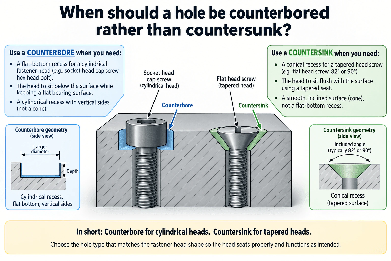
Use a counterbore when the fastener has a cylindrical head, such as a socket-head cap screw or suitable hex-head fastener, and you need a larger-diameter cylindrical recess with vertical sides and a flat bottom. This lets the head seat on a flat bearing surface and, when the recess is deep enough, sit below the surrounding surface. Use a countersink for a tapered flat-head screw that must seat against a conical surface, commonly so the top of the head is flush with the part surface. The basic rule is to match the recess shape to the fastener-head shape.

Detailed Explanation

A counterbore and a countersink both enlarge the entrance of a hole, but they create different seating geometries.

A counterbore creates a larger-diameter cylindrical recess with vertical sides and a flat bottom. It is appropriate for a cylindrical fastener head, such as a socket-head cap screw, when the head needs a flat bearing surface. The counterbore can also recess the head below the surrounding surface when its diameter and depth provide the required clearance.

A countersink creates a conical recess. It is appropriate for a tapered flat-head screw whose underside is designed to seat against an inclined surface. The countersink included angle must match the selected fastener geometry. Common flat-head fastener systems may use angles such as 82° or 90°, so the angle should be taken from the actual fastener specification rather than assumed.

The selection therefore starts with two questions: what shape is the fastener head, and where should the head finish relative to the part surface? A cylindrical head needing a flat-bottom seat points to a counterbore. A tapered flat head needing a conical seat points to a countersink.

Useful Questions to Ask the Interviewer
  • What fastener type and head geometry are specified?
  • Should the fastener head finish below, flush with, or above the surrounding surface?
  • Is a flat bearing surface required under the head?
  • What counterbore diameter and depth, or countersink angle and depth, are specified?
  • Is there enough material thickness for the recess without creating an excessively thin remaining section?
  • What machining and inspection access is available?
When should a hole be counterbored rather than countersunk? diagram
How to Explain It in an Interview

I would first identify the fastener-head geometry. For a cylindrical head such as a socket-head cap screw, I would normally choose a counterbore because it produces a cylindrical recess with vertical sides and a flat bottom. That gives the head a flat seating surface and can place the complete head below the surrounding surface when sufficient depth is provided.

For a tapered flat-head screw, I would choose a countersink because it creates the matching conical seat. The included angle of the countersink must correspond to the fastener geometry so the tapered underside contacts the intended seating surface correctly. This is commonly used when the screw head is intended to finish flush with the surface.

From a manufacturing standpoint, I would also check available material thickness, tooling access, recess dimensions, tolerance requirements, and inspection access. A counterbore requires control of its larger diameter and depth, while a countersink requires control of its conical geometry and resulting head seating condition. I would verify the finished feature with appropriate dimensional inspection and, where useful, confirm the actual fastener seats without unintended interference.

The final rule is straightforward: choose a counterbore for a cylindrical fastener head that needs a flat-bottom cylindrical recess, and choose a countersink for a tapered flat-head fastener that needs a conical seating surface.

Technical Approach
  1. Identify the specified fastener and its head geometry.
  2. Determine whether the head must finish below, flush with, or above the surrounding surface.
  3. If the head is cylindrical and needs a flat bearing surface, choose a counterbore.
  4. If the head is tapered and designed to seat on an inclined surface, choose a countersink.
  5. For a counterbore, determine the required larger diameter and depth from the fastener and design requirements.
  6. For a countersink, match the included angle and depth to the selected fastener geometry.
  7. Check material thickness, tooling access, tolerances, and inspection access.
  8. Verify that the manufactured recess lets the fastener seat on its intended bearing surface without interference.
Practical Insights

A counterbore usually removes more material because it forms a larger cylindrical pocket to a controlled depth, so it can increase machining time and may be more restrictive in thin sections. A countersink removes material in a conical shape and is often simpler, but its included angle and depth still need to match the fastener so the head seats correctly. In production, either feature should be selected from functional geometry first, then checked for tooling access, cycle time, inspection practicality, and the amount of material remaining around and beneath the recess.

Why Interviewers Ask This

Interviewers want to see whether you can select hole geometry from the fastener-head geometry and required seating condition. The key judgment is recognizing that a counterbore provides a cylindrical, flat-bottom recess for a cylindrical head, while a countersink provides a conical seating surface for a tapered flat-head fastener.

Common interview mistakes

Common mistakes include selecting the feature only from appearance instead of fastener-head geometry; using a countersink for a cylindrical head; using a counterbore for a tapered flat head; assuming every countersunk fastener uses the same included angle; making a counterbore too shallow for the required recessed-head condition; failing to leave enough material beneath or around the recess; and specifying dimensions without considering tooling and inspection access.

Interview tip

Lead with the geometry rule: a counterbore is a cylindrical, flat-bottom recess for a cylindrical fastener head, while a countersink is a conical recess for a tapered flat-head fastener. Then mention the required head position, correct seating surface, material thickness, tooling, and inspection. That demonstrates both design understanding and manufacturing judgment.

Interviewer may ask next
How would you verify that a counterbore is manufactured correctly?

I would inspect the counterbore diameter and depth because those dimensions control clearance and the final position of the cylindrical fastener head. I would also verify the location of the underlying hole when its position is functionally important, check that the recess has the intended flat seating surface, and confirm that the specified fastener seats without interference. The inspection method would depend on the tolerance and accessibility of the feature.

What changes if the requirement is for the fastener head to be flush with the surface?

The fastener-head geometry still determines the recess type. A tapered flat-head screw normally uses a countersink so its conical underside seats against the matching tapered surface and the top of the head can finish flush. A cylindrical-head screw would instead need a counterbore if it must be recessed, because a countersink does not provide the flat-bottom seating surface required by a cylindrical head.

55. What DFMA issues arise when a machined component changes from aluminum to steel?ManufacturingHard

Question Details

Consider design for manufacturing and assembly for the material substitution.

Short Interview Answer (30-60 seconds)

Changing a machined component from aluminum to steel requires a DFMA review even if the geometry stays the same. The steel grade may need different tools, cutting speeds, feeds, coolant, workholding, and deburring, and the higher cutting forces can make thin walls, deep pockets, or long tool reaches less robust. The finished part will also generally be heavier, which can affect handling and assembly. I would recheck tolerances, surface finish, threads and fits, joining, corrosion protection, heat treatment if applicable, inspection access, cycle time, and tooling cost. Then I would build representative parts with the intended production process and verify critical characteristics and process capability before release.

Detailed Explanation

Changing from aluminum to steel is not just a drawing-material update. The substitution can change how the component is machined, fixtured, inspected, handled, assembled, protected, and produced economically. A good DFMA review first identifies why the material is changing and then checks whether the existing geometry and production route still make sense for the selected steel grade.

Useful Questions to Ask the Interviewer
  1. What is driving the material change: strength, stiffness, wear, temperature capability, cost, availability, or another requirement?
  2. What aluminum grade and steel grade or condition are involved?
  3. Must the geometry, tolerances, surface finishes, and interfaces remain unchanged?
  4. What is the expected production volume, and is the current process for prototypes or sustained production?
  5. Which dimensions and interfaces are critical to function or assembly?
  6. Are there limits on finished-part mass, manual handling, or automated assembly equipment?
  7. Are heat treatment, coating, plating, painting, or other corrosion-control processes required?
  8. What mating materials, fasteners, bearings, seals, or welded components interface with the part?
How to Explain It in an Interview

I would review the substitution in five connected areas: machining, geometry and tolerances, assembly, secondary processing, and production validation.

First, I would revisit the machining process. A toolpath or parameter set developed for aluminum should not automatically be reused for steel. The proper cutting speed, feed, depth of cut, cutter or insert grade, coolant strategy, chip control, and tool-change interval depend on the specific steel grade, machine, tooling, and operation. Machining forces and heat can be higher, so I would check spindle power, tool rigidity, workholding, fixture stiffness, chip evacuation, and the risk of chatter or deflection. Cycle time and tool consumption may also increase, changing total manufacturing cost.

Second, I would review the geometry for manufacturability. Features that were economical in aluminum, such as deep pockets, thin walls, small internal radii, long slender features, deep drilled holes, or long tool reaches, may become slower or less robust to machine in steel. Higher cutting forces can increase deflection and vibration. If function permits, I would consider larger internal radii, shorter tool reach, thicker or better-supported sections, reduced pocket depth, fewer setups, or other geometry changes that improve rigidity and tool access.

Third, I would recheck tolerances and surface finishes based on function rather than copying the aluminum drawing unchanged. Critical dimensions should be matched to a machining process that can produce them repeatedly and to an inspection method with suitable access and measurement capability. I would not claim that a process is capable simply because the machine specification appears accurate. For production characteristics, Cp or Cpk should only be interpreted after the process is sufficiently stable and suitable measurement data have been collected.

Fourth, I would review assembly consequences. With unchanged geometry, a steel component will generally have greater mass than an aluminum component, so manual handling, robotic payload, fixture loading, assembly ergonomics, and loads on adjacent components may change. I would also recheck threaded features, inserts, fastener strategy, torque requirements, press or interference fits, bearing seats, welds, brazed joints, and other joining methods against the actual material grades and conditions rather than assuming the aluminum design transfers directly.

Material interfaces also need attention. If the steel component contacts aluminum or another dissimilar material, the service environment and corrosion risk should be reviewed. Depending on the application, corrosion control may involve an appropriate coating, plating, paint system, material pairing, sealing, drainage, or electrical isolation. The exact treatment should be selected from the actual materials, environment, dimensional requirements, and applicable specifications rather than assumed generically.

Heat treatment can introduce another manufacturing sequence. If the selected steel requires heat treatment to achieve the intended properties, I would assess possible distortion, scale, hardness variation, machining difficulty after treatment, and the effect on final tolerances. Where appropriate, the route may include rough machining before heat treatment and selected finish machining or grinding afterward, but that sequence must be validated for the actual part and material.

Next, I would review tooling and inspection. A fixture used successfully for aluminum may not provide enough rigidity for the cutting forces associated with the steel process. The heavier workpiece may also change loading, clamping, or automation requirements. Inspection access should still be adequate after any coating or heat-treatment operation. Critical characteristics should be connected to suitable inspection methods and, for production, to an appropriate control plan.

Finally, I would compare the full production economics rather than only the raw material price. Relevant factors include stock form, purchased material cost, machining time, tool wear, setup time, fixture changes, secondary finishing, heat treatment if required, inspection effort, scrap risk, handling, assembly time, and production volume. At higher volumes, it may be worth redesigning the geometry to remove less material or evaluating a suitable near-net-shape starting process such as forging or casting before finish machining.

Before release, I would manufacture representative steel parts using the intended production route. I would verify dimensions, surface requirements, assembly interfaces, tooling behavior, fixture stability, and any finishing or heat-treatment effects. I would then confirm that critical characteristics are under control and, where capability indices are appropriate, use actual data from a stable measured process. The final decision should therefore consider function, manufacturability, assembly, quality evidence, and total cost rather than assuming that a material substitution leaves the rest of the process unchanged.

Technical Approach
  1. Define why the material is changing and identify the exact aluminum and steel grades and conditions.
  2. Separate functional requirements from legacy manufacturing choices, including critical dimensions, finishes, interfaces, and loads.
  3. Review machinability and update cutting tools, cutting parameters, coolant strategy, chip control, workholding, and machine-capability requirements as needed.
  4. Review geometry for deep pockets, thin walls, small radii, long tool reach, drilled features, and other features that may become less robust or more expensive in steel.
  5. Reassess tolerances and surface finishes according to function and realistic process capability.
  6. Review assembly effects including increased mass, handling, fasteners, threads, fits, joining methods, and mating components.
  7. Determine whether corrosion protection or heat treatment is required and account for those operations in the dimensional and manufacturing sequence.
  8. Recheck fixtures, gauges, inspection access, cycle time, tool consumption, scrap risk, and total manufacturing cost.
  9. Build representative parts using the intended production process and verify dimensional, surface, and assembly requirements.
  10. Establish suitable production controls and demonstrate capability for critical characteristics using actual stable-process measurement data where capability analysis is appropriate.
Practical Insights

The main tradeoff is that steel may provide the functional properties that motivated the change while making machining and assembly more demanding. Cutting may require different tooling and parameters, greater forces can make flexible features harder to machine consistently, and cycle time or tool consumption may increase. The completed part will also generally be heavier for the same geometry, which can affect handling and assembly. Secondary operations such as heat treatment or corrosion protection can add cost, lead time, inspection steps, and dimensional variation. Good DFMA therefore removes unnecessary machining and unnecessary tolerance while protecting the features that are truly required for function.

Why Interviewers Ask This

This question tests whether the candidate recognizes that a material substitution is also a manufacturing and assembly change. The interviewer is evaluating judgment about machinability, tooling, process parameters, geometry, tolerances, fixturing, component mass, joining, corrosion protection, inspection, process capability, cycle time, scrap, and total production cost.

Common interview mistakes

Common mistakes include treating the change as only a material callout revision; reusing aluminum cutting parameters without validation; assuming the same fixture is automatically adequate; retaining unnecessarily tight tolerances; ignoring increased component mass and assembly handling; overlooking changes to threads, fits, joining, corrosion protection, or heat-treatment sequence; comparing only raw material prices instead of total manufacturing cost; and reporting Cp or Cpk without first having a sufficiently stable process and suitable measurement data.

Interview tip

Structure the answer around the complete production path: machine it, hold it, inspect it, protect it, assemble it, and validate it. Make clear that the exact steel grade, geometry, volume, interfaces, and functional requirements determine the final process. That demonstrates stronger DFMA judgment than simply saying that steel is harder to machine.

Interviewer may ask next
How would you validate that the existing tolerances can still be produced reliably after changing to steel?

I would first identify which dimensions are actually critical to function and confirm that the inspection method is suitable. Then I would manufacture representative parts using the intended steel grade, tooling, fixture, machine, process sequence, and secondary operations. I would check for instability caused by factors such as tool wear, thermal effects, deflection, fixture movement, or heat-treatment distortion. After establishing a sufficiently stable process and suitable measurement system, I would collect production-representative data for the critical characteristics and evaluate capability, including Cp or Cpk where appropriate. If capability is inadequate, I would improve the process, tooling, fixturing, or design, or relax a nonessential tolerance if function permits.

What changes if production volume increases significantly after the material is changed to steel?

At higher volume, recurring cycle time, tool consumption, setup losses, inspection effort, handling, and scrap have a larger economic impact. I would look more aggressively for DFMA improvements such as reducing removed material, eliminating setups, standardizing tools, increasing internal radii, improving tool access, and using dedicated production fixtures. I would also evaluate whether a suitable near-net-shape starting process such as forging or casting followed by finish machining could reduce total cost. The choice would depend on geometry, required material properties, tolerances, production quantity, tooling investment, and demonstrated process capability.

56. Describe a complex manufacturing problem you solved.ManufacturingHard

Question Details

Use an example from your manufacturing experience.

Short Interview Answer (30-60 seconds)

A strong example, if it matches your experience, is a machined feature that repeatedly failed its final dimensional requirement after a downstream process. I would explain that I first contained the problem, verified the measurement method, and separated variation by process step, machine, fixture, tool condition, and batch where relevant. The investigation showed that machining was repeatable, but a later heat-treatment operation shifted the critical dimension and left too little tolerance margin. I corrected the manufacturing strategy by changing the process target or sequence, strengthening fixture and tool controls, and defining a control plan for the critical characteristic. I then verified process stability before relying on capability measures such as Cp or Cpk. The important result was not simply producing acceptable parts again; it was establishing a repeatable process and preventing recurrence.

Detailed Explanation

A complex manufacturing problem should be explained as an engineering investigation rather than simply as a story about finding a defective part. A strong example shows how you moved from a production symptom to verified causes, selected a corrective action based on evidence, and then demonstrated that the corrected process was stable enough for production.

The example below is hypothetical. In an interview, I would replace the assumed details with my actual manufacturing experience, dimensions, processes, responsibilities, and measured results.

Suppose a production component contains a precision-machined bore that must remain within its drawing tolerance after machining and a later heat-treatment operation. Final inspection begins finding an unacceptable number of bores outside specification. I would not immediately adjust the machine offset because the dimensional error could come from several sources, including tool wear, fixture distortion, machine variation, heat-treatment distortion, or measurement error.

My first step would be containment. I would identify potentially affected production, prevent questionable parts from progressing unnoticed, and establish an appropriate temporary inspection method for the critical bore. Containment protects production while the root cause is investigated, but it is not the permanent corrective action.

Next, I would verify the measurement system. I would confirm that the gauge or measurement equipment, inspection fixture, datum setup, measurement procedure, and operator technique are suitable for the tolerance being evaluated. If the measurement system cannot reliably distinguish part-to-part variation from measurement variation, any process-capability conclusion would be questionable.

I would then map the complete manufacturing sequence and identify the operations capable of changing the bore. Useful measurements might be taken after rough machining, after finish machining, and after heat treatment. I would stratify the data using factors that are actually relevant, such as machine, fixture, tool condition, material lot, heat-treatment batch, or production time. This helps separate variation created during machining from variation introduced by downstream processing.

Assume the evidence shows that the bore is stable and repeatable immediately after finish machining but shifts after heat treatment. That would indicate that the machining operation itself is not the complete root cause. The process is producing the bore near its intended pre-treatment value, but the downstream thermal process changes the dimension enough that the finished part no longer has adequate tolerance margin.

At that point, I would generate corrective options using design-for-manufacturability and production-process reasoning. Options could include changing the pre-heat-treatment machining target, leaving controlled stock for a finishing operation after heat treatment, modifying the manufacturing sequence, improving fixturing, reducing variation in the thermal process, or involving design engineering if evidence suggests the specified tolerance is substantially tighter than the functional requirement. Manufacturing should not change an engineering drawing requirement without the appropriate design approval.

The best corrective action depends on the behavior of the process. If the heat-treatment shift is predictable, sufficiently stable, and physically understood, changing the pre-treatment machining target may recover tolerance margin without adding another manufacturing operation. If the distortion is too variable, machining or finishing the bore after heat treatment may be more robust, although it can increase handling, tooling cost, inspection requirements, and cycle time. I would compare these alternatives using process evidence rather than selecting the least expensive option automatically.

After implementing the selected correction under controlled conditions, I would verify statistical stability before interpreting capability. Cp compares the natural process spread with the specification width and indicates potential capability when the process is stable. Cpk also accounts for process centering relative to the specification limits. A process can therefore have an acceptable Cp but a poorer Cpk if its mean is shifted toward one specification limit. Neither value should be treated as reliable evidence of long-term capability if the process is unstable or the measurement system is inadequate.

I would then validate the corrected process across representative production conditions. That could include normal tooling life, relevant machines or fixtures, operators or shifts where applicable, and representative downstream batches. I would look for evidence that the characteristic remains stable and that the process can consistently meet the drawing requirement rather than relying on a short run of acceptable parts.

Finally, I would update the control plan for the critical characteristic. The control plan should define what is measured, where it is measured, the inspection method, the appropriate sampling or verification approach, process-monitoring requirements, and the reaction plan if the characteristic begins moving toward a specification limit. Tooling and fixture checks should also be included where they are relevant to the identified failure mechanism.

The main lesson is that a difficult manufacturing problem is rarely solved by changing one machine parameter. The stronger solution connects the drawing requirement, measurement system, manufacturing sequence, physical root cause, process stability, capability, tooling, inspection, scrap risk, and cycle-time consequences.

Useful Questions to Ask the Interviewer
  • Would you like me to focus more on the root-cause investigation or on the production changes I implemented?
  • Would you like quantitative detail on tolerance, scrap, cycle time, or process capability from my example?
  • Should I explain how I validated the corrective action before full production release?
  • Would you like me to discuss how manufacturing, quality, and design responsibilities were coordinated?
How to Explain It in an Interview

Start with the production problem and its impact in one or two sentences. Then explain containment, measurement verification, and how you separated possible causes. State the root cause only after describing the evidence that supported it. Explain the corrective options you considered, why you selected one, and what tradeoff you accepted. Finish with how you validated process stability, capability, and the control plan. Use your actual tolerance, Cpk, scrap, cost, or cycle-time numbers only when they were genuinely measured; otherwise describe the outcome without inventing metrics.

Technical Approach
  1. Define the failed manufacturing requirement and its production or functional impact.
  2. Contain potentially affected production while preserving evidence for investigation.
  3. Verify that the measurement system, datum setup, inspection method, and inspection access are suitable for the characteristic.
  4. Map the complete manufacturing sequence and identify every operation capable of changing the characteristic.
  5. Collect and stratify data using relevant factors such as process step, machine, fixture, tool condition, material lot, or downstream batch.
  6. Determine whether the variation is associated with a specific cause or with the normal behavior of the process.
  7. Identify the physical root cause rather than correcting only the final symptom.
  8. Develop corrective options and compare their effects on tolerance capability, tooling, inspection, cycle time, scrap, and cost.
  9. Implement the technically justified corrective action under controlled conditions.
  10. Confirm process stability before interpreting Cp, Cpk, or similar capability measures.
  11. Validate the corrected process across representative production conditions.
  12. Update the control plan, inspection strategy, tooling or fixture checks, reaction plan, and applicable manufacturing documentation to prevent recurrence.
Practical Insights

The main tradeoff is usually between process robustness and production cost. Adding a finishing operation after heat treatment can improve dimensional control but may increase handling, tooling, inspection, and cycle time. Changing only a machine target may be less expensive, but it is appropriate only when the downstream dimensional shift is sufficiently predictable and stable. Increasing final inspection can help contain defects, but inspection alone does not improve the underlying process. Capability measures are useful only after the measurement system is suitable and the process is reasonably stable. The strongest production solution therefore balances repeatability, tolerance capability, tooling, fixture control, inspection access, scrap risk, cycle time, and cost.

Why Interviewers Ask This

Interviewers are evaluating whether you can investigate a difficult production problem systematically, distinguish symptoms from root causes, connect drawing tolerances to real manufacturing capability, use manufacturing and quality evidence correctly, and implement a solution without creating unacceptable cost, scrap, cycle-time, tooling, or inspection problems.

Common interview mistakes

Common mistakes include jumping directly to a machine adjustment without proving the root cause, calculating Cpk from an unstable process, ignoring measurement-system variation, treating final inspection as the permanent corrective action, changing several process variables at once so the true cause remains unclear, overlooking fixture or tool-condition effects, ignoring downstream processes such as heat treatment, and inventing numerical improvements that were never measured.

Interview tip

Use one real manufacturing problem and make your own contribution clear. Structure the answer as problem, containment, evidence, root cause, corrective action, tradeoff, and validation. Explain why the problem was difficult and how your evidence changed the decision. If you have verified values for tolerance, Cp, Cpk, scrap, cycle time, or cost, include them because they strengthen the example. Do not invent metrics or claim ownership of work performed by someone else.

Interviewer may ask next
How would you prove that the corrective action really solved the problem rather than temporarily moving the process back inside specification?

I would verify both process stability and capability. First, I would confirm that the measurement system is suitable and collect production data across representative operating conditions. I would use statistical process control or another appropriate stability assessment to look for special-cause behavior and changes over time. Only after the process appears stable would I evaluate capability relative to the specification limits using appropriate measures such as Cp and Cpk. I would also review actual nonconformance trends and confirm that the control plan detects meaningful drift. A short run of acceptable parts would not be enough because it might not include the normal sources of production variation.

What would you do if adding a post-heat-treatment finishing operation solved the tolerance problem but increased cycle time too much?

I would compare alternative ways to achieve the required capability before accepting the additional operation permanently. I would investigate whether heat-treatment variation or distortion could be reduced, whether fixturing could be improved, whether a controlled pre-treatment machining target could compensate for a repeatable shift, and whether the tolerance reflects the true functional requirement. Any drawing or tolerance change would require appropriate design approval. I would compare the alternatives using process stability, capability, scrap risk, tooling requirements, inspection needs, and cycle time. If post-treatment finishing remained the only robust method, I would optimize that operation rather than choose a faster process that could not reliably meet the requirement.

57. What is finite element analysis (FEA)?Simulation And Engineering AnalysisEasy

Short Interview Answer (30-60 seconds)

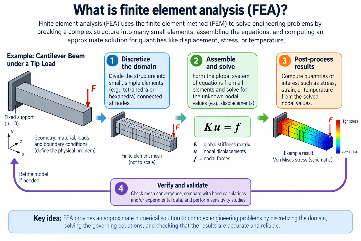
Finite element analysis, or FEA, is a numerical method used to approximate how structures and other physical systems respond to loads and operating conditions. The geometry is divided into many small finite elements connected at nodes. Equations describing the behavior of those elements are assembled into a global system, such as K u = f for a linear structural problem, and solved for unknown nodal quantities such as displacement. Engineers then calculate results such as stress, strain, or temperature and verify that the solution is sufficiently mesh-independent and consistent with hand calculations or experimental data.

Detailed Explanation

Finite element analysis, or FEA, is a numerical technique for solving engineering problems that may be difficult or impossible to solve exactly with simple closed-form equations. Instead of treating the entire structure or domain as one continuous object, FEA divides it into many smaller pieces called finite elements. The elements are connected at nodes, and mathematical equations describe how each element behaves.

For a simple linear structural problem, the assembled system can be written as K u = f, where K is the global stiffness matrix, u is the vector of unknown nodal displacements, and f is the applied nodal force vector. Once the nodal displacements are solved, quantities such as strain and stress can be calculated from the solution. Other finite element formulations can solve for quantities such as temperature, vibration modes, or buckling behavior using governing equations appropriate to those physics.

A useful example is a cantilever beam fixed at one end with a downward load at the free end. The physical problem first defines the geometry, material behavior, load, and fixed boundary condition. The beam is then discretized into finite elements. The element equations are assembled into the global system and solved, and the displacement and stress fields are post-processed. For the ideal tip-loaded cantilever shown in the diagram, the nominal bending moment is greatest at the fixed root and decreases toward zero at the free end, so the nominal bending stress follows the same trend. The displayed stress contour is schematic rather than a numerical simulation result.

The important point is that an FEA result is an approximation. A visually smooth contour or a solver message saying that the equations converged does not by itself prove that the engineering result is correct. The engineer must check the model assumptions, element type, mesh quality, boundary conditions, loads, contacts, material model, and relevant solver settings. Mesh refinement should be used to determine whether quantities important to the engineering decision are converging. Results should also be compared with a hand calculation, analytical solution, known limiting case, or experimental data when available.

Numerical verification and physical validation are different. Verification asks whether the mathematical model has been solved correctly, for example by checking mesh convergence, equilibrium or conservation, numerical convergence, and sensitivity to modeling choices. Validation asks whether the model represents the real physical system adequately, usually by comparing predictions with experimental measurements or other physical evidence.

Engineers must also interpret local peaks carefully. For example, an idealized point load, sharp re-entrant corner, or perfectly rigid constraint can produce a stress singularity or a mesh-sensitive local stress. In such a region, the reported peak stress may continue to increase as the mesh is refined. That behavior should not automatically be treated as a physically meaningful material stress. The result must be interpreted in the context of the real geometry, load distribution, boundary condition, and engineering decision.

Useful Questions to Ask the Interviewer
  • Are you asking about structural FEA specifically, or the broader finite element method used for other physics such as thermal analysis?
  • Should I explain the mathematical formulation, the practical modeling workflow, or both?
  • Would you like an example such as a cantilever beam under a tip load?
  • Should I include how I would verify and validate the model?
What is finite element analysis (FEA)? diagram
How to Explain It in an Interview

Start with the definition: FEA approximates a continuous engineering problem by dividing it into finite elements. Then explain the main workflow: define the physical problem, choose appropriate modeling assumptions, create the mesh, assemble and solve the governing equations, post-process the quantities of interest, and verify and validate the result.

For a structural example, say that the assembled linear system can be represented as K u = f. Define K as the global stiffness matrix, u as nodal displacement, and f as nodal force. Explain that displacement is solved first and that stresses and strains are then derived from the displacement solution.

Use a simple cantilever example to make the explanation physical. A beam fixed at one end and loaded downward at the other is divided into elements. The model predicts its deformation and stress distribution. For the idealized tip-loaded beam, the nominal bending stress is highest near the fixed support and decreases toward the free end.

Finish by emphasizing model credibility. Mention mesh convergence, sensitivity to assumptions, comparison with a hand calculation, and experimental validation where available. State clearly that solver convergence alone does not establish that an FEA model accurately represents the real component.

Technical Approach
  1. Define the engineering decision and the quantity that must be predicted, such as displacement, stress, temperature, modal frequency, or buckling load.
  2. Define the physical domain, geometry, coordinate system, material model, loads, constraints, contacts, and operating conditions.
  3. Select the appropriate analysis physics and model fidelity, such as linear or nonlinear structural analysis, thermal analysis, modal analysis, or another applicable finite element formulation.
  4. Choose suitable element types and discretize the domain into a finite element mesh. Refine regions where large gradients or important local behavior are expected.
  5. Form the element equations and assemble them into the global governing system. For a simple linear structural case, solve K u = f.
  6. Solve for the primary unknowns, such as nodal displacements, and calculate derived quantities such as strain and stress.
  7. Post-process the results and check whether deformation, reaction forces, stress patterns, and other outputs are physically plausible.
  8. Perform numerical verification by checking mesh convergence, equilibrium or conservation where applicable, solver convergence, and sensitivity to important assumptions.
  9. Distinguish physical peaks from numerical artifacts or singular behavior caused by idealized point loads, sharp corners, or overly rigid constraints.
  10. Compare the model with a hand calculation, analytical solution, known limiting case, or experimental evidence.
  11. Refine the model if the quantities that control the engineering decision have not converged or if validation is inadequate.
  12. Report the result together with its assumptions, limitations, sensitivity, and validation evidence rather than presenting the contour plot alone.
Practical Insights

FEA involves a tradeoff between model fidelity, computational effort, and confidence in the result. A finer mesh can reduce discretization error and represent spatial variation more accurately, but it increases the number of unknowns and therefore memory use and solution time. A more detailed material, contact, geometric-nonlinearity, or multiphysics model can represent additional real behavior but also introduces more inputs, modeling assumptions, convergence challenges, and opportunities for error. The best model is not automatically the most detailed one; it is the simplest model that captures the physics needed for the engineering decision and can be verified and validated appropriately.

Why Interviewers Ask This

Interviewers want to know whether you understand FEA as an engineering approximation rather than simply a software feature. They are evaluating whether you can explain how a physical problem is converted into a finite element model, how the governing equations are solved, and how results are checked through convergence, hand calculations, sensitivity studies, and experimental evidence.

Common interview mistakes

Common mistakes include treating an FEA contour as automatically correct; applying unrealistic constraints that artificially stiffen the model; using point loads when the real load is distributed; choosing an unsuitable element type or mesh; reporting a single peak stress without checking whether it is a singularity or mesh-sensitive artifact; relying only on the solver's convergence message; failing to perform a mesh convergence study; using an unnecessarily complicated model before understanding the basic load path; confusing verification with validation; and failing to compare important results with a hand calculation or test evidence.

Interview tip

Explain FEA as an engineering reasoning process, not as a software operation. A strong answer follows the sequence physical problem → assumptions and boundary conditions → finite element mesh → governing equations → results → verification → validation. Define K, u, and f if you use K u = f, and mention that mesh convergence and agreement with physical evidence matter more than how polished the contour plot looks.

Interviewer may ask next
How do you know whether an FEA result is reliable?

I would separate verification from validation. For verification, I would check the model setup, reaction-force equilibrium or other conservation requirements, solver convergence, mesh quality, and whether the engineering quantity of interest converges as the mesh is refined. I would also perform sensitivity studies on important assumptions such as boundary conditions, contact definitions, material properties, and load distribution. For validation, I would compare the prediction with experimental measurements or other physical evidence when available. A hand calculation, analytical solution, or known limiting case is also useful as an independent reasonableness check. I would not consider solver convergence alone sufficient evidence that the model represents reality.

What happens if you make the finite element mesh finer?

A finer mesh usually gives the model more spatial resolution and can reduce discretization error, but it also increases computational cost. The important question is whether the quantity that controls the engineering decision approaches a stable value as the mesh is refined. Some local stresses, especially at idealized point loads, sharp re-entrant corners, or perfectly rigid constraints, may not converge because the mathematical model contains a singularity. In that situation, repeatedly refining the mesh and reporting the increasing peak stress is not meaningful. I would examine quantities away from the singular location, improve the physical representation of the load, geometry, or boundary condition when appropriate, and base the engineering decision on a convergent and physically relevant quantity.

58. What are the main types of finite element analysis?Simulation And Engineering AnalysisEasy

Short Interview Answer (30-60 seconds)

The main types of finite element analysis include linear static, nonlinear, modal, dynamic, buckling, thermal, and coupled-field analysis. Linear static FEA is used when loads are effectively static and the response can be treated as linear. Nonlinear FEA handles effects such as plasticity, large deformation, or changing contact. Modal and dynamic analyses address vibration and time-dependent loading. Buckling analysis evaluates structural instability, thermal analysis predicts temperature and heat transfer, and coupled-field analysis combines interacting physics. The correct type depends on the behavior that must be predicted and the assumptions that are valid.

Detailed Explanation

Finite element analysis, or FEA, divides a physical system into finite elements and solves an approximate mathematical model of its behavior. The main analysis types are distinguished by the physics being modeled and by whether the response is linear or nonlinear, static or time-dependent.

  1. Linear static analysis

Linear static analysis predicts quantities such as displacement, strain, stress, and reaction force under loads that are treated as constant or slowly applied so that dynamic effects are negligible.

A typical linear structural model assumes:

  • Linear-elastic material behavior.
  • Small deformation, so changes in geometry do not significantly alter structural stiffness.
  • Boundary conditions and contacts that do not change during loading.

It is appropriate for many initial stiffness and stress assessments when these assumptions reasonably represent the physical system.

  1. Nonlinear analysis

Nonlinear FEA is required when the relationship between load and response cannot be represented adequately by a linear model. Important sources of nonlinearity include:

  • Material nonlinearity, such as plasticity, hyperelasticity, or another nonlinear stress-strain relationship.
  • Geometric nonlinearity, such as large displacement, large rotation, or large strain.
  • Contact or boundary-condition nonlinearity, such as surfaces opening, closing, sliding, or changing contact area.

Nonlinear models normally require incremental loading and iterative equilibrium calculations, so convergence behavior and sensitivity to modeling assumptions require particular attention.

  1. Modal analysis

Modal analysis calculates a structure's natural frequencies and corresponding mode shapes. It helps engineers understand vibration characteristics and identify whether operating or excitation frequencies may approach structural resonances.

Modal analysis commonly provides input or a basis for more detailed vibration and dynamic-response studies.

  1. Dynamic analysis

Dynamic FEA accounts for inertia and may also include damping, in addition to stiffness. It is used when loads vary with time or frequency and static assumptions are insufficient.

Common forms include:

  • Transient dynamic analysis for response as a function of time.
  • Harmonic response analysis for sinusoidal excitation across selected frequencies.
  • Response-spectrum analysis for applications in which an appropriate response spectrum represents the excitation.

The suitable dynamic formulation depends on the loading, required outputs, frequency content, damping assumptions, and engineering objective.

  1. Buckling analysis

Buckling analysis evaluates structural instability under compressive or destabilizing loading.

An eigenvalue buckling analysis estimates idealized buckling load factors and corresponding mode shapes. It is useful for identifying possible instability modes, but it can overpredict real structural capacity because actual behavior may be affected by geometric imperfections, material nonlinearity, residual stress, contact, and large deformation. A nonlinear instability analysis may therefore be required when realistic collapse behavior or imperfection sensitivity matters.

  1. Thermal analysis

Thermal FEA predicts temperature distribution and heat transfer through a model. Depending on the problem, it may include conduction, convection boundary conditions, prescribed temperatures, internal heat generation, and radiation.

Thermal analysis can be:

  • Steady-state, when the temperature field is treated as no longer changing with time.
  • Transient, when temperature varies with time.

A calculated temperature field can also be transferred to a structural analysis to evaluate thermal expansion, distortion, and thermally induced stress.

  1. Coupled-field or multiphysics analysis

Some engineering problems involve interaction between more than one physical field. A common example is thermal-structural analysis, where a temperature field produces thermal expansion and stress. Another example is fluid-structure interaction, where fluid loads affect structural response and, in a two-way coupled model, structural motion can also affect the fluid solution.

The key engineering principle is to choose the simplest model that captures the physical behavior needed for the decision. A more complicated analysis is not automatically more accurate. Loads, constraints, contacts, material models, element types, and mesh quality must still represent the real system appropriately.

Numerical verification is also essential. I would check equilibrium or conservation where applicable, perform a mesh-convergence study on decision-relevant quantities, compare against a hand calculation, analytical result, or limiting case where possible, and investigate stress singularities rather than treating every local stress peak as physical. Experimental validation is separate from numerical verification and involves comparing model predictions with suitable test or measured evidence when real-world predictive confidence is required.

Useful Questions to Ask the Interviewer
  • Are you asking mainly about structural FEA, or should I include thermal and coupled-field analyses as well?
  • Should I classify the analyses by physical behavior, such as static, dynamic, buckling, and thermal, or also discuss linear versus nonlinear assumptions?
  • Is there a particular component, loading condition, or engineering decision you want me to use as an example?
How to Explain It in an Interview

I would first explain that FEA is a numerical method and that the analysis type should be chosen from the physics of the problem. I would then group the major types clearly: linear static for approximately linear elastic static response; nonlinear for plasticity, large deformation, or changing contact; modal and dynamic for vibration and time-dependent response; buckling for instability; thermal for temperature and heat transfer; and coupled-field analysis when different physical effects interact. I would finish by emphasizing that selecting an analysis type is only part of producing credible results. Boundary conditions, loads, contacts, material models, element choices, mesh convergence, independent verification, and appropriate experimental validation also matter.

Technical Approach
  1. Define the engineering decision and the physical response that must be predicted, such as stress, displacement, natural frequency, dynamic response, buckling behavior, or temperature.
  2. Determine whether the loading can be treated as static or whether inertia and time or frequency dependence are important.
  3. Decide whether linear assumptions are valid for material behavior, deformation, contact, and boundary conditions.
  4. Select the relevant analysis physics: structural, modal, dynamic, buckling, thermal, or coupled-field.
  5. Define appropriate material models, loads, constraints, contacts, element types, and mesh resolution.
  6. Solve the model and check numerical convergence and physical equilibrium or conservation where applicable.
  7. Perform mesh-convergence and sensitivity studies on quantities that affect the engineering decision.
  8. Compare results with a hand calculation, analytical solution, limiting case, or other independent reference where possible.
  9. Validate important predictions against suitable experimental evidence when real-world predictive confidence is required.
  10. Interpret the results in terms of the original engineering decision rather than relying only on solver plots.
Practical Insights

Linear static models are generally simpler and less computationally demanding because their governing relationship can often be solved without repeatedly updating stiffness as the load progresses. Nonlinear, transient dynamic, contact, and coupled-field analyses usually require more computation, additional input data, smaller increments or time steps, and more careful convergence control. A finer mesh can improve spatial resolution but increases memory use and solution time. The goal is not to use the most complicated analysis available; it is to use enough model fidelity to capture the behavior that matters for the engineering decision.

Why Interviewers Ask This

Interviewers want to see whether you understand that finite element analysis is not one single calculation. Different engineering questions require different physics, loading descriptions, material assumptions, and solver formulations. They are evaluating whether you can select an appropriate analysis type based on the physical behavior and engineering decision rather than simply building a mesh and running a solver.

Common interview mistakes

Common mistakes include treating every problem as linear static, using nonlinear analysis without identifying the actual source of nonlinearity, confusing modal analysis with a complete prediction of forced vibration response, and treating an ideal eigenvalue buckling result as the actual physical failure load. Another mistake is assuming that solver convergence proves the model is correct. A converged solution can still be wrong if the loads, constraints, contacts, material properties, element choices, or mesh are inappropriate. Engineers should also distinguish numerical stress singularities from physically meaningful peak stresses.

Interview tip

Name the major analysis types first and then give one sentence explaining when each is appropriate. A strong answer also explains that linear versus nonlinear behavior depends on the modeling assumptions and physical response, not simply on a solver setting. Finish by noting that credible FEA requires verification through checks such as mesh convergence, equilibrium, and comparison with simple calculations, followed by experimental validation when the analysis must predict real-world behavior.

Interviewer may ask next
How would you decide whether a structural FEA should be linear or nonlinear?

I would examine the expected physical behavior and the assumptions behind the model. A linear analysis may be appropriate when material behavior remains approximately linear elastic, deformation is small enough that geometry does not significantly change stiffness, and contacts or boundary conditions do not change during loading. I would use nonlinear analysis when there is plasticity or another nonlinear material response, large displacement or rotation, or changing contact such as separation or sliding. If the validity of a linear assumption is uncertain, I would use calculations, sensitivity studies, and comparison with a higher-fidelity model where justified to determine whether the nonlinear effect materially changes the engineering decision.

If a component is exposed to both mechanical load and a large temperature gradient, what type of FEA would you use?

I would normally use a thermal-structural analysis. First, I would solve the appropriate steady-state or transient thermal problem to obtain the temperature field. I would then apply that temperature field to the structural model together with the mechanical loads and constraints so that thermal expansion, distortion, and thermally induced stress can be evaluated. If deformation significantly changes the thermal behavior, a more tightly coupled analysis may be necessary. I would verify the thermal and structural parts independently where possible and validate important predictions against suitable measured data when the analysis supports a real engineering decision.

59. How does FEA differ from the finite element method (FEM)?Simulation And Engineering AnalysisEasy

Short Interview Answer (30-60 seconds)

FEM, or the finite element method, is the numerical method used to approximate solutions to engineering field equations by dividing a continuous domain into smaller finite elements. FEA, or finite element analysis, is the practical engineering analysis performed using FEM. FEA includes defining the physical problem, geometry, materials, loads, boundary conditions, contacts, mesh, and solver settings, then interpreting, verifying, and where appropriate validating the results. In simple terms, FEM is the numerical method; FEA is the engineering application of that method.

Detailed Explanation

The finite element method, or FEM, is the underlying numerical technique. It converts a continuous engineering problem into a finite set of elements connected through nodes. Within each element, the unknown field, such as displacement or temperature, is approximated using interpolation or shape functions. The element equations are assembled into a global system of equations that is solved numerically.

Finite element analysis, or FEA, is the broader engineering activity in which FEM is applied to answer a practical engineering question. For example, an engineer might use FEA to estimate stresses in a bracket, temperatures in a housing, natural frequencies of a structure, or deformation caused by loading.

The key distinction is:

  • FEM is the mathematical and numerical method.
  • FEA is the complete engineering analysis process that applies FEM to a physical problem.

An FEA normally includes much more than solving the finite element equations. The analyst must decide what geometry to include or simplify, which physics are relevant, what material behavior is appropriate, how loads and constraints represent the real system, what element type and mesh are suitable, whether contacts or nonlinear effects matter, and which outputs are meaningful for the engineering decision.

For example, suppose a mechanical engineer wants to evaluate a loaded mounting bracket. FEM provides the numerical framework for discretizing the bracket into finite elements, approximating its displacement field, assembling the equations, and solving for the unknown degrees of freedom. FEA includes the complete workflow: simplifying the geometry appropriately, assigning material properties, applying realistic loads and supports, selecting suitable element types, generating the mesh, solving the model, examining deformation and stress, performing a mesh-convergence study, comparing the overall behavior with a hand calculation, and deciding whether the model is adequate for the engineering decision.

This distinction also explains why solver convergence alone does not prove that an FEA is correct. The numerical equations may converge even if the boundary conditions, material assumptions, contacts, loads, or other model choices do not represent the physical system adequately. Numerical verification checks whether the mathematical model is being solved with sufficient numerical accuracy, while validation checks whether the model represents the real physical behavior sufficiently well for its intended use.

Useful Questions to Ask the Interviewer
  • Are you asking for the terminology difference only, or would you like me to describe the full FEA workflow?
  • Should I focus on structural FEA, or include thermal and other finite-element applications as well?
  • Would you like an example of how mesh convergence, verification, and validation fit into an FEA?
How to Explain It in an Interview

A clear way to explain it is: FEM is the numerical method, while FEA is the engineering analysis performed using that method. FEM describes how a continuous problem is discretized into finite elements, approximated within those elements, assembled into equations, and solved numerically. FEA includes FEM plus the engineering decisions around geometry, materials, loads, constraints, contacts, mesh, solver settings, verification, validation, and interpretation of the results. I would also emphasize that a numerically converged FEM solution is not automatically a valid FEA; the model's physical assumptions must still be checked using engineering reasoning, hand calculations, convergence studies, sensitivity checks, and test evidence when available.

Technical Approach
  1. Define the engineering question the analysis must answer.
  2. Select the physical model and determine whether FEM is an appropriate numerical method.
  3. Represent the geometry, materials, loads, constraints, contacts, and other relevant physics using justified assumptions.
  4. Discretize the domain with suitable finite elements and choose appropriate element formulations.
  5. Assemble and solve the finite-element equations.
  6. Check numerical behavior, including mesh convergence and relevant solver convergence measures.
  7. Interpret quantities such as displacement, stress, temperature, natural frequency, or other requested outputs in the context of the engineering decision.
  8. Verify the model using hand calculations, equilibrium or conservation checks, limiting cases, or sensitivity studies where appropriate.
  9. Validate the physical representation against experimental or field evidence when such evidence is available.
  10. Document assumptions, limitations, and the conclusion supported by the analysis.
Practical Insights

FEM focuses on discretizing and numerically solving the governing equations, while FEA includes the broader engineering choices that determine whether the numerical model is useful. A finer mesh can reduce discretization error but increases computational cost. More detailed geometry, nonlinear materials, complex contacts, or nonlinear loading can improve physical fidelity when those effects matter, but they also increase solution time, modeling effort, and the number of assumptions that must be justified. The appropriate model should therefore have enough fidelity for the engineering decision rather than simply being as complex as possible.

Why Interviewers Ask This

Interviewers ask this to check whether you understand the difference between an engineering analysis activity and the numerical method that supports it. They want to see that you can use the terminology precisely and recognize that obtaining solver results is only one part of a credible engineering analysis.

Common interview mistakes

A common mistake is using FEM and FEA as though they are always exactly the same term. In casual engineering conversation they are sometimes used interchangeably, but technically FEM is the numerical method and FEA is the engineering analysis performed with it. Another mistake is assuming that solver convergence proves the FEA is correct. Incorrect loads, constraints, contacts, material models, element choices, or other assumptions can still produce a numerically converged but physically misleading result. Engineers should also avoid treating mesh-dependent stress singularities as automatically meaningful physical peak stresses without examining mesh refinement and the underlying geometry or boundary condition.

Interview tip

Start with the one-sentence distinction: FEM is the numerical method; FEA is the engineering application of that method. Then give one practical example and mention verification and validation. That demonstrates both terminology knowledge and engineering judgment without making an easy question unnecessarily complicated.

Interviewer may ask next
How would you verify that an FEA result is numerically reliable?

I would perform numerical verification rather than relying only on the solver's convergence message. I would check mesh convergence for the quantity that matters to the engineering decision, review element quality, confirm equilibrium or conservation where applicable, examine relevant solver convergence measures, and compare the overall response with a hand calculation or limiting case. I would also investigate whether a reported peak is a physical result or a mesh-dependent stress singularity. These checks help establish that the finite-element model is being solved with sufficient numerical accuracy.

If a more detailed finite-element model takes much longer to solve, should you always use it instead of a simpler model?

No. Model fidelity should be selected according to the engineering decision. A simpler linear model may be sufficient when deformations are small, material behavior is adequately represented as linear elastic, and contact or other nonlinear effects do not materially affect the answer. A more detailed nonlinear model may be necessary when large deformation, plasticity, changing contact, or another nonlinear effect significantly influences the result. The goal is not maximum complexity; it is sufficient physical and numerical fidelity to support a defensible engineering conclusion.

60. Describe a case where hand calculations were used to check a computational stress analysis.Simulation And Engineering AnalysisMedium

Question Details

Use a case in which you verified computational results with manual calculations.

Short Interview Answer (30-60 seconds)

A representative case is checking an FEA model of a cantilever-type structural member with an independent beam calculation. I would calculate the support bending moment from equilibrium and estimate the nominal bending stress using σ = Mc/I. I would compare that value with the corresponding FEA stress at a section where beam theory is applicable, rather than with a local peak at an idealized constraint edge. I would also verify that the reactions balance the applied loads and perform a mesh-convergence check. If the nominal FEA result converged and was consistent with the hand calculation within the limitations of the two models, I would have much greater confidence that the computational model was behaving correctly.

Detailed Explanation

Hand calculations provide an independent physics check on a computational stress model. A finite element solver can converge mathematically even when the loads, constraints, units, material properties, or interpretation are incorrect. For a representative hypothetical case, consider a slender structural member modeled approximately as a cantilever and subjected to a transverse load. The finite element model may include three-dimensional geometry and local details, while a simplified beam calculation can independently estimate the nominal bending stress.

Useful Questions to Ask the Interviewer
  • Is the goal to verify the numerical model, or is physical test evidence also available for validation?
  • Is the material expected to remain within the linear-elastic range?
  • Is the member slender enough for elementary beam theory to be a reasonable approximation?
  • How is the load applied: as a force, pressure, distributed load, moment, or combination?
  • Are the supports intentionally idealized, or should joint, contact, or support flexibility be represented?
  • Is the engineering quantity of interest a nominal section stress or a local peak stress near a geometric feature?
How to Explain It in an Interview

I would first define exactly what the hand calculation is intended to verify. It does not need to reproduce every local feature of the FEA model. Its main purpose is to independently check the dominant load path, equilibrium, and expected stress magnitude.

For a hypothetical cantilever with a transverse force F applied a distance L from the fixed section, static equilibrium gives the bending moment at that section as

M = F L,

where M is the bending moment, F is the applied force, and L is the perpendicular distance from the section to the force line of action.

If elementary beam theory is applicable, the nominal longitudinal bending stress is

σ = M c / I,

where σ is the bending stress, c is the distance from the neutral axis to the surface being checked, and I is the second moment of area about the bending axis.

For a rectangular section with width b and dimension h in the bending direction,

I = b h³ / 12

and

c = h / 2.

Substituting these terms gives an independent estimate of the nominal surface bending stress. I would retain consistent units throughout the calculation so that the resulting stress has the correct force-per-area units.

I would then compare the hand-calculated stress with the equivalent FEA quantity at a physically meaningful section. I would not automatically compare it with the single highest stress reported by the solver. For example, a sharp edge at an idealized fixed constraint can create a local numerical stress singularity whose peak may continue to rise as the mesh is refined. A nominal section stress away from that singular region is a more appropriate comparison with elementary beam theory.

I would also check equilibrium. The summed FEA reaction forces should balance the applied forces, and the reaction moment should be consistent with the external moment. For the simple cantilever case, the support moment should be consistent with F L. A meaningful imbalance would make me review the load definition, constraints, contacts, units, or other model settings before trusting the stress result.

Next, I would perform a mesh-convergence study on the quantity being used for the engineering decision. I would refine the mesh and determine whether the nominal stress at the comparison region approaches a stable value. Solver convergence alone is not sufficient because a solver can converge to the solution of an incorrectly defined physical model.

I would not require exact numerical agreement between the hand calculation and FEA. The hand model may assume a constant cross-section, idealized loading, small deformation, linear-elastic material behavior, and classical beam behavior. The FEA may include three-dimensional geometry, local stiffness changes, distributed load transfer, contacts, or other effects. Any difference should therefore be explained in terms of model assumptions and physics rather than judged only by an arbitrary percentage threshold.

If the FEA satisfies equilibrium, the relevant stress converges with mesh refinement, and the nominal result is consistent with the independent mechanics calculation within the known limitations of both models, that is strong evidence of numerical verification. It is still not experimental validation of the real component. For a critical application, I would also consider realistic material properties, manufacturing effects, actual support conditions, uncertainty, and physical test correlation when available before making a final engineering decision.

Technical Approach
  1. Define the specific FEA quantity that needs to be verified, such as nominal bending stress at a particular section.
  2. Identify a simplified analytical model that captures the dominant load path without trying to reproduce every local FEA detail.
  3. Record the loads, dimensions, material assumptions, boundary conditions, coordinate directions, and units used in both models.
  4. Use static equilibrium to determine the relevant forces and moments, such as M = F L for a simple cantilever case.
  5. Calculate an independent nominal stress using an applicable mechanics relation such as σ = Mc/I.
  6. Check dimensional consistency and retain units throughout the calculation.
  7. Verify that the FEA reaction forces and moments balance the applied loads and moments.
  8. Compare equivalent quantities at equivalent physical locations rather than comparing a hand-calculated nominal stress with an unrelated local peak.
  9. Refine the mesh and confirm convergence of the result used for the engineering decision.
  10. If the results differ materially, review load application, boundary conditions, contacts, material properties, element formulation, geometry idealization, and the assumptions behind the hand calculation.
  11. Document remaining uncertainty and clearly distinguish numerical verification from experimental validation.
Practical Insights

The main tradeoff is simplicity versus model fidelity. A hand calculation should be simple enough to understand and reproduce independently, but it must still represent the dominant physics. A beam equation can be a strong check of nominal bending stress in a slender member, but it may not predict local stresses around a hole, fillet, contact region, thick section, or other three-dimensional feature accurately. FEA can represent those effects in greater detail, but it is more sensitive to mesh quality, boundary conditions, contacts, element formulation, and material modeling. The strongest verification therefore compares equivalent quantities and uses the hand calculation to establish the expected magnitude and physical behavior rather than requiring every local FEA stress to match a simplified equation.

Why Interviewers Ask This

Interviewers want to know whether I treat FEA as an engineering tool rather than automatically trusting a solver result. They are evaluating whether I can create an independent physics-based check, understand assumptions and boundary conditions, recognize numerical artifacts such as stress singularities, and decide whether the computational result is credible for the engineering decision.

Common interview mistakes

Common mistakes include comparing a beam-theory nominal stress directly with a singular FEA peak at an idealized constraint edge; using inconsistent units between the manual calculation and the solver; comparing von Mises stress with a hand calculation for one normal-stress component without explaining the difference; ignoring reaction-force and reaction-moment equilibrium; assuming solver convergence proves physical correctness; failing to perform mesh convergence; applying elementary beam theory when shear deformation, local geometry, contact, plasticity, large deformation, or other effects dominate; and treating agreement between a simplified analytical model and FEA as proof that the real component is safe.

Interview tip

Describe the verification as an independent engineering check rather than simply saying the FEA was close to the hand calculation. State what quantity you calculated, the governing equation and assumptions, where you compared it with the FEA result, how you treated local stress concentrations or singularities, and what additional evidence such as mesh convergence or physical testing would be needed before making a final design decision.

Interviewer may ask next
What would you do if the hand calculation and FEA stress differed significantly?

I would first confirm that I was comparing the same physical quantity, stress component, location, load case, coordinate direction, and units. Then I would check force and moment equilibrium, review the applied loads and boundary conditions, inspect contacts and material definitions, and perform a mesh-convergence study. I would also reconsider the assumptions in the hand model. For example, elementary beam theory may be inadequate for a short or thick member, a strong local geometric discontinuity, contact, plasticity, or large deformation. I would not accept either result until the difference could be explained physically or numerically.

How would your verification change if the component had a strong local stress concentration?

I would separate verification of the global load path and nominal stress from evaluation of the local peak. I could still use equilibrium and a hand calculation to verify forces, moments, and nominal section stress. For the local feature, I would use an applicable analytical stress-concentration method when available or a carefully refined local FEA model. I would study mesh convergence around the feature and determine whether the stress approaches a stable physical value or behaves like a mathematical singularity. I would not expect a simple Mc/I calculation to reproduce the local peak directly.

More questions load as you scroll

Disclaimer: This interview guide is for educational and informational purposes only. It is designed to help readers prepare, but it does not guarantee any interview result, hiring decision, offer, or outcome. Interview questions, hiring criteria, and preferred answers can vary by employer, interviewer, industry, location, and time. All answers, examples, and explanations in this guide are suggested examples for interview preparation, not definitive answers or instructions for professional practice. They are based on research and judgment, are provided without warranties of any kind, and should be adapted to the question, role, and applicable laws and professional requirements. Diagrams are simplified illustrations intended to highlight the main concepts and their relationships; actual situations, systems, and practices may be more complex. Alternative approaches may be equally valid or better suited to a particular question, context, or interviewer. To the fullest extent permitted by applicable law, the contributors and publisher are not liable for decisions made, actions taken, or losses incurred based on this guide.

State Laws and Professional Responsibilities: Laws and requirements governing an occupation vary by state and jurisdiction. You are responsible for checking the current laws, licensing requirements, and scope-of-practice rules that apply to your location and role, and for ensuring that your answers and actions comply with them. Adapt examples in this guide to those requirements. This guide is not legal advice.

Content Accuracy and Verification: To the fullest extent permitted by applicable law, we do not represent or warrant that interview guides, questions, answers, examples, or diagrams are accurate, complete, current, error-free, or suitable for any particular purpose. You are responsible for independently reviewing and verifying the information before relying on it.