This interview guide is for educational and informational purposes only. It is designed to help readers prepare, but it does not guarantee any interview result, hiring decision, offer, or outcome. Interview questions, hiring criteria, and preferred answers can vary by employer, interviewer, industry, location, and time. All answers, examples, and explanations in this guide are suggested examples for interview preparation, not definitive answers or instructions for professional practice. They are based on research and judgment, are provided without warranties of any kind, and should be adapted to the question, role, and applicable laws and professional requirements. Diagrams are simplified illustrations intended to highlight the main concepts and their relationships; actual situations, systems, and practices may be more complex. Alternative approaches may be equally valid or better suited to a particular question, context, or interviewer. To the fullest extent permitted by applicable law, the contributors and publisher are not liable for decisions made, actions taken, or losses incurred based on this guide.
State Laws and Professional Responsibilities
Laws and requirements governing an occupation vary by state and jurisdiction. You are responsible for checking the current laws, licensing requirements, and scope-of-practice rules that apply to your location and role, and for ensuring that your answers and actions comply with them. Adapt examples in this guide to those requirements. This guide is not legal advice.
Identity, Image, and Privacy Notice
To respect individual privacy, some names, profile photographs, avatars, biographical details, and other identifying information displayed in this guide may be replaced with pseudonyms, licensed stock images, illustrative avatars, composite images, or representative descriptions. Unless a person is expressly identified as an actual contributor, a displayed name, image, or profile should not be understood as depicting or identifying a specific candidate, interviewer, employee, or other real individual. These representations are provided for editorial and illustrative purposes only and do not imply endorsement, employment, participation, or affiliation with this guide or any company mentioned in it. Any resemblance to an actual person is coincidental.
Company Notice
This guide is an independent educational resource and is not affiliated with, endorsed by, sponsored by, or approved by the company named in this guide. Company names identify reported interview experiences or the employer context of clearly labeled original practice exercises. Interview practices can change without notice, and inclusion of company-specific content does not mean these questions are official, complete, or guaranteed to be asked. To the fullest extent permitted by law, the author, contributors, and publisher are not responsible for outcomes related to use of this material.
Content Accuracy and Verification
To the fullest extent permitted by applicable law, we do not represent or warrant that interview guides, questions, answers, examples, or diagrams are accurate, complete, current, error-free, or suitable for any particular purpose. You are responsible for independently reviewing and verifying the information before relying on it.
Questions or comments?
Contact us for general questions, or share feedback, technical corrections, and comments with the community.
11. What is radiation heat transfer?Radiation Heat TransferEasy
Short Interview Answer (30-60 seconds)
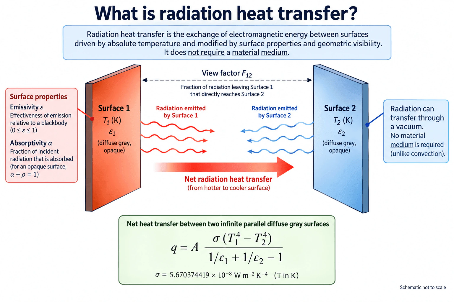
Radiation heat transfer is the exchange of thermal energy by electromagnetic radiation. It does not require a material medium, so it can occur through a vacuum. A surface emits radiation according to its absolute temperature and emissivity. When two surfaces see each other, both emit radiation, but the net heat transfer is from the hotter surface to the cooler surface. The amount exchanged also depends on surface properties and geometric visibility, which is represented by a view factor.
Detailed Explanation
Radiation heat transfer is thermal energy exchange by electromagnetic radiation. Unlike convection, it does not require a fluid or other material medium, so radiation can transfer energy through a vacuum.
A radiating surface is described by its absolute temperature T in kelvin and by radiation properties such as emissivity ε, absorptivity α, and reflectivity ρ. Emissivity describes how effectively a surface emits radiation relative to a blackbody at the same temperature. Absorptivity describes the fraction of incident radiation absorbed, while reflectivity describes the fraction reflected. For an opaque surface, transmission is zero, so α + ρ = 1. These properties should not be treated as interchangeable constants without an appropriate physical assumption. A gray surface model treats the relevant radiative properties as independent of wavelength over the range being modeled, while a diffuse surface model treats them as independent of direction.
Geometry also matters. The view factor F₁₂ is the fraction of radiation leaving Surface 1 that directly reaches Surface 2. For enclosure calculations, view factors should satisfy reciprocity and summation relationships.
Useful Questions to Ask the Interviewer
Are the surfaces being treated as diffuse, gray, and opaque?
Is the geometry a large parallel surface approximation, or should a general view factor be used?
Are the surface temperatures steady and known in kelvin?
How to Explain It in an Interview
Start with two radiating surfaces. Surface 1 is at absolute temperature T₁ with emissivity ε₁, and Surface 2 is at T₂ with emissivity ε₂. Each surface emits electromagnetic radiation toward its surroundings. For a diffuse gray surface, the emitted radiative heat flux is εσT⁴, where σ is the Stefan Boltzmann constant and T must be in kelvin.
The exchange is two way. Surface 1 emits radiation toward Surface 2, and Surface 2 emits radiation toward Surface 1. If T₁ is greater than T₂, the net radiation heat transfer is from Surface 1 to Surface 2 even though both surfaces continue emitting radiation.
Geometric visibility is represented by the view factor F₁₂. It tells us what fraction of radiation leaving Surface 1 directly reaches Surface 2. For two infinite parallel surfaces facing each other, F₁₂ = 1.
For two infinite parallel diffuse gray surfaces with equal area A, the net radiation heat transfer rate shown in the diagram is
q = Aσ(T₁⁴ − T₂⁴) / (1/ε₁ + 1/ε₂ − 1).
The Stefan Boltzmann constant is approximately 5.670374419 × 10⁻⁸ W m⁻² K⁻⁴. The fourth power temperature dependence makes absolute temperature essential.
Useful checks are the limiting cases. If ε₁ = ε₂ = 1, the expression reduces to the blackbody result q = Aσ(T₁⁴ − T₂⁴). If T₁ = T₂, the net exchange is zero. For more general geometries, additional surfaces, or external radiation sources, I would define the physical boundary, determine the applicable view factors and surface properties, and solve the corresponding surface energy balance.
Why Interviewers Ask This
Interviewers want to confirm that you understand the physical basis of thermal radiation, can distinguish it from convection, use absolute temperature correctly, and recognize how emissivity, absorptivity, reflectivity, and geometric view factors affect radiation exchange between surfaces.
Common interview mistakes
Common mistakes include using Celsius instead of kelvin in radiation equations, assuming radiation requires a material medium, treating emissivity and absorptivity as interchangeable constants without stating assumptions, ignoring reflected radiation, forgetting geometric view factors, and applying the infinite parallel surface equation to geometries where its assumptions are not valid.
Interview tip
Explain radiation as a two way electromagnetic exchange first, then state that the net heat transfer is from the hotter surface to the cooler surface. Mention absolute temperature, emissivity, and view factor. If you use the infinite parallel surface equation, state its diffuse gray surface and geometry assumptions before applying it.
Interviewer may ask next
How would you check whether a radiation heat transfer calculation is physically reasonable?
First confirm that every temperature used in a radiation equation is in kelvin. Check that emissivity, absorptivity, reflectivity, and view factors remain within their physical bounds. For an enclosure, check view factor reciprocity and summation. Then test limiting cases. Equal surface temperatures should give zero net exchange, and black surfaces should reduce to the blackbody result. Finally, check the surface energy balances for conservation of energy.
What changes if the two surfaces are not infinite parallel surfaces?
The simple infinite parallel surface equation may no longer apply. Geometric visibility must be represented by the appropriate view factor, and other surfaces or surroundings may participate in the exchange. I would define all relevant radiating surfaces, determine the necessary view factors, apply the surface radiation relations, and solve the resulting surface energy balance while checking reciprocity, summation, and energy conservation.
12. What is emissivity?Radiation Heat TransferEasy
Short Interview Answer (30-60 seconds)
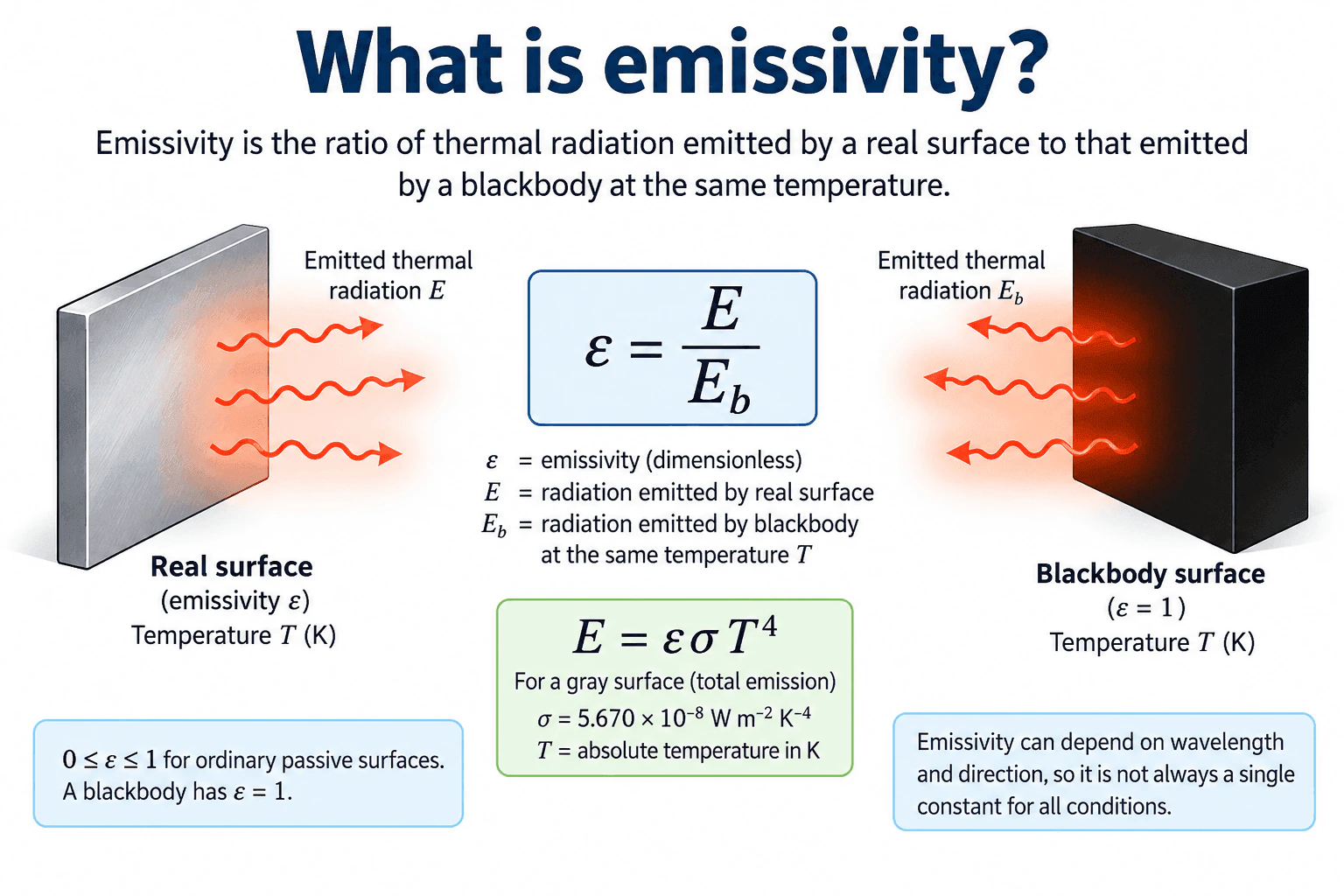
Emissivity, represented by ε, is a dimensionless measure of how effectively a real surface emits thermal radiation compared with a blackbody at the same absolute temperature. It can be written as ε = E / Eb, where E is the emissive power of the real surface and Eb is the blackbody emissive power at the same temperature. For an ordinary passive surface, 0 ≤ ε ≤ 1, and a blackbody has ε = 1. For a gray surface, E = εσT⁴, where T is absolute temperature in kelvin.
Detailed Explanation
Emissivity describes how effectively a real surface emits thermal radiation compared with an ideal blackbody under corresponding conditions. If E is the emissive power of the real surface and Eb is the blackbody emissive power at the same absolute temperature, then ε = E / Eb. Emissivity is dimensionless. A blackbody has ε = 1, while an ordinary passive real surface has 0 ≤ ε ≤ 1.
Useful Questions to Ask the Interviewer
Are we discussing total hemispherical emissivity or a spectral or directional value?
Should I assume the surface behaves as a diffuse gray surface?
Are we considering emission only, or a complete radiation exchange with surrounding surfaces?
How to Explain It in an Interview
Physical Method
Use a blackbody as the reference emitter. At the same absolute temperature T, emissivity tells us what fraction of blackbody emission a real surface produces:
ε = E / Eb
For a gray surface using total emission:
E = εσT⁴
where E is emissive power in W/m², ε is emissivity, σ = 5.670 × 10⁻⁸ W/m²K⁴, and T is absolute temperature in kelvin.
Engineering Reasoning
Emissivity is a surface radiation property. It can depend on wavelength, direction, temperature, and surface condition, so one constant value is appropriate only when the modeling assumptions support it.
Emissivity is not the same property as absorptivity or reflectivity. Absorptivity describes the fraction of incident radiation absorbed, while reflectivity describes the fraction reflected. Kirchhoff's law relates spectral directional emissivity and absorptivity under corresponding equilibrium conditions, but the properties should not be treated as interchangeable constants without checking those conditions.
A view factor is also different. It is a geometric quantity describing the fraction of radiation leaving one surface that reaches another. Emissivity describes the emitting behavior of a surface, while a view factor describes geometric visibility between surfaces.
Assumptions And Checks
Use absolute temperature in radiation equations. Confirm whether the required emissivity is total, spectral, directional, or hemispherical. State a gray surface assumption when using E = εσT⁴ with a single emissivity value. For enclosure radiation exchange, also check the relevant surface temperatures and view factors.
A useful limiting check is ε = 1, which gives blackbody emission. At the same temperature, reducing ε reduces the emitted radiation proportionally under the gray surface model.
Why Interviewers Ask This
Interviewers use this question to check whether a candidate understands how a real surface emits thermal radiation compared with an ideal blackbody and whether the candidate can apply emissivity correctly in radiation calculations.
Common interview mistakes
Common mistakes include using Celsius instead of absolute temperature in T⁴, assuming every surface has one constant emissivity under all conditions, confusing emissivity with absorptivity or reflectivity, treating emissivity as a geometric view factor, and using a tabulated emissivity value without checking the relevant surface condition, wavelength range, direction, or temperature.
Interview tip
Give the definition first, then state ε = E / Eb and the range 0 ≤ ε ≤ 1. Mention that a blackbody has ε = 1 and connect the definition to E = εσT⁴ for a gray surface. To show stronger understanding, add that emissivity can depend on wavelength and direction.
Interviewer may ask next
What assumptions should you check before using a single emissivity value in a radiation calculation?
Check whether the surface can reasonably be treated as gray and diffuse, whether the emissivity value applies to the relevant temperature and surface condition, and whether a total hemispherical value is appropriate for the model. If wavelength or direction matters, use the corresponding spectral or directional emissivity instead of a single constant.
If two gray surfaces have the same absolute temperature but different emissivities, which one emits more thermal radiation?
The surface with the higher emissivity emits more thermal radiation because E = εσT⁴. At the same absolute temperature, emitted radiation is directly proportional to emissivity under the gray surface model. A surface with ε = 1 reaches the blackbody limit.
13. How does surface temperature affect radiative heat transfer?Radiation Heat TransferHard
Short Interview Answer (30-60 seconds)
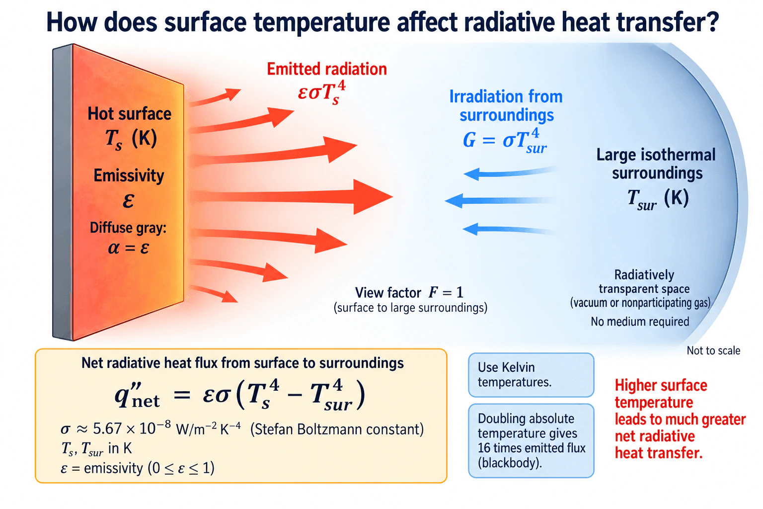
Radiative heat transfer depends strongly on absolute surface temperature because thermal emission follows the Stefan Boltzmann relation, E = εσTs⁴. For the diffuse gray surface and large isothermal surroundings shown, with view factor F = 1 and the surroundings providing G = σTsur⁴, the net radiative heat flux is q''net = εσ(Ts⁴ − Tsur⁴). Temperatures must be in kelvin. Because temperature is raised to the fourth power, increasing surface temperature can greatly increase radiative heat transfer. For example, doubling absolute temperature increases blackbody emission by a factor of 16.
Detailed Explanation
Surface temperature has a strong effect on radiative heat transfer because thermal emission varies with the fourth power of absolute temperature. The physical boundary shown is one hot diffuse gray surface at Ts exchanging radiation with large isothermal surroundings at Tsur through a radiatively transparent region. The surface has emissivity ε and sees the surroundings with view factor F = 1. For this simplified model, the surroundings provide irradiation G = σTsur⁴.
Useful Questions to Ask the Interviewer
May I assume the surface is diffuse, gray, and opaque with constant emissivity?
May I treat the surroundings as large and isothermal with F = 1 and G = σTsur⁴?
Is the region between the surface and surroundings vacuum or a nonparticipating gas?
How to Explain It in an Interview
For a diffuse gray surface, the emitted radiative heat flux is
E = εσTs⁴
where ε is surface emissivity, σ is the Stefan Boltzmann constant, approximately 5.67 × 10⁻⁸ W m⁻² K⁻⁴, and Ts is absolute surface temperature in kelvin.
The large isothermal surroundings provide irradiation
G = σTsur⁴
For the gray surface assumption used in this model, α = ε, so the absorbed irradiation is εG. With F = 1, the net radiative heat flux from the surface to the surroundings becomes
q''net = εσ(Ts⁴ − Tsur⁴)
This shows why temperature is so important. Radiation does not increase linearly with temperature. Because emission varies with T⁴, increasing absolute temperature can produce a much larger change in radiative heat flux. For a blackbody, doubling absolute temperature gives 2⁴ = 16 times the emitted flux.
The sign indicates the direction of net radiation exchange. If Ts > Tsur, the net heat flow is from the surface to the surroundings. If Ts = Tsur, emitted and absorbed radiation balance and the net exchange is zero. If Ts < Tsur, the net direction reverses.
The simplified equation depends on its assumptions. The surface must be represented adequately as diffuse and gray, the geometric view must correspond to F = 1, the surroundings must provide the stated irradiation, and the intervening region must not significantly emit, absorb, or scatter radiation. A participating gas or more complicated geometry requires a more complete radiation model.
I would check that temperatures are in kelvin, 0 ≤ ε ≤ 1, the view factor assumption is appropriate, the sign matches the expected heat flow direction, and q''net approaches zero as Ts approaches Tsur.
Why Interviewers Ask This
Interviewers want to see whether the candidate understands the strong fourth power dependence of thermal radiation on absolute temperature, can distinguish emitted radiation from incoming irradiation, can apply emissivity and absorptivity consistently, and can recognize when the simplified surface to large surroundings model is valid.
Common interview mistakes
Common mistakes include using Celsius instead of kelvin in the fourth power terms, treating radiation as proportional only to temperature difference, confusing irradiation G with absorbed irradiation αG, multiplying G by emissivity before defining the incoming irradiation, assuming α = ε without the appropriate surface assumptions, ignoring view factor effects, and applying the simple large surroundings equation when the intervening gas participates significantly in radiation.
Interview tip
Start with the Stefan Boltzmann fourth power dependence, define the surface and surroundings assumptions, and then write the net exchange equation. Emphasize that temperature strongly controls emission, while emissivity, surroundings temperature, and geometric visibility determine the resulting net radiation exchange.
Interviewer may ask next
What assumptions should you verify before using q''net = εσ(Ts⁴ − Tsur⁴)?
Verify that Ts and Tsur are absolute temperatures, the surface can reasonably be treated as diffuse, gray, and opaque with known emissivity, the surface has the assumed geometric view of the large surroundings, the surroundings provide the stated irradiation, and the intervening region is radiatively transparent or can be treated as a nonparticipating gas. If those assumptions do not hold, use a more complete surface energy balance, view factor network, spectral model, or participating media model as appropriate.
What changes if the surface temperature increases while the surroundings temperature remains constant?
The emitted term εσTs⁴ rises rapidly while the irradiation from the unchanged surroundings remains constant. Therefore the net outward radiative heat flux increases according to εσ(Ts⁴ − Tsur⁴), provided emissivity and the geometric conditions remain unchanged. If emissivity changes materially with temperature or wavelength, that variation must also be included.
14. What is latent heat?Phase Change And Two Phase FlowEasy
Short Interview Answer (30-60 seconds)
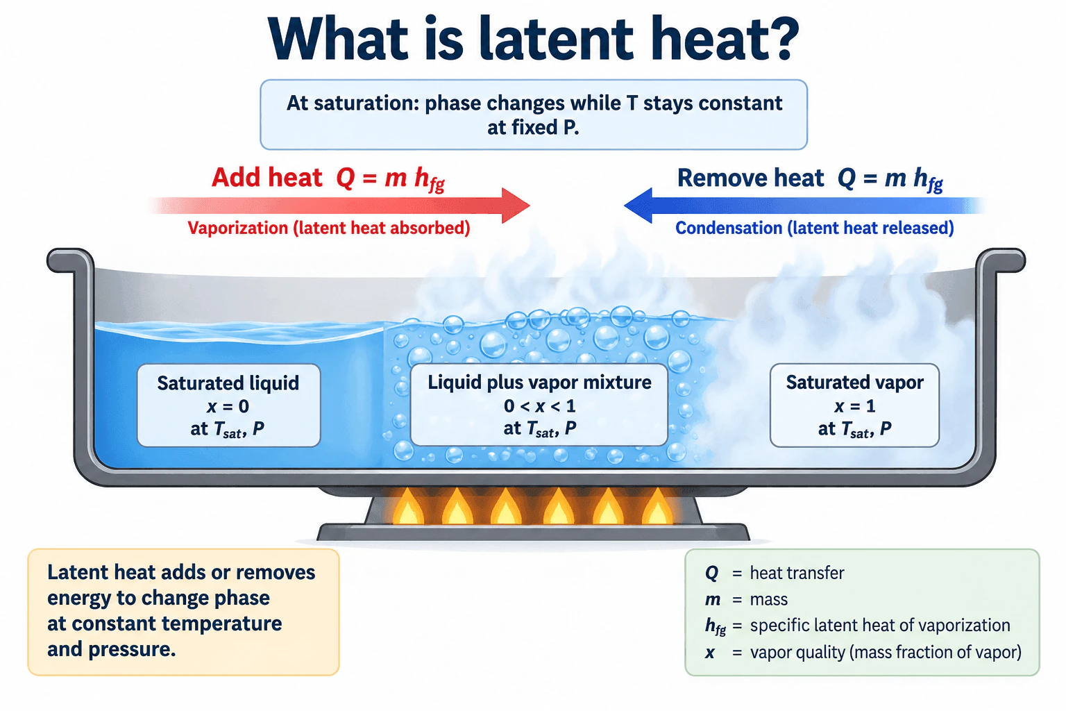
Latent heat is the energy absorbed or released when a substance changes phase without changing temperature under equilibrium conditions at a fixed pressure. During vaporization, heat is absorbed as saturated liquid becomes vapor. During condensation, heat is released as vapor becomes liquid. For a mass m undergoing complete vaporization or condensation, the heat transfer magnitude is Q = m h_fg, where h_fg is the specific latent heat of vaporization in J/kg.
Detailed Explanation
Latent heat is energy associated with changing phase rather than changing temperature. For a pure substance at a specified pressure, liquid and vapor can coexist at the saturation temperature. Adding heat at saturation can convert liquid into vapor while the equilibrium temperature remains at T_sat. Removing heat reverses the process and causes condensation.
Useful Questions to Ask the Interviewer
Should I discuss latent heat for a pure substance at a fixed pressure?
Should I include vapor quality in the explanation?
Do you want only the physical definition, or also the energy balance?
How to Explain It in an Interview
Consider a pure working fluid at fixed pressure P and its corresponding saturation temperature T_sat. The physical boundary contains the fluid undergoing a liquid to vapor or vapor to liquid phase change.
For complete vaporization, the required heat magnitude is Q = m h_fg. Here Q is heat transfer in J, m is the mass undergoing phase change in kg, and h_fg is the specific latent heat of vaporization in J/kg. During condensation, the same relationship gives the magnitude of the heat released.
The key idea is that this energy changes the phase distribution. At saturation, saturated liquid corresponds to x = 0, a liquid plus vapor mixture has 0 < x < 1, and saturated vapor corresponds to x = 1. Vapor quality x is the mass fraction of vapor in the equilibrium liquid plus vapor mixture.
This differs from sensible heating, where added energy primarily changes temperature within a single phase. For an equilibrium phase change at a specified pressure, temperature remains at the saturation temperature while phase conversion proceeds.
The equation Q = m h_fg applies directly when the mass considered undergoes the specified phase change and h_fg is evaluated at the applicable saturation pressure or temperature. Real processes can also include pressure variation, superheating, subcooling, heat losses, and nonequilibrium effects. Those contributions must be treated separately rather than folded into the simple latent heat relation.
A useful physical check is the direction of energy transfer. Vaporization requires heat input, while condensation releases heat. The phase state should move from x = 0 toward x = 1 during vaporization and in the opposite direction during condensation.
Why Interviewers Ask This
Interviewers ask this to check whether a candidate understands the energy associated with a phase change, saturation conditions, vapor quality, and the difference between latent heat and sensible heating. A strong answer should connect the physical process to an energy balance without implying that temperature must rise during an equilibrium phase change.
Common interview mistakes
Common mistakes include saying that latent heat raises the fluid temperature during an equilibrium phase change, confusing latent heat with sensible heat, using h_fg without specifying the saturation state, treating vapor quality as a volume fraction instead of a mass fraction, and applying Q = m h_fg to a process that also includes significant subcooling or superheating without accounting for those additional energy changes.
Interview tip
Start with the physical definition, then connect it to saturation and the equation Q = m h_fg. Mention that vaporization absorbs heat, condensation releases heat, and vapor quality describes the liquid and vapor distribution inside the saturation region. This gives a complete answer without introducing unrelated two phase flow details.
Interviewer may ask next
How would you verify that Q = m h_fg is appropriate for a calculation?
Confirm that the fluid is undergoing the intended phase change near equilibrium, identify the pressure or saturation temperature, obtain h_fg for that state, and verify that the mass in the equation is the mass actually changing phase. Also check whether sensible heating, superheating, subcooling, pressure changes, or heat losses are large enough to require additional energy terms.
What changes if the fluid enters as a subcooled liquid and leaves as superheated vapor?
The total heat transfer is no longer only latent heat. Energy is first required to heat the subcooled liquid to saturation, then latent heat is required for vaporization, and additional sensible heat is required to raise the saturated vapor into the superheated region. The energy balance must therefore include each applicable enthalpy change rather than using only m h_fg.
15. What is the difference between sensible heat and latent heat?Phase Change And Two Phase FlowEasy
Short Interview Answer (30-60 seconds)
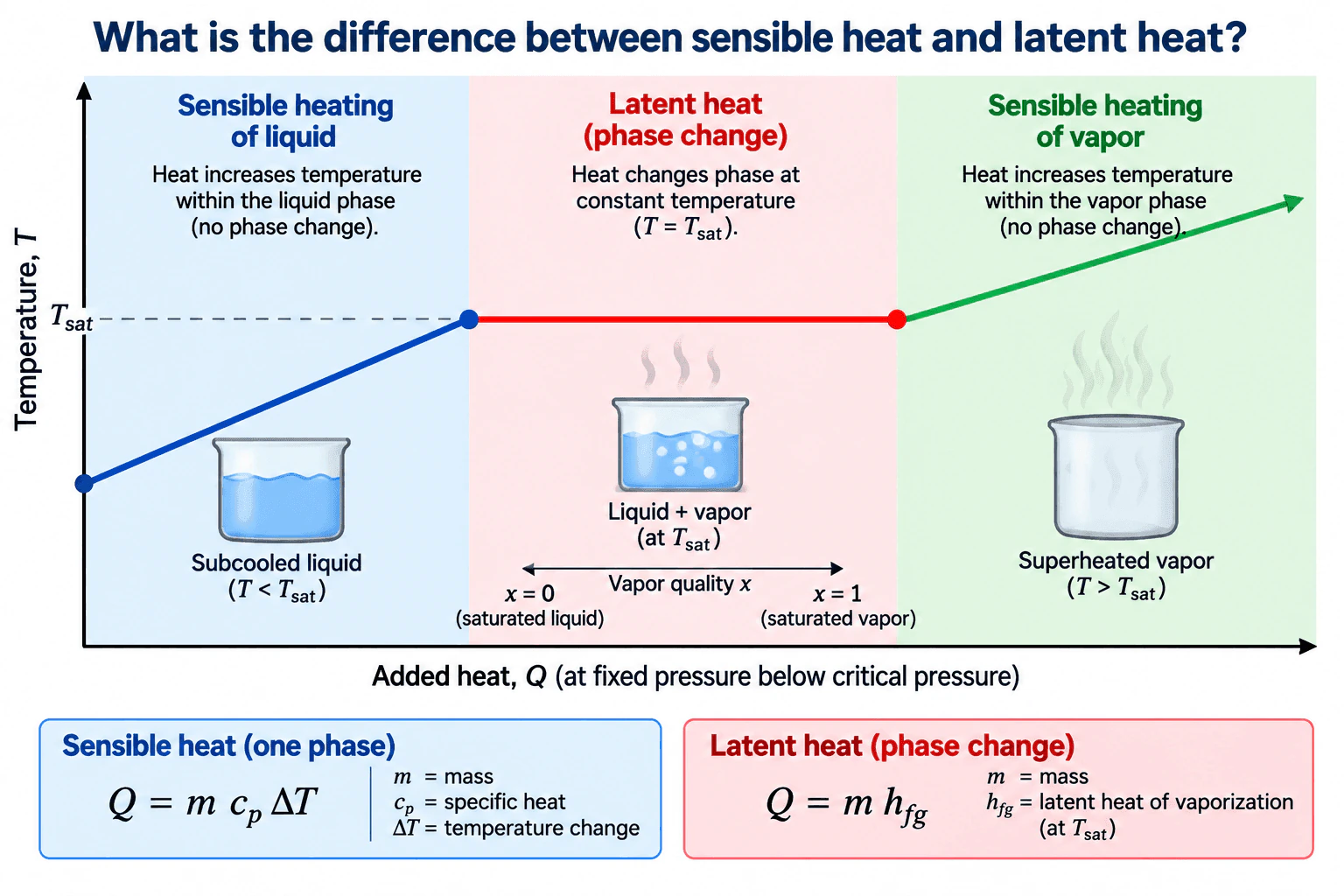
Sensible heat changes the temperature of a material without changing its phase. For a single phase with approximately constant specific heat, Q = m c_p ΔT. Latent heat changes the phase while the temperature remains at approximately the saturation temperature for an equilibrium process at fixed pressure. For complete vaporization from saturated liquid to saturated vapor, Q = m h_fg. During vaporization, vapor quality increases from x = 0 at saturated liquid to x = 1 at saturated vapor.
Detailed Explanation
Sensible heat and latent heat describe two different effects of thermal energy. Sensible heat changes temperature while the material remains in one phase. Latent heat changes phase while the temperature remains approximately constant during an equilibrium phase change at fixed pressure.
Useful Questions to Ask the Interviewer
Should I explain the difference using vaporization at fixed pressure?
Should I assume a pure working fluid below its critical pressure?
Should I assume specific heat is approximately constant over each sensible heating range?
How to Explain It in an Interview
Consider a pure working fluid heated at fixed pressure below its critical pressure.
Start with a subcooled liquid, where T < T_sat. Added heat raises the liquid temperature while it remains liquid. This is sensible heating. If specific heat is approximately constant,
Q = m c_p ΔT
where Q is heat in joules, m is mass in kilograms, c_p is specific heat in joules per kilogram kelvin, and ΔT is the temperature change in kelvin.
When the liquid reaches the saturation temperature T_sat at that pressure, further heat can convert liquid to vapor. During an equilibrium phase change at fixed pressure, the temperature remains approximately T_sat while the phase distribution changes. This is latent heating. For complete vaporization from saturated liquid to saturated vapor,
Q = m h_fg
where h_fg is the latent heat of vaporization in joules per kilogram.
Inside the saturated liquid and vapor region, vapor quality x is the vapor mass fraction. At x = 0 the state is saturated liquid. At x = 1 the state is saturated vapor. Adding latent heat increases x from 0 toward 1 while the equilibrium temperature remains approximately constant.
After x reaches 1, no liquid remains. Further heat raises the vapor temperature above T_sat. The vapor becomes superheated, so the additional energy is again sensible heat.
The reverse process follows the same distinction. Sensible heat removal lowers temperature within one phase, while condensation rejects latent heat as vapor changes to liquid at saturation conditions.
The constant temperature statement assumes an equilibrium phase change of a pure substance at fixed pressure. If pressure changes, the corresponding saturation temperature also changes.
Why Interviewers Ask This
Interviewers want to see whether the candidate can distinguish temperature change within one phase from energy absorbed or released during a phase change, and whether the candidate understands saturation temperature, vapor quality, subcooling, and superheat.
Common interview mistakes
Common mistakes include treating latent heat as a temperature rise, using Q = m c_p ΔT across the phase change region, assuming saturation temperature is independent of pressure, confusing vapor quality with volume fraction, and using Q = m h_fg when the material is not undergoing the corresponding phase change.
Interview tip
Explain one continuous heating path that matches the diagram: subcooled liquid first undergoes sensible heating, the saturated liquid and vapor mixture then absorbs latent heat while vapor quality increases from x = 0 to x = 1, and the resulting vapor undergoes sensible heating again as it becomes superheated.
Interviewer may ask next
When is it valid to say that temperature remains constant during latent heating?
It is valid for an equilibrium phase change of a pure substance at fixed pressure. Under those conditions the phase change occurs at the saturation temperature associated with that pressure. If pressure changes, the saturation temperature changes as well.
What happens after all saturated liquid has become saturated vapor?
At x = 1 the vaporization process is complete and no liquid remains. Further heat raises the vapor temperature above the saturation temperature, producing superheated vapor. That additional energy is sensible heat rather than latent heat.
16. What is critical heat flux?Phase Change And Two Phase FlowMedium
Short Interview Answer (30-60 seconds)
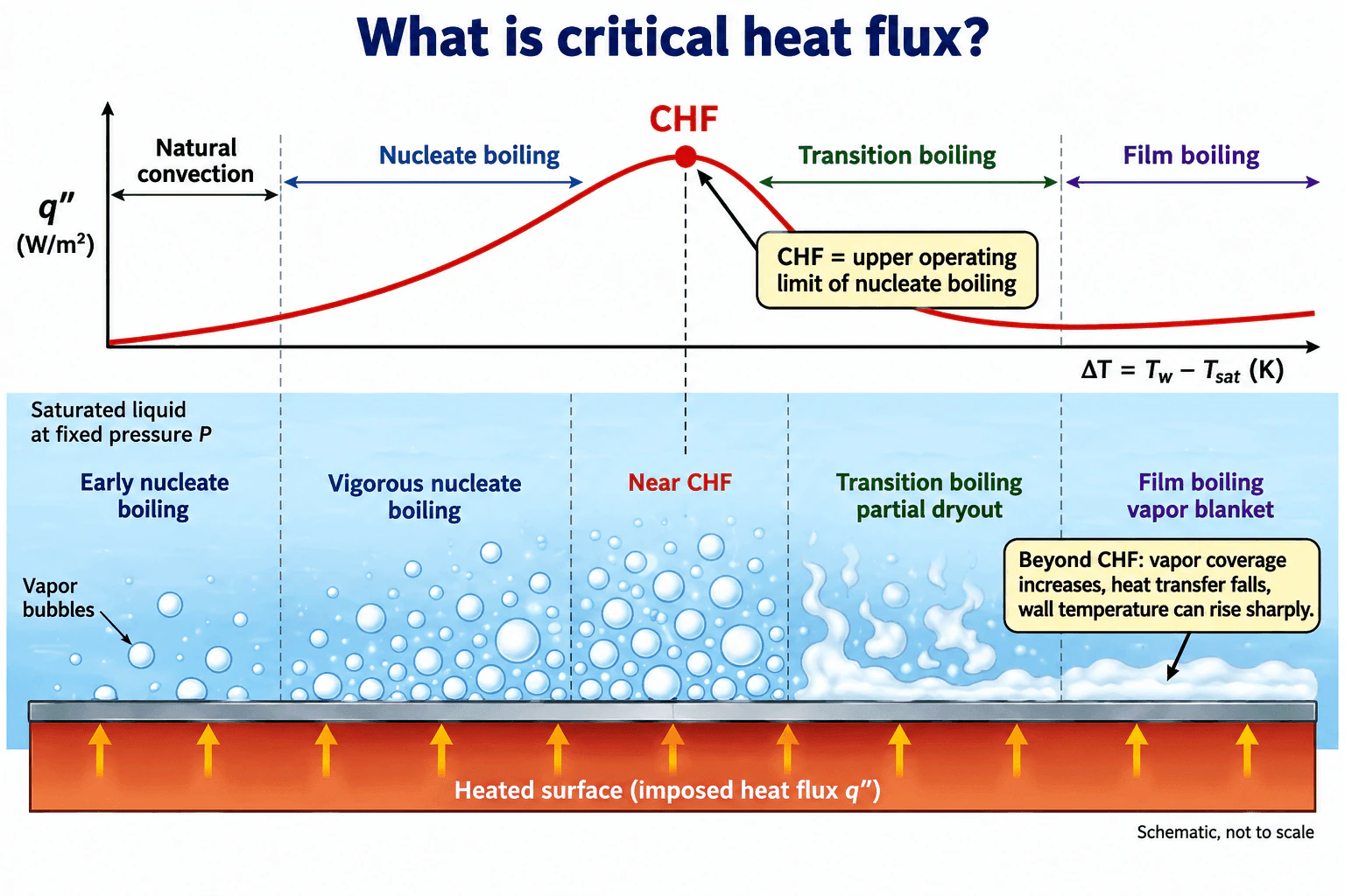
Critical heat flux, or CHF, is the maximum heat flux reached at the upper limit of nucleate boiling. As heat input increases, vapor generation becomes intense and liquid access to the heated surface becomes restricted. At CHF, the surface begins to lose effective wetting. Beyond this point, vapor coverage increases, heat transfer becomes less effective, and the wall temperature can rise sharply as boiling moves toward transition boiling and film boiling.
Detailed Explanation
Critical heat flux is the peak heat flux that marks the upper operating limit of nucleate boiling. In the approved diagram, the physical boundary is an upward facing horizontal heated surface beneath a saturated liquid at fixed pressure. The working fluid is not specified, so no fluid specific CHF value should be assumed. The relevant temperature driving quantity is wall superheat, ΔT = T_w − T_sat, where T_w is wall temperature and T_sat is saturation temperature at the operating pressure.
At low wall superheat, heat transfer is dominated by natural convection. As wall superheat increases, nucleate boiling begins. Vapor bubbles form at the heated surface, grow, and depart while liquid continues to rewet the surface. Increasing bubble activity allows heat flux to rise strongly with only a moderate increase in wall temperature.
CHF occurs at the peak of the nucleate boiling region. Near this point, vapor generation is intense enough that liquid access to parts of the surface becomes restricted. This is the onset of a boiling crisis or dryout condition for the local surface.
Beyond CHF, vapor increasingly covers the surface. In the transition boiling region, partial dryout and unstable liquid contact reduce heat transfer effectiveness. At still higher wall temperature, a more continuous vapor blanket forms and film boiling develops. Because vapor has much poorer heat transfer performance than direct liquid contact in nucleate boiling, the surface temperature can become much higher.
The diagram uses heat flux q'' on the vertical axis and ΔT = T_w − T_sat on the horizontal axis. It is schematic and not to scale. It represents the operating range from natural convection through nucleate boiling, CHF, transition boiling, and film boiling. A single bulk vapor quality is not assigned because this is a local pool boiling picture rather than a defined flowing two phase mixture.
Useful Questions to Ask the Interviewer
Should I explain CHF for saturated pool boiling at fixed pressure, as shown here, or for forced flow boiling?
Is the boundary condition imposed heat flux or imposed wall temperature?
Do you want only the physical definition, or also discussion of CHF correlations and engineering margin?
How to Explain It in an Interview
Physical Method
I would first define the operating condition. The diagram represents saturated liquid above an upward facing horizontal heated surface at fixed pressure. The fluid is unspecified, so I would not assume a numerical CHF value.
I would then follow the boiling curve using heat flux q'' versus wall superheat ΔT = T_w − T_sat. Natural convection appears first. Nucleate boiling follows as bubbles form and depart while liquid repeatedly rewets the surface. Heat transfer is very effective in this regime.
CHF is the maximum heat flux at the upper limit of nucleate boiling. Near CHF, vapor generation becomes so intense that vapor begins to restrict liquid access to the wall.
Engineering Reasoning
Beyond CHF, parts of the surface lose effective liquid contact. This produces transition boiling with partial dryout and lower heat transfer effectiveness. At sufficiently high wall temperature, a stable vapor blanket can form and film boiling develops.
For an imposed heat flux system, crossing CHF is especially important because the required heat input remains while the boiling heat transfer effectiveness falls. The wall temperature can therefore rise sharply. Under imposed wall temperature, the boiling curve can be traversed differently because heat flux is allowed to respond to the selected wall temperature.
Assumptions And Checks
The drawing is schematic and not to scale. Pressure is fixed and the liquid is initially saturated. No numerical CHF is calculated because fluid properties, pressure, surface condition, geometry, orientation, and flow conditions determine the actual value. Any CHF correlation must be used only within its validated regime and geometry.
Why Interviewers Ask This
This checks whether the candidate understands the physical limit of nucleate boiling, recognizes the loss of effective liquid contact with the heated surface near that limit, and can explain why exceeding critical heat flux can cause a large increase in wall temperature.
Common interview mistakes
Common mistakes are defining CHF as the start of boiling, confusing CHF with the minimum heat flux associated with stable film boiling, assuming one universal CHF value, ignoring pressure and surface conditions, or applying a CHF correlation outside the geometry, orientation, pressure, or flow regime for which it was developed.
Interview tip
Anchor the explanation to the boiling curve. State that CHF is the peak heat flux at the upper limit of nucleate boiling, then explain the physical reason: intense vapor generation restricts liquid contact with the heated surface, so dryout can begin and wall temperature can rise sharply.
Interviewer may ask next
What conditions would you verify before using a critical heat flux correlation?
I would verify the working fluid, absolute pressure, saturation or subcooling condition, geometry, characteristic dimensions, surface orientation, flow condition, mass flux when applicable, surface condition, heating method, and whether the correlation was developed for pool boiling or flow boiling. I would also check the stated validity range and compare the result with independent published evidence before treating it as an engineering operating limit.
How does the engineering concern change if heat flux is imposed instead of wall temperature?
With imposed heat flux, exceeding CHF can cause a severe wall temperature rise because the required heat input remains while vapor coverage reduces heat transfer effectiveness. With imposed wall temperature, heat flux can decrease as the surface moves into transition boiling, so the path through the boiling curve is different. The thermal boundary condition therefore matters when interpreting CHF behavior.
17. What factors determine the boiling heat transfer coefficient?Phase Change And Two Phase FlowHard
Short Interview Answer (30-60 seconds)
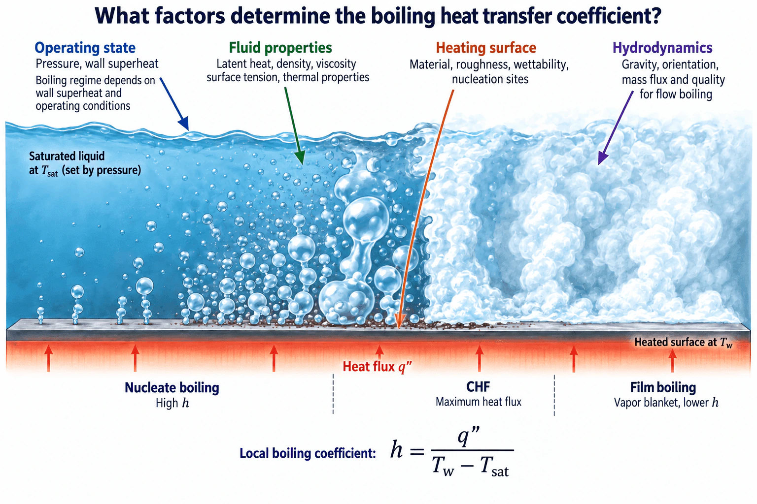
The boiling heat transfer coefficient depends mainly on pressure and wall superheat, fluid properties, heating surface condition, hydrodynamics, and the active boiling regime. For saturated boiling, the local coefficient can be written as h = q″ / (T_w − T_sat). Nucleate boiling usually gives high h because bubbles form and depart while liquid continues to wet the surface. Critical heat flux marks the maximum heat flux on the nucleate boiling branch before major deterioration of wall wetting. If a stable vapor blanket develops, film boiling occurs and h becomes much lower. For flow boiling, mass flux and vapor quality are also important.
Detailed Explanation
For saturated boiling of a specified working fluid, the local heat transfer coefficient can be expressed as h = q″ / (T_w − T_sat), where h is in W/m²K, q″ is wall heat flux in W/m², T_w is wall temperature, and T_sat is the saturation temperature at the local pressure. The coefficient is controlled by the physical boiling mechanism at the heated surface rather than by one property alone.
Useful Questions to Ask the Interviewer
Are we considering saturated pool boiling or flow boiling?
What working fluid, pressure, surface condition, and orientation should I assume?
Is the operating point expected to remain in nucleate boiling, or should I evaluate critical heat flux and film boiling?
How to Explain It in an Interview
Start with the operating state. For a given pure fluid, pressure sets the saturation temperature. Wall superheat, T_w − T_sat, strongly influences which boiling regime is active. The working fluid, pressure, saturation state, and expected operating range should therefore be defined before selecting a correlation. The diagram assumes saturated liquid. If the bulk liquid is below T_sat, subcooled boiling behavior must be treated separately.
Next consider fluid properties. Latent heat, liquid and vapor density, viscosity, surface tension, specific heat, and thermal transport properties influence bubble formation, growth, departure, and liquid replenishment at the wall. These properties should be evaluated consistently with the thermodynamic state required by the chosen correlation.
The heating surface also changes h. Material, roughness, wettability, cleanliness, and active nucleation sites affect how readily bubbles form and detach. Two surfaces exposed to the same fluid, pressure, and wall superheat can therefore produce different boiling coefficients.
Hydrodynamics control vapor removal and liquid supply to the wall. Gravity and orientation matter in pool boiling. In flow boiling, mass flux and vapor quality also affect phase distribution and the local heat transfer mechanism.
The boiling regime is especially important. Nucleate boiling generally gives high h because repeated bubble formation and departure maintain effective liquid contact with the surface. Critical heat flux marks the maximum heat flux reached before major deterioration of wall wetting. Beyond this point, transition boiling can occur before a stable vapor blanket develops. In film boiling, the vapor layer thermally separates much of the liquid from the surface, so h is much lower and wall temperature can rise sharply. In flow boiling, dryout is another important loss of liquid contact that must be checked with a method appropriate to that regime.
I would select a correlation only after defining the fluid, pressure, saturation state, surface condition, orientation, flow condition, and regime. I would then verify that the operating point lies within the correlation's stated applicability range and check the relevant critical heat flux or dryout limit independently.
Why Interviewers Ask This
This question tests whether the candidate understands that the boiling heat transfer coefficient is not a fixed fluid property. It depends on the operating state, fluid properties, heating surface characteristics, hydrodynamics, and boiling regime. It also tests whether the candidate recognizes critical heat flux, deterioration of wall wetting, and vapor blanketing as important operating limits.
Common interview mistakes
Common mistakes include treating h as a constant fluid property, ignoring the effect of pressure on T_sat, neglecting surface roughness or wettability, using a nucleate boiling correlation outside the nucleate boiling regime, and applying pool boiling assumptions to flow boiling without accounting for mass flux and vapor quality. Another mistake is assuming that increasing wall superheat always improves cooling even after critical heat flux, dryout, or vapor blanketing begins.
Interview tip
Organize the answer around five ideas: operating state, fluid properties, heating surface, hydrodynamics, and boiling regime. State h = q″ / (T_w − T_sat), then explain that the physical mechanism controlling q″ changes with the regime. Mention critical heat flux and film boiling explicitly because they show that you understand the operating limit rather than treating boiling as one continuous mechanism.
Interviewer may ask next
How would you validate a predicted boiling heat transfer coefficient?
I would confirm that the working fluid, pressure, saturation state, surface condition, orientation, mass flux, and vapor quality match the assumptions of the selected correlation. I would verify units and thermophysical properties, compare the result with an independent correlation or suitable experimental data from the same boiling regime, and confirm that the operating point remains within the stated applicability range. I would also check the relevant margin to critical heat flux or dryout instead of assuming that a calculated h alone proves acceptable operation.
What changes if the problem is flow boiling instead of pool boiling?
Flow boiling adds forced flow and changing phase distribution. Mass flux and vapor quality become important in addition to pressure, wall superheat, fluid properties, surface condition, gravity, and orientation. The local mechanism can change as vapor quality changes along the flow path, so a pool boiling correlation alone may not represent the full process. I would use a flow boiling method appropriate to the local regime and check critical heat flux or dryout where applicable.
18. What is the continuity equation in CFD and what does it enforce?Numerical Modeling And CfdEasy
Short Interview Answer (30-60 seconds)
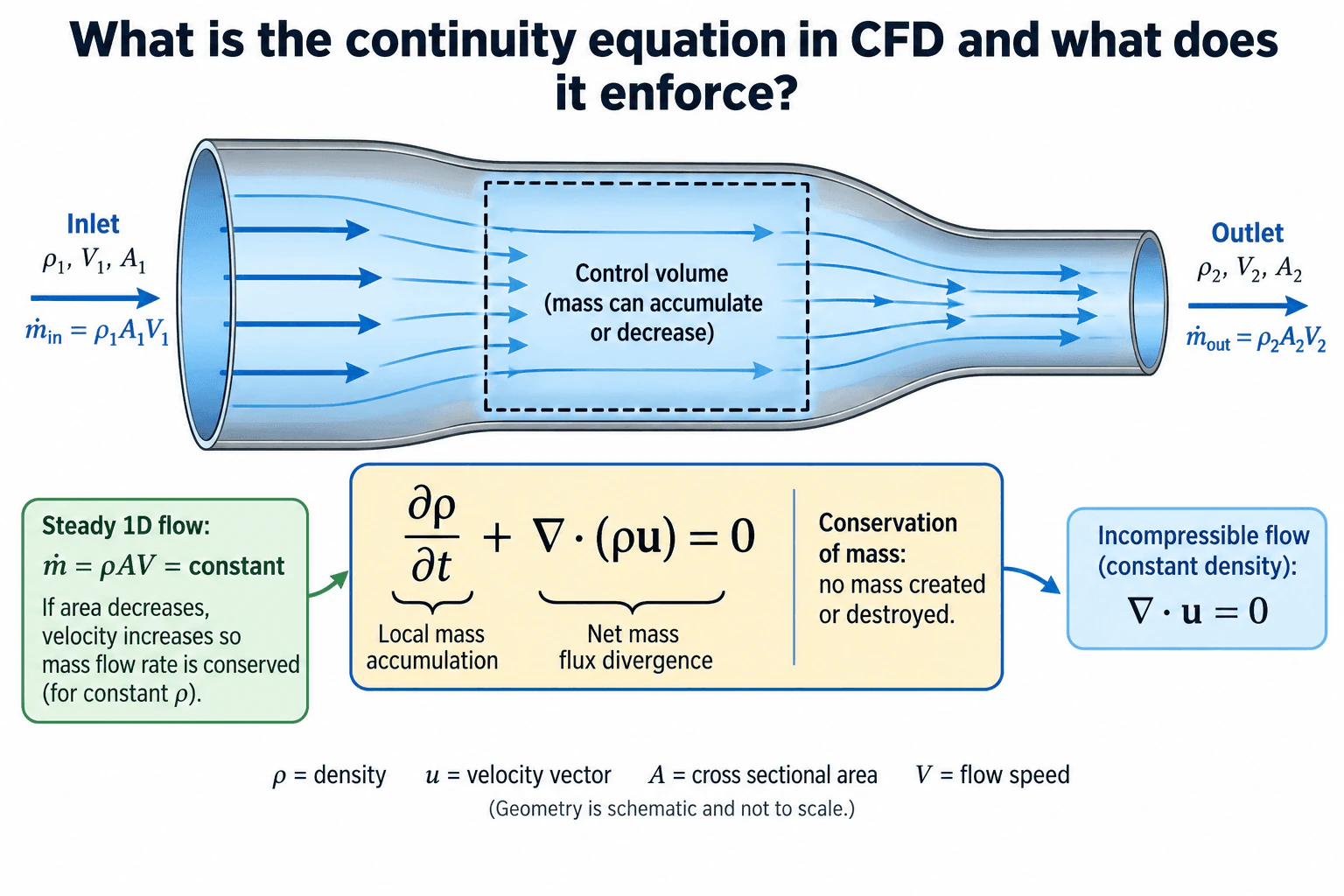
The continuity equation in CFD expresses conservation of mass. Its general differential form is ∂ρ/∂t + ∇ · (ρu) = 0, where ρ is density and u is the velocity vector. The first term represents local mass accumulation, while the second represents net mass flux divergence. Together they require that mass is neither created nor destroyed. For steady one dimensional flow, ṁ = ρAV = constant. For constant density incompressible flow, the equation reduces to ∇ · u = 0.
Detailed Explanation
The continuity equation is the mathematical statement of conservation of mass in CFD. For a fluid with density ρ and velocity vector u, the general differential form is:
∂ρ/∂t + ∇ · (ρu) = 0
The term ∂ρ/∂t represents local mass accumulation or decrease within a small control volume. The term ∇ · (ρu) represents net mass flux divergence. Together, the terms require any change in mass stored inside the control volume to be balanced by mass entering or leaving it.
Useful Questions to Ask the Interviewer
Should I explain the general variable density form or assume constant density flow?
Would you like the steady one dimensional form as well as the differential form?
Should I also explain how mass conservation is checked in a CFD solution?
How to Explain It in an Interview
Start with the physical principle: mass cannot be created or destroyed within the fluid domain.
For the general CFD case:
∂ρ/∂t + ∇ · (ρu) = 0
Here, ρ is density in kg/m³ and u is the velocity vector in m/s. The first term represents local mass accumulation or decrease. The second term represents net mass flux divergence through the control volume boundary.
For steady one dimensional flow through a duct:
ṁ = ρAV = constant
where ṁ is mass flow rate in kg/s, A is cross sectional area in m², and V is flow speed in m/s. This means the inlet and outlet mass flow rates must balance. For two sections:
ρ₁A₁V₁ = ρ₂A₂V₂
If density is constant, a decrease in flow area requires an increase in velocity so the same mass flow rate is maintained.
For constant density incompressible flow, continuity reduces to:
∇ · u = 0
This does not mean velocity is constant. It means the velocity field has zero divergence, which is consistent with no net volumetric expansion or compression of a constant density fluid element.
In a CFD solution, continuity should also be checked numerically. For a steady control volume with no mass sources, the total inlet mass flow should closely balance the total outlet mass flow within the required numerical accuracy. A significant imbalance can indicate inadequate convergence, unsuitable boundary conditions, or insufficient numerical resolution.
The key conclusion is that continuity enforces conservation of mass throughout the CFD domain.
Why Interviewers Ask This
Interviewers want to confirm that the candidate understands conservation of mass as a fundamental CFD requirement and can connect the differential continuity equation to mass flow through a control volume. They also want to see whether the candidate recognizes the steady flow and incompressible flow forms without applying those assumptions incorrectly.
Common interview mistakes
Common mistakes include saying continuity means velocity is constant, using ∇ · u = 0 without stating the constant density assumption, confusing mass flow rate with volumetric flow rate, ignoring density changes when they matter, and checking only residuals without also checking the inlet and outlet mass balance.
Interview tip
Lead with conservation of mass, write the general equation, and explain the two terms physically. Then show the steady one dimensional relation ṁ = ρAV and the constant density form ∇ · u = 0. State the assumption before using each simplified form.
Interviewer may ask next
How would you verify that continuity is being satisfied in a steady CFD solution?
Integrate the mass flow across all inlet and outlet boundaries and compare the totals. With no internal mass sources, the total mass entering should closely equal the total mass leaving within the required numerical tolerance. I would also review continuity residual behavior and confirm that the mass imbalance decreases with further convergence or numerical refinement rather than relying on residuals alone.
How does the continuity equation change when density is not constant?
The constant density simplification ∇ · u = 0 is no longer generally sufficient. The full equation ∂ρ/∂t + ∇ · (ρu) = 0 must be retained so density changes, local accumulation, and transported mass are represented. In steady variable density flow, the time term becomes zero, but density remains inside the mass flux term, so changes in density can be balanced by changes in velocity and flow area.
19. What is a mesh independence study in CFD?Numerical Modeling And CfdMedium
Short Interview Answer (30-60 seconds)
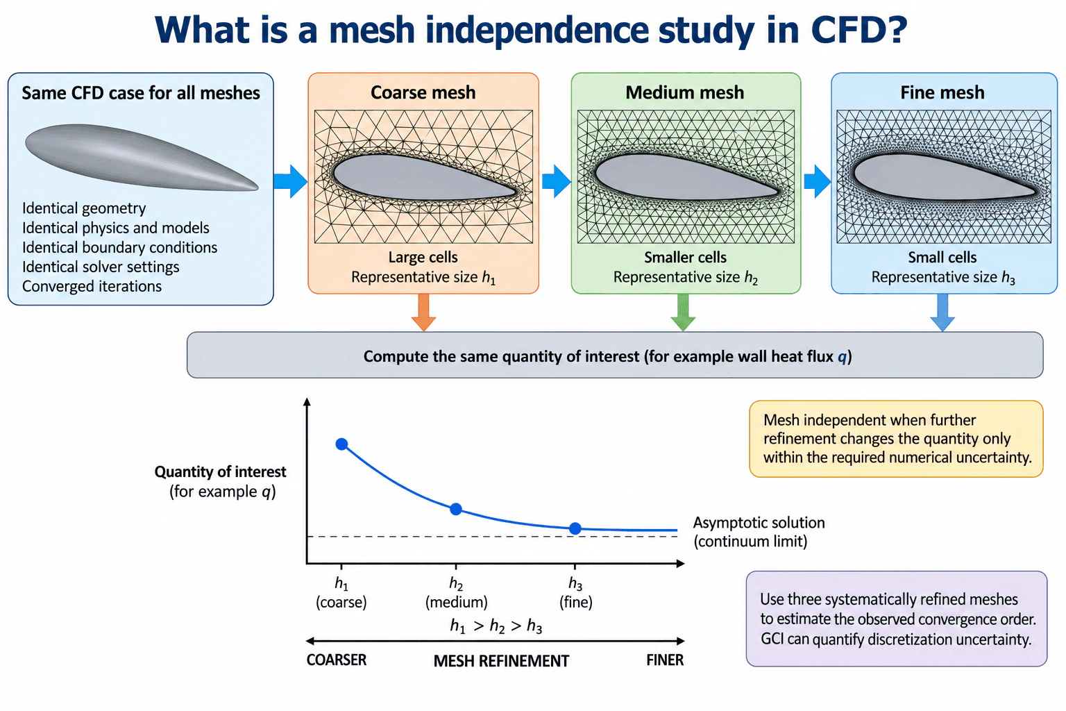
A mesh independence study checks whether a CFD result changes materially as the computational mesh is refined. I would keep the geometry, physics models, properties, boundary conditions, solver settings, and convergence criteria consistent, then solve the same case on systematically refined coarse, medium, and fine meshes. I would compare the same quantity of interest, such as wall heat flux. As the representative mesh size decreases, the result should approach a limiting value. If further refinement changes the quantity only within the required numerical uncertainty, the result is practically mesh independent. Three systematically refined meshes can also support estimation of the observed convergence order and Grid Convergence Index.
Detailed Explanation
A mesh independence study is a numerical verification exercise used to determine whether an engineering result is sufficiently insensitive to spatial mesh resolution. The objective is not simply to use the finest possible mesh. The objective is to demonstrate that further mesh refinement produces only an acceptably small change in the quantity of interest.
Useful Questions to Ask the Interviewer
What quantity of interest must be checked, such as wall heat flux, pressure drop, maximum temperature, or force?
What accuracy or numerical uncertainty is acceptable for that quantity?
Is the problem steady, or must time step convergence also be demonstrated?
How to Explain It in an Interview
First, I would define the modeling objective and required accuracy. I would state the geometry assumptions, physical domain, heat sources when applicable, material or fluid properties, operating conditions, and boundary conditions. These physical inputs should remain consistent during the mesh study.
Next, I would create systematically refined meshes. For example, I could use coarse, medium, and fine meshes with representative cell sizes h₁, h₂, and h₃, where h₁ > h₂ > h₃. Refinement should resolve important thermal and flow gradients, especially near walls and other regions where the solution changes rapidly.
I would solve the same physical case on every mesh using consistent physics models, boundary conditions, solver settings, and convergence criteria. Each solution must also be sufficiently converged with respect to iterations. I would check residual behavior, conservation, and near wall treatment when those checks are applicable.
I would then compare the same engineering quantity on every mesh. In a thermal CFD example, this could be wall heat flux q. As the mesh is refined, the computed quantity should approach an asymptotic continuum value and become progressively less sensitive to mesh spacing.
The practical criterion is whether the change caused by further refinement is smaller than the required numerical uncertainty. With three systematically refined meshes, I can also estimate the observed convergence order and use a Grid Convergence Index approach to quantify spatial discretization uncertainty.
This study provides numerical verification. It does not prove that the physical model represents reality. Validation is a separate activity that compares CFD predictions with independent experimental measurements or other trusted physical evidence. The final mesh should therefore provide adequate numerical accuracy at a reasonable computational cost, with the remaining discretization uncertainty reported.
Why Interviewers Ask This
Interviewers want to know whether you can separate spatial discretization effects from the physical result and provide numerical evidence that the reported CFD quantity is not materially controlled by mesh resolution. They are also checking whether you keep the physical model, boundary conditions, and solver setup consistent while refining the mesh, evaluate a meaningful quantity of interest, quantify remaining discretization uncertainty, and distinguish numerical verification from experimental validation.
Common interview mistakes
Common mistakes include changing the physical model or boundary conditions between meshes, comparing different quantities on different meshes, relying only on residual convergence, refining only the total cell count without resolving important gradients, using meshes that are not systematically related, declaring mesh independence because contour plots look similar, and confusing numerical verification with experimental validation. Another mistake is selecting the finest available mesh without checking whether the additional computational cost produces a meaningful reduction in discretization uncertainty.
Interview tip
State the core logic clearly: keep the physical problem the same, systematically refine the mesh, compare the same quantity of interest, and demonstrate that the result approaches a limiting value within the required numerical uncertainty. Mentioning observed convergence order and Grid Convergence Index demonstrates stronger numerical verification knowledge, while separating verification from validation shows sound engineering judgment.
Interviewer may ask next
How would you validate a mesh independent CFD result?
Mesh independence addresses spatial discretization error, not whether the physical model represents reality. After numerical verification, I would compare important CFD outputs with independent experimental measurements, trusted benchmark data, or another suitable physical reference under matching operating and boundary conditions. I would account for uncertainty in both the simulation and the reference data and investigate systematic differences without tuning inputs unless there is a physical justification.
What changes if the CFD problem is transient?
For a transient problem, spatial mesh convergence alone is not sufficient because time discretization can also affect the result. I would check spatial resolution and then repeat the analysis with progressively smaller time steps while keeping the physical case consistent. I would compare relevant transient quantities such as peak temperature, oscillation amplitude, frequency, or time averaged heat transfer and confirm that both mesh sensitivity and time step sensitivity are within the required numerical uncertainty.
20. What is thermal contact resistance and why does it matter in thermal design?Thermal Materials And InterfacesEasy
Short Interview Answer (30-60 seconds)
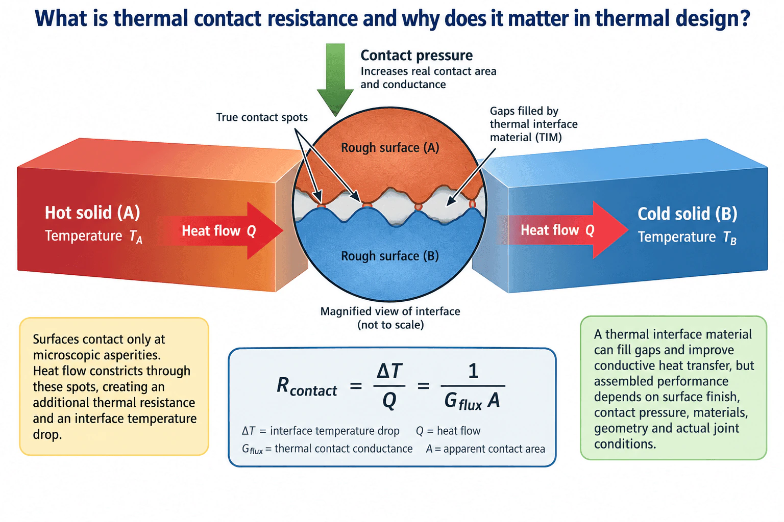
Thermal contact resistance is the resistance to heat flow where two solid surfaces meet. Real surfaces are rough, so they touch only at microscopic contact spots while gaps remain between them. Heat constricts through those small contact regions, creating an interface temperature drop. It can be expressed as R_contact = ΔT / Q. Increasing contact pressure can increase real contact area, while a suitable thermal interface material can fill gaps and improve heat transfer. The actual resistance still depends on surface finish, materials, geometry, pressure, and the assembled joint condition.
Detailed Explanation
Thermal contact resistance occurs at the boundary between two solids because real surfaces are not perfectly smooth. In the diagram, heat flows as Q from hot solid A at temperature T_A toward cold solid B at temperature T_B. Although the solids appear to touch over the full apparent area, their rough surfaces actually meet only at microscopic contact spots. The remaining gaps contain gas or thermal interface material. Heat therefore constricts through the limited real contact area, which creates an additional temperature drop across the interface.
For the defined interface,
R_contact = ΔT / Q
where R_contact is thermal contact resistance in K/W, ΔT is the interface temperature drop in K, and Q is heat flow in W.
Using the contact conductance notation shown in the diagram,
R_contact = 1 / (G_flux A)
where G_flux is thermal contact conductance per unit apparent area in W/(m²·K), and A is apparent contact area in m².
Useful Questions to Ask the Interviewer
What materials and surface finishes form the interface?
What contact pressure or mechanical loading is maintained during operation?
Is a thermal interface material used, and what temperature range and environmental exposure must the joint tolerate?
How to Explain It in an Interview
Physical Method
I would first define the heat path from the hot solid, through the interface, and into the cold solid. I would identify the apparent contact area, surface condition, contact pressure, operating temperature range, and whether a thermal interface material fills the microscopic gaps.
The central idea is that apparent contact area is not the same as real contact area. Rough surfaces touch mainly at asperities. Heat must constrict through those true contact spots, so the interface produces an additional temperature drop and thermal resistance.
Increasing contact pressure generally increases the real contact area and can increase thermal contact conductance. A suitable thermal interface material can fill gaps that would otherwise contain poorly conducting gas and can improve conductive heat transfer. However, assembled performance cannot be predicted from thermal interface material conductivity alone. Surface finish, pressure, materials, geometry, interface thickness, and the actual joint condition all matter.
Assumptions And Checks
I would state whether the interface is treated as steady state and whether the same heat flow Q crosses the interface. I would keep units consistent and distinguish the interface temperature drop from temperature differences elsewhere in the heat path.
For validation, I would compare predicted or measured resistance with independent interface qualification data under representative pressure and temperature conditions. If a thermal interface material is used, I would also verify its assembled thickness and condition after mechanical and environmental exposure.
Engineering Reasoning
Thermal contact resistance matters because it can consume a significant part of the total thermal resistance budget. Even highly conductive solids can have poor assembled thermal performance when the interface has limited real contact area. The resulting additional temperature rise can reduce thermal margin.
The design objective is therefore to create and qualify an interface that maintains adequate thermal conductance under the expected mechanical, thermal, and environmental conditions.
Why Interviewers Ask This
Interviewers want to see whether the candidate understands that two apparently touching solids do not make perfect thermal contact. They are evaluating judgment about real contact area, surface roughness, contact pressure, thermal interface material behavior, interface temperature drop, and why assembled interface performance must be evaluated rather than inferred from material conductivity alone.
Common interview mistakes
Common mistakes include assuming two solids have perfect thermal contact, treating the full apparent area as the true conducting area, using catalog thermal interface material conductivity as though it were the complete joint performance, ignoring contact pressure and surface finish, and measuring temperatures far from the interface while calling that difference the contact temperature drop.
Interview tip
Start with the physical picture shown in the diagram: rough surfaces touch only at microscopic spots, so heat constricts through limited real contact area and creates an interface temperature drop. Then state R_contact = ΔT / Q and explain how contact pressure and a suitable thermal interface material can reduce resistance while emphasizing that actual assembled performance must be qualified under representative joint conditions.
Interviewer may ask next
How would you validate thermal contact resistance for a real assembly?
I would define the interface area, materials, surface condition, contact pressure, temperature range, and thermal interface material configuration. I would then measure the heat flow and the temperature drop associated with the interface under representative conditions and calculate R_contact = ΔT / Q. Sensor placement, parasitic heat losses, measurement uncertainty, and repeatability would need to be evaluated so the measured temperature difference represents the interface rather than unrelated portions of the heat path.
What happens if contact pressure is reduced?
Reducing contact pressure generally decreases the real microscopic contact area, which can lower thermal contact conductance and increase thermal contact resistance. The magnitude of the change depends on the materials, surface finish, geometry, and thermal interface material behavior. A compliant thermal interface material may reduce sensitivity to imperfect contact, but its performance still depends on the assembled interface condition and should be verified rather than assumed from bulk conductivity.
More questions load as you scroll
Disclaimer: This interview guide is for educational and informational purposes only. It is designed to help readers prepare, but it does not guarantee any interview result, hiring decision, offer, or outcome. Interview questions, hiring criteria, and preferred answers can vary by employer, interviewer, industry, location, and time. All answers, examples, and explanations in this guide are suggested examples for interview preparation, not definitive answers or instructions for professional practice. They are based on research and judgment, are provided without warranties of any kind, and should be adapted to the question, role, and applicable laws and professional requirements. Diagrams are simplified illustrations intended to highlight the main concepts and their relationships; actual situations, systems, and practices may be more complex. Alternative approaches may be equally valid or better suited to a particular question, context, or interviewer. To the fullest extent permitted by applicable law, the contributors and publisher are not liable for decisions made, actions taken, or losses incurred based on this guide.
State Laws and Professional Responsibilities: Laws and requirements governing an occupation vary by state and jurisdiction. You are responsible for checking the current laws, licensing requirements, and scope-of-practice rules that apply to your location and role, and for ensuring that your answers and actions comply with them. Adapt examples in this guide to those requirements. This guide is not legal advice.
Content Accuracy and Verification: To the fullest extent permitted by applicable law, we do not represent or warrant that interview guides, questions, answers, examples, or diagrams are accurate, complete, current, error-free, or suitable for any particular purpose. You are responsible for independently reviewing and verifying the information before relying on it.