This interview guide is for educational and informational purposes only. It is designed to help readers prepare, but it does not guarantee any interview result, hiring decision, offer, or outcome. Interview questions, hiring criteria, and preferred answers can vary by employer, interviewer, industry, location, and time. All answers, examples, and explanations in this guide are suggested examples for interview preparation, not definitive answers or instructions for professional practice. They are based on research and judgment, are provided without warranties of any kind, and should be adapted to the question, role, and applicable laws and professional requirements. Diagrams are simplified illustrations intended to highlight the main concepts and their relationships; actual situations, systems, and practices may be more complex. Alternative approaches may be equally valid or better suited to a particular question, context, or interviewer. To the fullest extent permitted by applicable law, the contributors and publisher are not liable for decisions made, actions taken, or losses incurred based on this guide.
State Laws and Professional Responsibilities
Laws and requirements governing an occupation vary by state and jurisdiction. You are responsible for checking the current laws, licensing requirements, and scope-of-practice rules that apply to your location and role, and for ensuring that your answers and actions comply with them. Adapt examples in this guide to those requirements. This guide is not legal advice.
Identity, Image, and Privacy Notice
To respect individual privacy, some names, profile photographs, avatars, biographical details, and other identifying information displayed in this guide may be replaced with pseudonyms, licensed stock images, illustrative avatars, composite images, or representative descriptions. Unless a person is expressly identified as an actual contributor, a displayed name, image, or profile should not be understood as depicting or identifying a specific candidate, interviewer, employee, or other real individual. These representations are provided for editorial and illustrative purposes only and do not imply endorsement, employment, participation, or affiliation with this guide or any company mentioned in it. Any resemblance to an actual person is coincidental.
Company Notice
This guide is an independent educational resource and is not affiliated with, endorsed by, sponsored by, or approved by the company named in this guide. Company names identify reported interview experiences or the employer context of clearly labeled original practice exercises. Interview practices can change without notice, and inclusion of company-specific content does not mean these questions are official, complete, or guaranteed to be asked. To the fullest extent permitted by law, the author, contributors, and publisher are not responsible for outcomes related to use of this material.
Content Accuracy and Verification
To the fullest extent permitted by applicable law, we do not represent or warrant that interview guides, questions, answers, examples, or diagrams are accurate, complete, current, error-free, or suitable for any particular purpose. You are responsible for independently reviewing and verifying the information before relying on it.
Questions or comments?
Contact us for general questions, or share feedback, technical corrections, and comments with the community.
21. What is the role of a thermal interface material in thermal management?Thermal Materials And InterfacesEasy
Short Interview Answer (30-60 seconds)
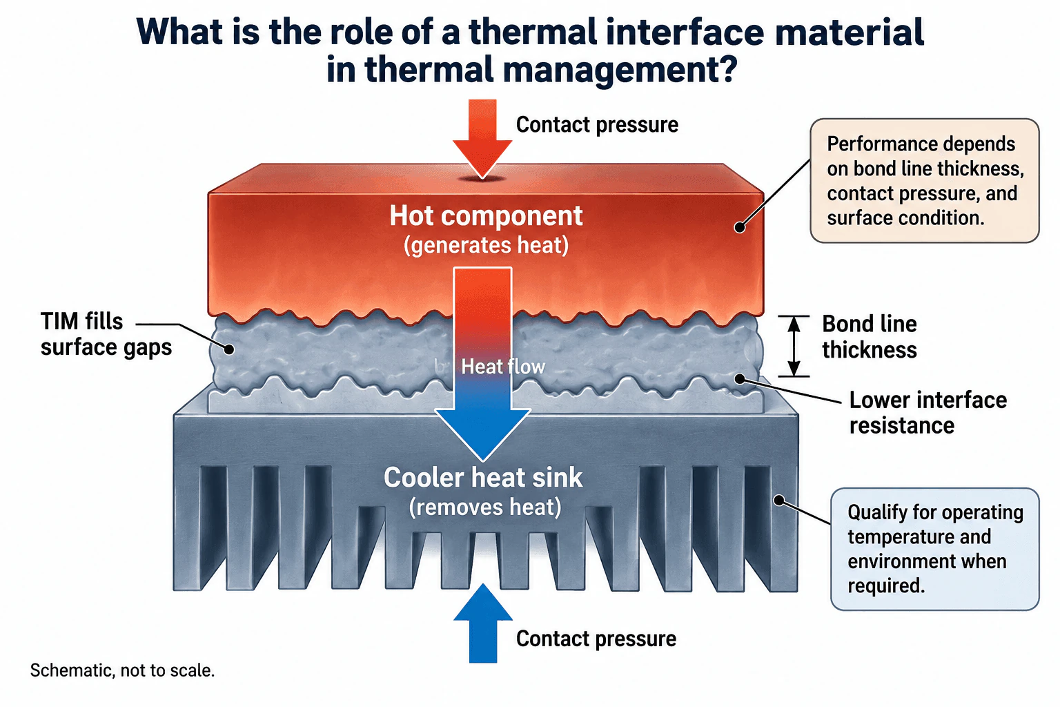
A thermal interface material, or TIM, improves heat transfer between mating surfaces such as a hot component and a heat sink. Real surfaces are not perfectly flat, so microscopic gaps can trap air and increase interface thermal resistance. The TIM conforms to those surface irregularities and replaces much of that poorly conducting air with a better thermal path. Actual performance depends on the assembled bond line thickness, contact pressure, surface condition, operating temperature, and environmental durability, so catalog thermal conductivity alone does not define interface performance.
Detailed Explanation
A thermal interface material sits between a heat generating component and a cooler surface such as a heat sink. Its main role is to improve thermal contact. Even surfaces that appear smooth contain microscopic roughness and gaps. Those gaps can contain air, which adds resistance to heat flow. A conformable TIM fills much of that space and provides a more effective path for heat to move from the hot component into the cooler heat sink.
Useful Questions to Ask the Interviewer
What are the heat source, cooling surface, and expected operating temperature range?
What bond line thickness, contact pressure, and surface condition are expected after assembly?
Does the interface need qualification for thermal cycling, pump out, outgassing, corrosion, aging, or another environmental exposure?
How to Explain It in an Interview
Start by defining the physical heat path: heat moves from the hot component, through the TIM, and into the cooler heat sink. The TIM matters because the two solid surfaces do not make perfect contact across their full apparent area.
The first design objective is good surface conformity. The TIM fills microscopic surface gaps and reduces the contribution of trapped air to interface thermal resistance.
Next, evaluate the assembled interface rather than only the bulk material property. Bond line thickness matters because a longer conduction path usually adds resistance. Contact pressure matters because it can improve conformity and actual contact, but allowable pressure depends on the component, TIM, and mechanical design. Surface finish, flatness, contact geometry, and assembly tolerances also affect the final interface condition.
Material selection should consider thermal conductivity together with mechanical and environmental behavior. Depending on the application, relevant properties can include thermal expansion, anisotropy, heat capacity, mass, manufacturability, compatibility, and stability across the required temperature range.
Qualification is separate from basic conduction reasoning. When relevant to the material and environment, the assembled interface should be evaluated for thermal cycling, pump out, dry out, outgassing, corrosion, and aging. Initial thermal performance alone does not demonstrate retained performance after environmental exposure.
The key conclusion is that a TIM lowers interface thermal resistance by improving contact between mating surfaces. Its real performance is an assembly property controlled by the material, bond line thickness, contact pressure, surface condition, geometry, tolerances, temperature range, and environment. Catalog conductivity is useful for material characterization, but it should not be treated as the complete thermal performance of the assembled interface.
Why Interviewers Ask This
Interviewers want to see whether the candidate understands that thermal interface performance depends on the assembled interface, not only on a material conductivity value. A strong answer should connect surface conformity, bond line thickness, contact pressure, surface condition, operating temperature, and environmental exposure to resistance along the heat path.
Common interview mistakes
Common mistakes include saying only that a TIM has high thermal conductivity, ignoring microscopic surface gaps, treating catalog conductivity as the assembled interface performance, overlooking bond line thickness and contact pressure, assuming more pressure is always better, and ignoring environmental effects when thermal cycling, pump out, dry out, outgassing, corrosion, or aging are relevant.
Interview tip
Explain the answer as a heat path: hot component, imperfect surface contact, TIM filling surface gaps, lower interface resistance, then cooler heat sink. Then state that bond line thickness, contact pressure, surface condition, operating temperature, assembly tolerances, and environmental qualification determine whether the interface performs as intended.
Interviewer may ask next
How would you validate that a selected TIM is performing correctly in the assembled system?
I would validate the complete interface under representative assembly conditions rather than relying only on a catalog conductivity value. I would confirm the actual bond line thickness, contact geometry, contact pressure, and surface condition, then measure thermal performance across the interface under the required operating temperatures. If environmental qualification is required, I would repeat or compare the measurements after relevant thermal cycling, aging, or other exposure to verify that the interface retains acceptable performance.
What changes if the required bond line becomes thicker because of assembly tolerances?
A thicker bond line generally increases the thermal resistance contributed by the TIM layer, so the material and interface design may need to be reconsidered. I would check whether a more suitable gap filling material can accommodate the tolerance while maintaining contact, review the achievable contact pressure and surface conformity, and evaluate the assembled interface resistance. The selection should balance thermal performance with the mechanical tolerance instead of choosing a material only from its conductivity value.
22. How do you compare thermal grease, pads, and phase change interface materials?Thermal Materials And InterfacesHard
Short Interview Answer (30-60 seconds)
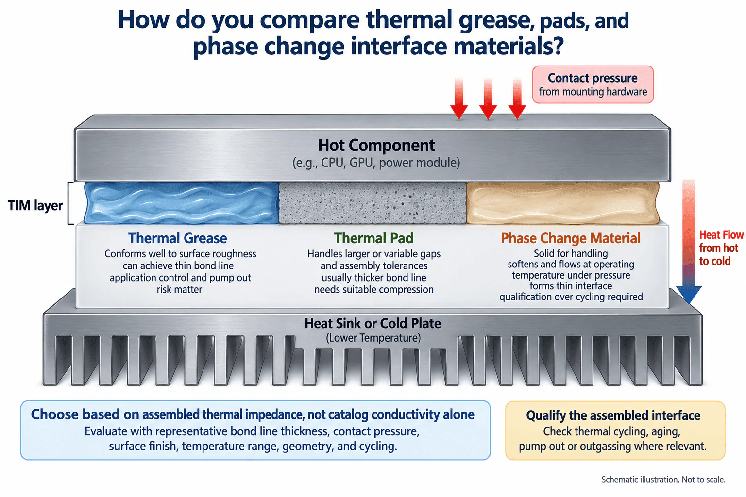
I compare thermal grease, pads, and phase change materials by the thermal performance of the assembled interface, not conductivity alone. Grease conforms well to surface roughness and can achieve a very thin bond line, but application control and pump out during thermal cycling can matter. Pads are useful for larger or variable gaps and assembly tolerances, but they usually create a thicker bond line and need suitable compression. Phase change materials are solid for handling, then soften at their designed operating temperature under pressure and conform to the surfaces. For all three, I would compare representative bond line thickness, contact pressure, surface finish, temperature range, gap geometry, and qualification results.
Detailed Explanation
All three materials sit in the same heat path: hot component, thermal interface material, then heat sink or cold plate. Their purpose is to reduce the thermal penalty caused by imperfect contact between the mating surfaces. The correct comparison is therefore based on the assembled interface under realistic mechanical and thermal conditions.
Useful Questions to Ask the Interviewer
What gap, surface geometry, and assembly tolerance must the interface accommodate?
What contact pressure and operating temperature range are available in the assembled system?
What reliability or environmental exposures must the interface survive, such as thermal cycling, aging, pump out, or outgassing?
How to Explain It in an Interview
First, define the heat path and the actual assembly conditions. I would compare each material using representative contact area, bond line thickness, contact pressure, surface finish, temperature range, and gap tolerance.
Thermal grease conforms very well to microscopic surface roughness and can form a very thin bond line. That can produce low assembled interface resistance when the surfaces are closely spaced and properly clamped. The tradeoff is process control. Dispense amount, spread, surface condition, and long term stability matter, and pump out during thermal cycling can be a failure mechanism.
A thermal pad is a solid, compressible interface that is useful when the gap is larger or varies because of assembly tolerances. It is easy to place and can accommodate dimensional variation. The tradeoff is that its compressed bond line is usually thicker than a grease interface, so the actual thermal resistance must be evaluated at the expected thickness and compression.
A phase change interface material is solid during handling and softens at its designed phase change temperature. With suitable contact pressure, it can flow and wet the mating surfaces, producing a thin conformal interface. Its temperature range must support the intended phase change behavior, and the assembled interface should be qualified through relevant thermal cycling and aging tests.
I would not select among these materials from catalog conductivity alone. Conductivity is only one material property. The final decision should use assembled thermal impedance or resistance measured under representative bond line thickness, pressure, surface finish, geometry, and temperature. Reliability checks should cover material specific risks such as pump out, dry out, outgassing, corrosion, or aging when those mechanisms are relevant.
So the practical comparison is: grease for very thin conformal interfaces, pads for larger gaps and tolerance accommodation, and phase change materials when solid handling plus thermal softening is useful. The final choice must be validated in the representative assembled interface.
Why Interviewers Ask This
Interviewers want to see whether the candidate can compare thermal interface materials using assembled interface performance rather than catalog conductivity alone. The key judgment is how bond line thickness, contact pressure, surface condition, gap tolerance, operating temperature, manufacturability, and reliability affect the complete heat path.
Common interview mistakes
Common mistakes are choosing a material from conductivity alone, ignoring bond line thickness and contact pressure, using grease to compensate for a large structural gap, evaluating a pad without considering its compressed thickness, assuming a phase change material will soften adequately at the actual operating temperature, and skipping qualification for thermal cycling, aging, pump out, or outgassing where relevant.
Interview tip
Organize the answer around the assembled heat path. State the gap, contact pressure, surface condition, and temperature range first. Then compare grease, pads, and phase change materials under those same conditions. Finish by explaining that representative assembled interface performance is more meaningful than catalog conductivity by itself.
Interviewer may ask next
How would you validate the selected thermal interface material before release?
I would build representative interfaces using the expected surfaces, contact area, bond line thickness, contact pressure, geometry, and operating temperature range. I would measure thermal performance in the assembled condition, then repeat the measurement after relevant environmental exposure such as thermal cycling or aging. I would also inspect for material specific failure mechanisms such as grease pump out, dry out, phase change material migration, outgassing, or corrosion where those mechanisms are applicable. The selection is supported only if the interface maintains acceptable thermal performance under the intended conditions.
What changes if the mechanical gap varies significantly across production units?
Tolerance accommodation becomes more important. A thermal pad may become attractive because its thickness and compression can accommodate a larger or variable gap. Grease is intended for a thin interface and is generally not the preferred way to fill a large structural gap. A phase change material can conform after softening, but its available thickness, contact pressure, and operating temperature still have to match the assembly. I would evaluate the candidates at the minimum and maximum expected gap and pressure rather than only at the nominal condition.
23. How do you calculate the heat transfer area required for a heat exchanger?Heat Exchangers And Cooling SystemsMedium
Short Interview Answer (30-60 seconds)
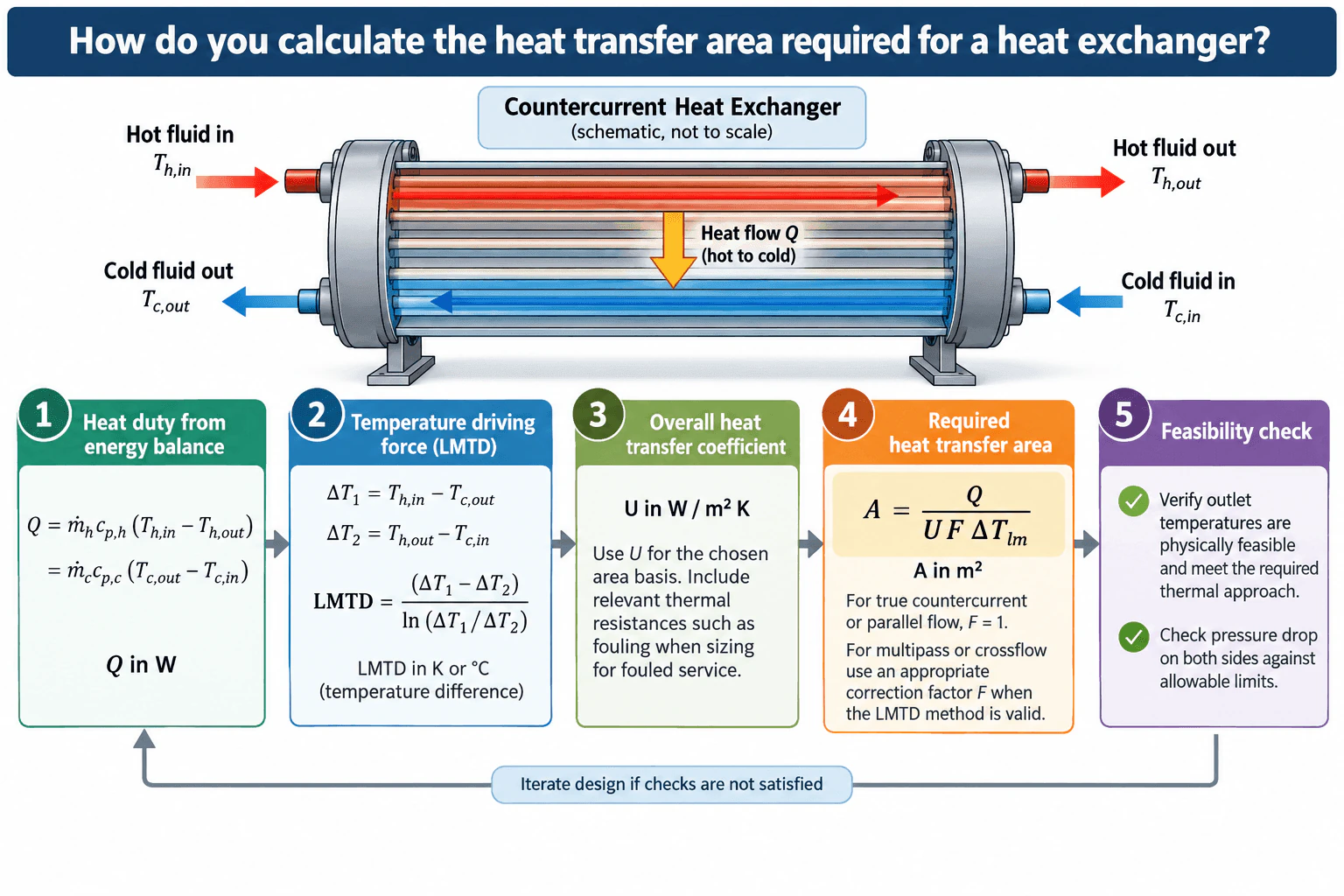
First calculate the required heat duty from an energy balance, such as Q = ṁh cp,h (Th,in − Th,out), and confirm that the cold side gives the same duty. For known inlet and outlet temperatures, calculate the log mean temperature difference from the two terminal temperature differences. Then use A = Q ÷ (U F ΔTlm), where U is the overall heat transfer coefficient and F is the LMTD correction factor for the selected flow arrangement. Finally, verify that the outlet temperatures are physically feasible and that pressure loss on both sides remains within the allowable limits.
Detailed Explanation
The required heat transfer area comes from matching the required heat duty to the available temperature driving force and the exchanger's overall ability to transfer heat. For the countercurrent arrangement shown in the approved diagram, calculate the heat duty first, then the two terminal temperature differences, the log mean temperature difference, the overall heat transfer coefficient, and finally the required area.
Useful Questions to Ask the Interviewer
Are the hot and cold inlet and outlet temperatures known, or are some outlet temperatures part of the design result?
What flow arrangement should I assume, such as true countercurrent, parallel flow, or a multipass shell and tube arrangement?
Should U include fouling resistance, and what pressure loss limits apply to each fluid stream?
How to Explain It in an Interview
Physical Method
Start with the energy balance. For sensible heat with approximately constant specific heat, Q = ṁh cp,h (Th,in − Th,out) and Q = ṁc cp,c (Tc,out − Tc,in). The hot side heat loss and cold side heat gain should agree within the assumptions of the problem. If mass flow is in kg/s and specific heat is in J/(kg K), Q is in W.
Calculate the terminal temperature differences for the actual flow arrangement, where h and c denote the hot and cold streams:
Then calculate ΔTlm = (ΔT1 − ΔT2) / ln(ΔT1/ΔT2). For equal positive terminal differences, use the limiting value ΔTlm = ΔT1 = ΔT2. A temperature difference has the same numerical value in K and °C.
For ideal counterflow or parallel flow, F = 1 when using that arrangement's corresponding temperature differences. For applicable multipass or crossflow arrangements, use the appropriate correction factor with the reference counterflow LMTD.
Next select the overall heat transfer coefficient U in W/(m² K). Use U on the same area basis as A and include the relevant convection, wall conduction, and fouling resistances for the service.
Calculate the required heat transfer area from A = Q ÷ (U F ΔTlm).
Assumptions And Checks
Verify that the specified outlet temperatures are physically possible and provide the required thermal approach. Confirm the energy balance independently on both fluid sides. Then calculate pressure loss on each side and compare it with the allowable limits. A thermally adequate area can still be unacceptable if the required flow geometry causes excessive pressure loss.
Engineering Reasoning
The required area increases when Q increases, when U decreases because of weaker heat transfer or fouling, or when the effective temperature driving force decreases. If outlet temperatures are unknown, the effectiveness NTU method can be more convenient because it uses heat capacity rates and exchanger effectiveness instead of requiring all outlet temperatures in advance. Final sizing should also be checked across the expected operating envelope, including fouled and part load conditions.
Why Interviewers Ask This
Interviewers want to see whether you can convert a required heat duty into a physically reasonable exchanger area using an energy balance, the correct temperature driving force, an appropriate overall heat transfer coefficient, and the required flow arrangement correction. They also want to see whether you check temperature feasibility, fouling assumptions, and pressure loss instead of treating the area equation as the complete design.
Common interview mistakes
Common mistakes include using an arithmetic mean temperature difference instead of LMTD, pairing the wrong terminal temperatures, mixing inconsistent units, using a U value based on a different area definition, ignoring fouling, omitting the correction factor when the exchanger arrangement requires it, assuming physically impossible outlet temperatures, and sizing for thermal duty without checking pressure loss.
Interview tip
Explain the sequence clearly: heat duty, terminal temperature differences, LMTD, overall heat transfer coefficient, correction factor, required area, then feasibility and pressure loss checks. Define each symbol and keep the units visible. This demonstrates both the calculation and the physical reasoning behind the design.
Interviewer may ask next
How would you validate the calculated exchanger area before using it for a real design?
I would repeat the heat balance independently on the hot and cold sides and check dimensional consistency. I would verify the assumed fluid properties and U value for the expected temperatures, flow regime, materials, and fouling condition. I would confirm the flow arrangement and correction factor, then calculate pressure loss on both sides. I would also evaluate clean, fouled, nominal, and part load operating conditions. The area calculation gives the required thermal surface estimate, but detailed geometry, hydraulic performance, manufacturability, and applicable design requirements still need separate verification.
What happens to the required area if the allowable temperature approach becomes smaller?
A smaller thermal approach generally reduces the effective temperature driving force. If Q, U, and the flow arrangement remain otherwise unchanged, the denominator in A = Q ÷ (U F ΔTlm) becomes smaller, so the required heat transfer area increases. A tighter approach can therefore require a larger exchanger and can also affect pressure loss, pump or fan power, and the practical operating envelope.
24. What is thermal design margin?Thermal DesignEasy
Short Interview Answer (30-60 seconds)
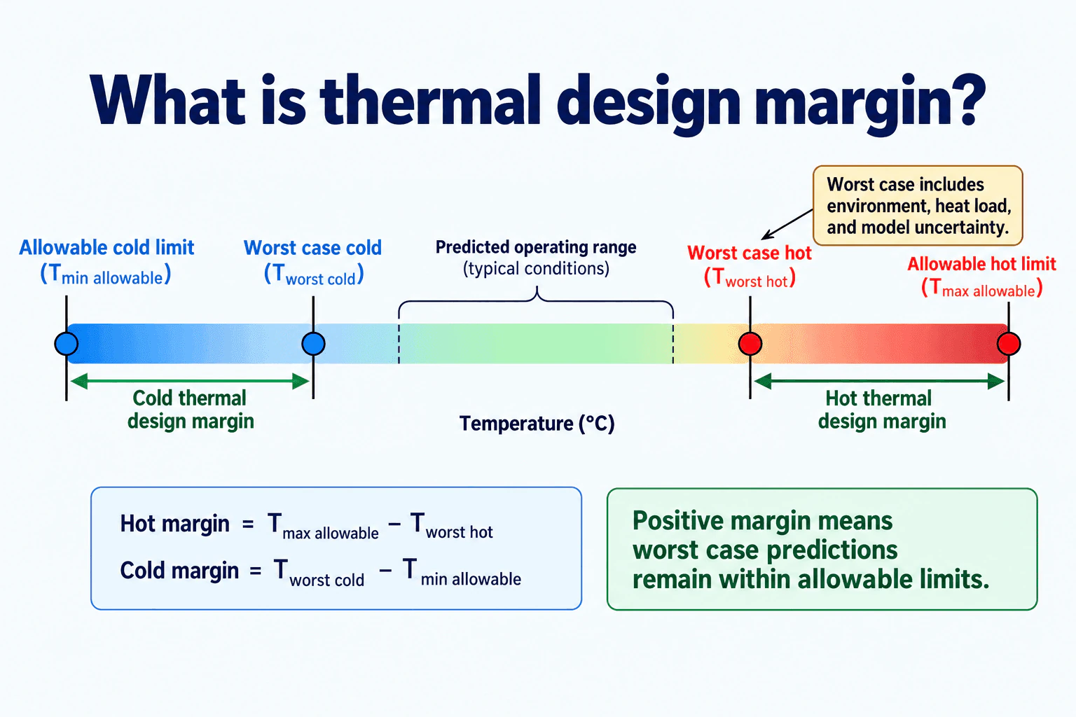
Thermal design margin is the temperature difference between an allowable temperature limit and the corresponding worst case predicted temperature. Hot margin equals the maximum allowable temperature minus the worst case hot prediction. Cold margin equals the worst case cold prediction minus the minimum allowable temperature. A positive margin means the worst case prediction remains inside the allowable limit. A negative margin means the prediction is outside that limit.
Detailed Explanation
Thermal design margin shows how much temperature separation remains between the worst case predicted temperature and the applicable allowable temperature limit. It is evaluated separately for hot and cold conditions. The typical predicted operating range can help describe normal behavior, but thermal design margin is determined from the worst case hot and cold predictions, not from typical temperatures.
Useful Questions to Ask the Interviewer
Are the stated limits the allowable operating temperature limits for the component or system being evaluated?
Do the worst case predictions already include environmental, heat load, and model uncertainty?
Should the margin be checked only for steady operation, or also for startup, transient, and degraded operating conditions?
How to Explain It in an Interview
Physical Method
I would first identify the allowable cold limit, T_min allowable, and the allowable hot limit, T_max allowable. Then I would determine the corresponding worst case cold temperature, T_worst cold, and worst case hot temperature, T_worst hot, for the same physical boundary and operating conditions.
The hot thermal design margin is:
Hot margin = T_max allowable − T_worst hot
The cold thermal design margin is:
Cold margin = T_worst cold − T_min allowable
These are temperature differences and can be reported in °C or K.
Engineering Reasoning
The worst case predictions should include the conditions and uncertainties that can drive the design toward its hottest and coldest temperatures. In the diagram, these include environment, heat load, and model uncertainty.
If the hot margin is positive, the worst case hot prediction is below the allowable hot limit. If the cold margin is positive, the worst case cold prediction is above the allowable cold limit. If both margins are positive, the worst case predictions remain within the allowable temperature range. A zero margin means the prediction reaches the applicable limit. A negative margin means the predicted temperature lies outside that allowable limit.
Assumptions And Checks
I would confirm that the allowable limits and worst case predictions refer to the same component, operating state, boundary, and temperature definition. I would also confirm that uncertainty is included consistently and is not omitted or counted twice.
Finally, I would check the relevant worst case hot and cold conditions rather than relying on the typical operating range. The design should be judged against the applicable allowable limits and the uncertainty included in the worst case predictions.
Why Interviewers Ask This
Interviewers want to see whether you understand how allowable temperature limits are compared with worst case predicted temperatures, how uncertainty affects those predictions, and how to determine whether adequate temperature separation remains on both the hot and cold sides.
Interviewer may ask next
How would you validate that the thermal design margin is trustworthy?
I would verify that each allowable limit and predicted temperature refers to the same component, physical boundary, and operating condition. I would review the environmental assumptions, heat loads, boundary conditions, and model uncertainty used to create the worst case hot and cold predictions. I would also compare the predictions with an independent calculation or representative thermal test evidence when available and check the relevant startup, transient, steady, and degraded conditions.
What would you do if the hot thermal design margin became negative after the heat load increased?
A negative hot margin means T_worst hot is above T_max allowable. I would first update the worst case prediction using the new heat load and confirm the boundary conditions and uncertainty. Then I would evaluate changes that reduce the worst case hot temperature, such as lowering heat generation, reducing thermal resistance, improving heat spreading, increasing passive heat rejection, adding or increasing active cooling, or changing the operating duty cycle. I would compare those options against mass, volume, power, reliability, and interface constraints before selecting a design change.
25. How do you define temperature limits and heat loads before selecting a thermal architecture?Thermal DesignMedium
Short Interview Answer (30-60 seconds)
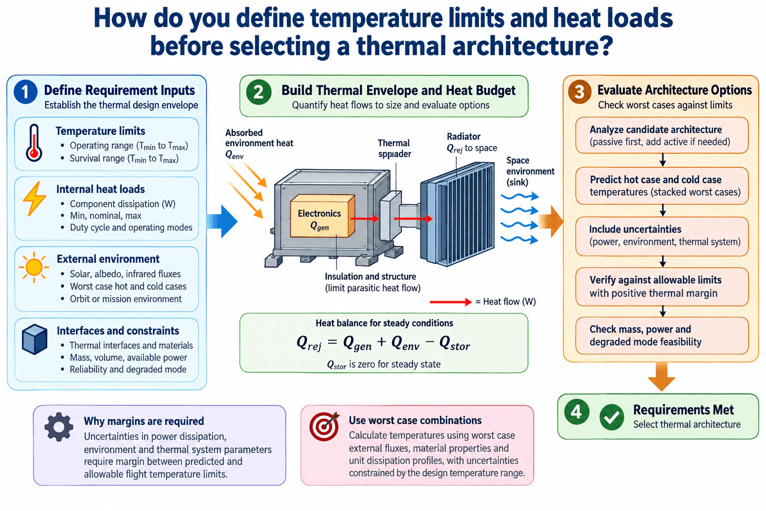
I define the thermal design envelope before selecting the architecture. First I document operating and survival temperature limits for each critical component. Then I build a heat budget using minimum, nominal, and maximum internal dissipation, duty cycles, operating modes, and environmental heat input. I also define thermal interfaces plus mass, volume, available power, reliability, and degraded mode constraints. I evaluate candidate passive and active approaches against worst hot and cold cases, include uncertainty, and require positive thermal margin before selecting the architecture.
Detailed Explanation
Before selecting a thermal architecture, I first define the temperatures the system must maintain and the heat that must be generated, absorbed, stored, transferred, and rejected. This creates a traceable thermal design envelope that can be used to judge every candidate architecture consistently.
Useful Questions to Ask the Interviewer
What are the operating and survival temperature limits for the critical components?
What operating modes, duty cycles, and worst hot and cold environments must the system cover?
What mass, volume, power, reliability, and degraded mode constraints apply?
How to Explain It in an Interview
Physical Method
I start by defining the physical boundary and operating conditions. For every critical component, I record its allowable operating and survival temperature limits. These limits become the acceptance criteria for the thermal design.
Next I build a traceable heat budget. Internal heat generation, Qgen, comes from component power dissipation and should be defined for minimum, nominal, and maximum operating conditions. Duty cycle and operating mode are important because heat generation can change substantially between standby, startup, nominal operation, and peak operation.
I then define environmental heat input, Qenv. For a space application this can include absorbed solar, albedo, and infrared radiation. I also identify the thermal interfaces, structure, insulation, heat spreading paths, available radiator area, and the intended thermal sink.
For the defined thermal system, assuming no additional energy-transfer terms, the balance is: dE_stored/dt = Qgen + Qenv − Qrej.
Here, Qgen is internal heat generation, Qenv is environmental heat input, and Qrej is heat rejection, all in watts. E_stored is stored energy in joules; dE_stored/dt is its rate of change, also in watts.
At steady state, dE_stored/dt = 0, so Qrej = Qgen + Qenv. Stored energy itself need not be zero. During a transient, an imbalance changes the stored energy and can change component temperatures.
Engineering Reasoning
Only after defining these inputs do I evaluate candidate architectures. I first determine whether passive methods such as conductive heat spreading, insulation, interfaces, and radiators can keep temperatures within limits. If passive control is insufficient, I consider active methods such as heaters, controlled airflow, or coolant flow where appropriate.
I evaluate worst hot and worst cold combinations, then include uncertainty in power dissipation, environment, interfaces, and other thermal parameters. Predicted temperatures must remain within allowable limits with positive thermal margin.
Assumptions And Checks
I also check mass, volume, available power, reliability, and degraded mode feasibility. A design that satisfies temperature limits but violates another system constraint is not acceptable.
I select the thermal architecture only when the heat budget, worst case temperatures, uncertainty, margins, and system constraints are mutually consistent. Detailed transfer derivations, CFD setup, and test execution are separate follow on activities.
Why Interviewers Ask This
Interviewers want to see whether I can convert system requirements into a traceable thermal design envelope before choosing hardware. The key judgment is whether I define allowable temperatures, heat loads, operating modes, environment, interfaces, uncertainty, and system constraints first, then compare candidate thermal architectures against worst hot and cold conditions.
Interviewer may ask next
How would you validate that the temperature limits and heat loads used for architecture selection are credible?
I would trace every temperature limit and heat load to an approved requirement, component specification, electrical power estimate, operating mode, or environmental definition. I would verify units, physical boundaries, minimum and maximum conditions, and the energy balance. I would also perform sensitivity or uncertainty checks on dominant heat loads and thermal interfaces. If a reasonable uncertainty changes the architecture decision, I would treat that input as a design risk and obtain better evidence before final selection.
What would change if the available power budget became much smaller?
A smaller power budget would make powered thermal control less attractive. I would revisit the architecture trade study and place more emphasis on passive heat spreading, conductive interfaces, insulation, radiator effectiveness, and operating mode management. I would then repeat the worst hot and cold analysis because reduced heater, fan, pump, or other active control capability can reduce thermal margin and affect degraded mode behavior. The selected architecture would still need to satisfy the temperature limits and revised power constraint.
26. How do you allocate thermal margin when heat loads and boundary conditions are uncertain?Thermal DesignHard
Short Interview Answer (30-60 seconds)
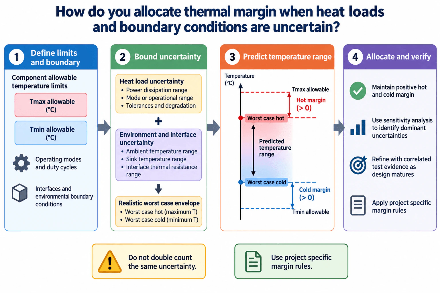
I first define the allowable hot and cold temperature limits, operating modes, duty cycles, interfaces, and environmental boundaries. Then I bound the credible uncertainty in heat loads and in environmental or interface conditions and combine them into realistic worst case hot and cold conditions. I predict the resulting temperature range and calculate hot margin as Tmax allowable minus worst case hot temperature, and cold margin as worst case cold temperature minus Tmin allowable. Both margins must remain positive and meet any project specific margin rule. I then use sensitivity analysis and correlated test evidence to reduce the dominant uncertainties without double counting them.
Detailed Explanation
Thermal margin should be allocated from the temperature requirements backward rather than by adding an arbitrary allowance everywhere. I establish a defensible worst case temperature envelope from uncertain heat loads and boundary conditions, then compare that envelope with the allowable hot and cold limits.
Useful Questions to Ask the Interviewer
Are the heat loads provided as nominal values, bounded ranges, or another uncertainty description?
Which environmental and interface conditions define the required worst case hot and cold conditions?
Does the project define a specific thermal margin or uncertainty rule?
How to Explain It in an Interview
1. Define limits and boundaries
I start with Tmin allowable and Tmax allowable for the component, using °C or K consistently. I also define operating modes, duty cycles, environmental boundaries, sink conditions, and thermal interfaces. This establishes the physical boundary and the conditions that the thermal design must satisfy.
2. Bound the uncertainty
For heat generation, I identify the credible power dissipation range in W, including mode variation, tolerances, and relevant degradation. For boundary conditions, I bound quantities such as ambient temperature, sink temperature, and interface thermal resistance when they affect the design.
Each uncertainty source stays traceable so the same physical uncertainty is not counted twice.
3. Build realistic worst case envelopes
I propagate those bounded inputs through the thermal model using combinations that can physically occur together. The worst case hot condition is the highest credible predicted component temperature. The worst case cold condition is the lowest credible predicted temperature.
I would not automatically put every input at its extreme if those extremes cannot occur at the same time. Operating state, correlation, and physical constraints determine the credible combinations.
4. Calculate thermal margin
Hot margin = Tmax allowable − Tworst hot
Cold margin = Tworst cold − Tmin allowable
Both margins should remain greater than zero and should also satisfy any project specific margin rule.
5. Allocate effort using sensitivity
If margin is small, I use sensitivity analysis to identify whether heat load, ambient or sink temperature, or interface resistance is driving the result. I focus design changes, characterization, or testing on the dominant contributors instead of applying equal conservatism everywhere.
6. Refine and verify
As the design matures, better characterization and correlated test evidence can reduce justified uncertainty. I update the thermal model and margins consistently while maintaining traceability. If the hot or cold margin becomes negative, the thermal architecture, interface design, operating limits, or uncertainty assumptions must change before the requirement is considered satisfied.
Why Interviewers Ask This
Interviewers want to see whether I can turn uncertain heat loads and boundary conditions into traceable worst case thermal conditions, calculate hot and cold margin against allowable temperature limits, avoid counting the same uncertainty twice, and use analysis and evidence to focus design effort on the uncertainties that matter most.
Interviewer may ask next
How would you validate that the allocated thermal margin is credible?
I would trace every important uncertainty to its source, confirm that the worst case combinations are physically possible, perform sensitivity analysis on the dominant inputs, and compare model predictions with independent analytical checks or correlated thermal test evidence. I would also confirm that all required operating modes are covered and that no uncertainty has been counted more than once.
What would you do if the worst case hot temperature exceeds the allowable maximum?
I would first identify the dominant contributor through sensitivity analysis. Depending on the result, I could reduce the heat load, lower the ambient or sink boundary temperature, reduce interface thermal resistance, improve passive heat spreading or rejection, add active cooling, or change the duty cycle. I would then repeat both the worst case hot and cold checks because a change that improves the hot condition can affect cold margin, power, mass, reliability, or control requirements.
27. What is a thermocouple?Thermal Testing And ValidationEasy
Short Interview Answer (30-60 seconds)
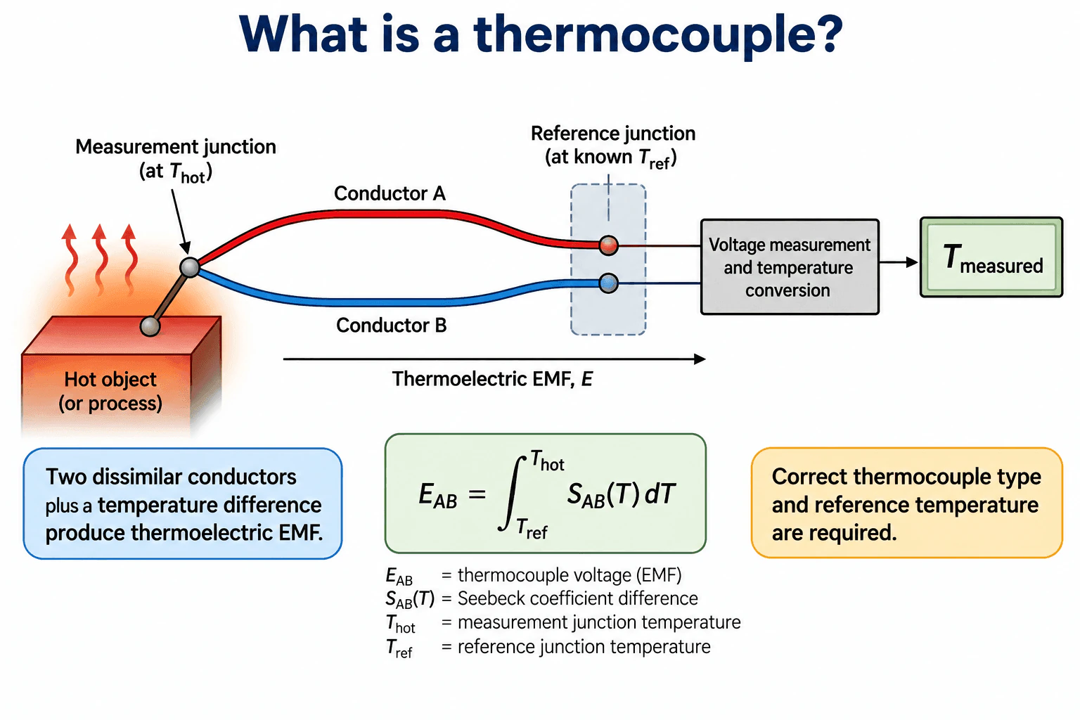
A thermocouple is a temperature sensor made from two dissimilar electrical conductors joined at a measurement junction. When the measurement junction and the reference junction are at different temperatures, a thermoelectric EMF is produced. A measurement system reads that voltage and uses the correct thermocouple calibration together with the reference junction temperature to determine the measurement junction temperature.
Detailed Explanation
A thermocouple uses two dissimilar conductors, shown conceptually as Conductor A and Conductor B, joined at a measurement junction. That junction is placed in thermal contact with the hot object or process whose temperature is being measured. The other ends connect to the measurement system at a reference junction region.
The temperature difference between the measurement junction and the reference junction produces a thermoelectric EMF. A useful conceptual expression is E_AB = ∫ from T_ref to T_hot of S_AB(T)dT. Here, E_AB is the thermocouple voltage, T_hot is the measurement junction temperature, T_ref is the reference junction temperature, and S_AB(T) is the difference in Seebeck coefficients for the two conductors.
The voltage alone does not directly give the measurement junction temperature. The instrument measures the thermocouple voltage, accounts for the reference junction temperature, and applies the calibration relationship for the selected thermocouple type. It then reports the measured temperature.
Useful Questions to Ask the Interviewer
Which thermocouple type and temperature range are being considered?
Is the focus on the sensing principle or on practical installation and measurement accuracy?
Should reference junction compensation and uncertainty be discussed?
How to Explain It in an Interview
Start with the construction. A thermocouple consists of two dissimilar conductors joined at a measurement junction. The junction is placed in thermal contact with the object or process being measured.
Then explain the signal. If the measurement junction and the reference junction are at different temperatures, the thermocouple produces a small thermoelectric EMF. The magnitude of that voltage depends on the conductor pair and the temperatures involved.
Next explain the measurement path. The measurement system reads the thermocouple voltage, determines the reference junction temperature, and uses the correct calibration for that thermocouple type to calculate the measurement junction temperature.
For test work, I would also consider calibration, junction placement, thermal contact, wire routing, electrical noise, thermal gradients, and acquisition system uncertainty. Poor placement or poor thermal contact can make the reported temperature differ from the temperature of interest.
The main idea is that a thermocouple does not measure temperature from voltage alone. It measures a thermoelectric voltage created by two dissimilar conductors, and accurate temperature conversion requires both the correct thermocouple type and the reference junction temperature.
Why Interviewers Ask This
Interviewers want to know whether the candidate understands how a thermocouple senses temperature, why two dissimilar conductors are required, how thermoelectric EMF is produced, why the reference junction temperature matters, and what practical factors affect measurement accuracy.
Common interview mistakes
Common mistakes include saying that a thermocouple produces voltage from temperature alone, ignoring the reference junction temperature, using the wrong calibration for the thermocouple type, placing the measurement junction where it does not represent the desired temperature, assuming perfect thermal contact, and overlooking calibration and measurement uncertainty.
Interview tip
Explain the principle in three steps: two dissimilar conductors form the measurement junction, a temperature difference produces thermoelectric EMF, and the measurement system uses that voltage together with the reference junction temperature and the correct thermocouple calibration to determine the measured temperature.
Interviewer may ask next
Why does the reference junction temperature matter?
The thermocouple voltage depends on the temperature relationship between the measurement junction and the reference junction, not on the measurement junction temperature alone. The measurement system therefore needs the reference junction temperature so it can correctly convert the measured EMF into the measurement junction temperature.
What can make a thermocouple measurement inaccurate even when the correct thermocouple type is used?
Important causes include poor thermal contact, incorrect junction placement, heat conduction along the wires, electrical noise, calibration error, reference junction error, local temperature gradients, and acquisition system uncertainty. These effects should be considered when estimating measurement uncertainty in a thermal test.
28. What is thermal model correlation?Thermal Testing And ValidationEasy
Short Interview Answer (30-60 seconds)
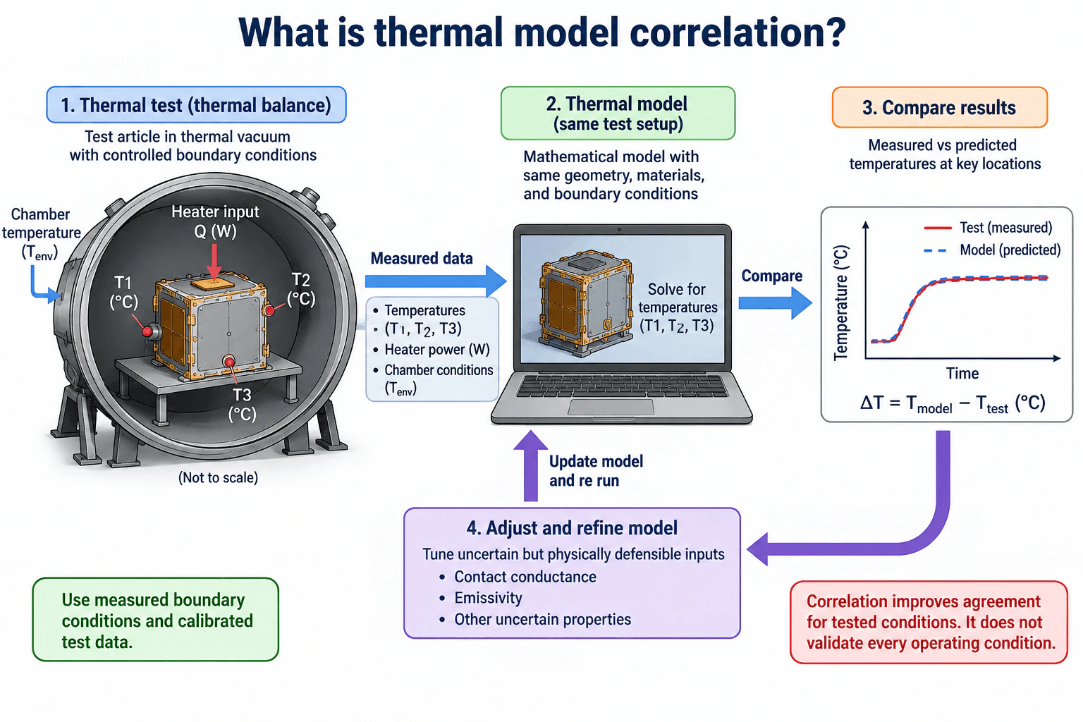
Thermal model correlation is the process of comparing temperatures predicted by a thermal model with temperatures measured during a controlled thermal test, then refining uncertain but physically defensible model inputs so the model better represents the tested hardware and conditions. For example, I would use measured temperatures, heater power, and chamber boundary conditions from a thermal balance test, run the model with the same setup, compare predicted and measured temperatures at matching locations, investigate the differences, and adjust justified parameters such as contact conductance or emissivity. Good agreement supports the model for the tested conditions, but it does not prove accuracy for every operating condition.
Detailed Explanation
Thermal model correlation connects a mathematical thermal model to measured behavior from a controlled test. The goal is not simply to force the model to match the data. The goal is to identify justified differences between the model and the physical hardware, then refine uncertain inputs while preserving a physically credible representation.
Useful Questions to Ask the Interviewer
What measured boundary conditions and thermal test data are available for the correlation?
What temperature agreement or other measurable criteria define acceptable correlation?
Which model parameters have enough physical uncertainty to justify adjustment?
How to Explain It in an Interview
Physical Method
I would first define the physical boundary, test objective, operating condition, and measured inputs. In the diagram, the example is a thermal balance test performed in a thermal vacuum chamber. The test provides measured temperatures T1, T2, and T3 in °C, heater input Q in W, and chamber temperature Tenv in °C.
I would run the thermal model using the same geometry, materials, heater power, and boundary conditions represented by the test. Predicted temperatures are then compared with measured temperatures at the corresponding sensor locations. A useful residual is ΔT = Tmodel − Ttest. A positive value means the model predicts a higher temperature than the measurement, while a negative value means it predicts a lower temperature.
If the differences are larger than the defined correlation criteria, I would first check sensor calibration, sensor placement, measured boundary conditions, repeatability, measurement uncertainty, and heat balance closure. I would not immediately tune the model simply to reduce the error.
After those checks, uncertain parameters can be adjusted when there is a physical basis. The diagram shows examples such as contact conductance and emissivity. I would change only defensible parameters, rerun the model, and check whether agreement improves across the relevant measured locations rather than only one sensor.
Assumptions And Checks
The model and test must represent the same operating case. Measured boundary conditions and calibrated test data should be used where available. Parameter adjustments should stay within physically credible ranges. Measurement uncertainty, repeatability, heat balance closure, and independent evidence should be considered when judging the result.
Engineering Reasoning
A correlated model has stronger evidence that it represents the tested hardware under the tested conditions. Correlation is not the same as qualification or acceptance testing. It also does not prove that the model is accurate for every operating condition. Additional operating cases or independent test evidence may be required before applying the model outside the range represented by the correlation data.
Why Interviewers Ask This
Interviewers want to know whether the candidate understands how measured thermal test data is used to assess and refine a thermal model while keeping parameter changes physically defensible and recognizing that correlation is different from qualification, acceptance, and validation across all operating conditions.
Common interview mistakes
Common mistakes include adjusting parameters only to force agreement, ignoring measurement uncertainty or sensor placement, using assumed boundary conditions when measured values are available, comparing temperatures at nonmatching locations, overlooking poor heat balance closure, and treating agreement with one test as proof that the model is valid for every operating condition. Another mistake is confusing thermal model correlation with qualification or acceptance testing.
Interview tip
Explain correlation as a disciplined loop: reproduce the measured test conditions in the model, compare measured and predicted temperatures at matching locations, investigate discrepancies, adjust only uncertain parameters with a physical basis, rerun the model, and state the limits of the resulting correlation. Mentioning measurement uncertainty, heat balance closure, and the distinction between correlation, qualification, and acceptance demonstrates sound thermal test judgment.
Interviewer may ask next
How would you decide whether a model parameter should be adjusted during correlation?
I would adjust a parameter only after confirming that the test data, sensor calibration, sensor placement, boundary conditions, and model setup are credible. The parameter should have real uncertainty and a physical connection to the observed temperature difference. For example, uncertain contact conductance can affect heat transfer across an interface, while uncertain emissivity can affect radiative heat transfer. I would keep the value within a physically defensible range, rerun the model, and verify whether the change improves agreement across multiple relevant measurements without creating contradictions elsewhere.
What would you do if the correlated model matches one thermal balance test but must predict a different operating condition?
I would not assume that the original correlation automatically applies to the new condition. I would check whether the new heat loads, boundary temperatures, interfaces, material behavior, and dominant heat transfer paths remain represented by the original correlation evidence. I would compare the model with another operating case, independent measurement, or additional test data when available. If the new condition introduces important behavior that was not exercised in the original test, I would treat the prediction as having greater uncertainty until additional evidence supports it.
29. How do you distinguish qualification testing from acceptance testing?Thermal Testing And ValidationHard
Short Interview Answer (30-60 seconds)
Qualification testing demonstrates that a design can meet its specified thermal and functional requirements across the defined qualification conditions. It is normally performed on representative hardware using conditions intended to demonstrate design capability and expose weaknesses. Acceptance testing verifies that production hardware or an accepted sampling of production hardware conforms to approved requirements and workmanship expectations. The same chamber, DUT, thermocouples, programmable power supply, DAQ, and analysis system can support both, but the objective, hardware population, environmental severity, duration, sampling, acceptance criteria, and failure disposition are defined separately.
Detailed Explanation
Qualification asks whether the design can satisfy its thermal requirements under the defined qualification conditions. Acceptance asks whether production hardware conforms to the approved requirements and workmanship expectations. They can use similar equipment and measurements, but they are not interchangeable forms of evidence.
Useful Questions to Ask the Interviewer
What operating and environmental conditions define the required thermal envelope?
Is the test intended to qualify the design, accept production hardware, or correlate a thermal model?
What measurable temperature, electrical performance, stability, and failure criteria define a pass?
How to Explain It in an Interview
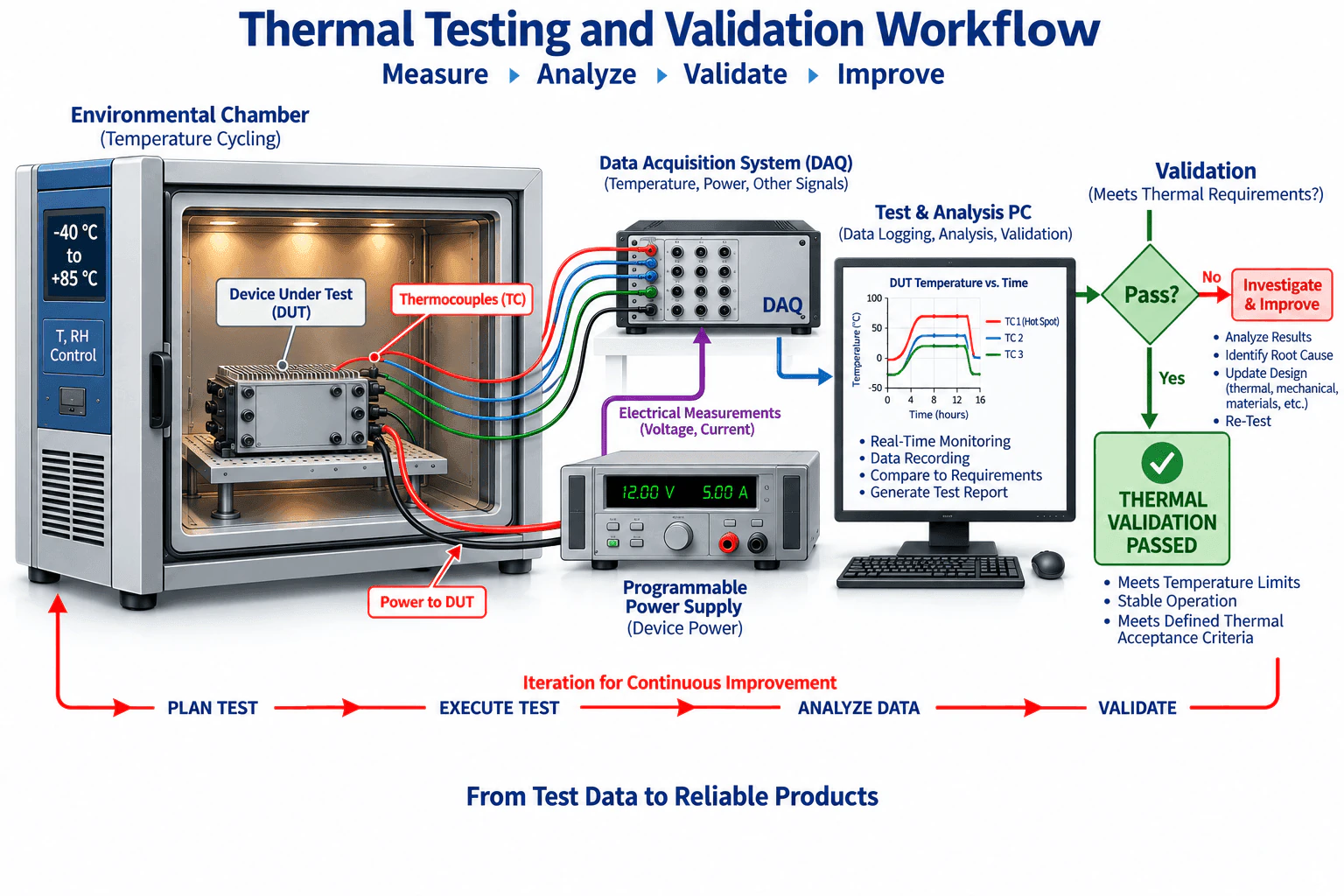
I would first define the physical boundary, test objective, operating cases, environmental conditions, and measurable acceptance criteria. A typical setup places the DUT in an environmental chamber, powers it with a programmable supply, measures critical locations with calibrated thermocouples or other suitable sensors, records temperature and electrical measurements through a DAQ, and compares the results with predefined requirements on the analysis system.
For qualification, I use representative hardware and operating cases that exercise the required design envelope. I define chamber conditions, DUT power state, sensor locations, dwell conditions, thermal cycling conditions, and pass criteria before the test. The purpose is to demonstrate design capability under the specified qualification conditions. If the result does not meet a requirement, I analyze the data, identify the root cause, update the design or test understanding when justified, and repeat the required evidence before declaring thermal validation passed.
For acceptance, I use the approved production test procedure to determine whether a unit or lot conforms to established requirements. Acceptance conditions can be shorter or less severe than qualification when the governing requirements allow it because the goal is to detect production and workmanship problems without unnecessarily consuming hardware life. I would never assume the severity, duration, or sampling plan. Those values must come from the applicable program requirements.
For both test types, I verify sensor calibration and placement, record chamber and DUT conditions, monitor temperature and electrical behavior, document repeatability, and account for measurement uncertainty when it could affect the pass decision. The result is compared with the defined thermal acceptance criteria rather than judged informally.
I also keep model correlation separate. Agreement between a thermal model and one test can increase confidence for that tested condition, but it does not by itself qualify the hardware, accept production hardware, or validate every operating case.
Why Interviewers Ask This
The interviewer is evaluating whether I understand that qualification and acceptance testing answer different engineering questions, use different evidence, and require predefined objectives and criteria. They also want to see whether I can define the physical test boundary, operating conditions, instrumentation, uncertainty, failure disposition, and limits of the conclusions.
Common interview mistakes
Common mistakes include treating qualification and acceptance as the same test, automatically applying full qualification severity to every production unit, defining pass criteria after reviewing the data, failing to control DUT operating state or sensor locations, ignoring measurement uncertainty, confusing model correlation with hardware qualification, and assuming that one successful thermal test validates every operating condition.
Interview tip
State the distinction first: qualification demonstrates design capability against defined qualification requirements, while acceptance verifies that production hardware conforms to approved requirements. Then explain the shared execution path through test planning, chamber exposure, DUT operation, thermocouple and electrical measurements, DAQ recording, analysis, pass criteria, failure investigation, and retest when required.
Interviewer may ask next
How would measurement uncertainty affect a qualification or acceptance decision?
I would evaluate the uncertainty of the complete measurement chain, including sensor calibration, DAQ accuracy, sensor placement, thermal contact, chamber behavior where relevant, and repeatability. I would then apply the governing decision rule when comparing the measured result with the requirement. If uncertainty is large enough that compliance cannot be established confidently, I would improve the measurement method, repeat the test, or obtain additional evidence rather than declaring a pass without support.
What changes if acceptance testing is consuming too much product life?
I would review the acceptance objective and determine which stresses are actually needed to reveal production defects. Subject to the governing requirements, the acceptance profile could use fewer cycles, shorter dwell periods, or reduced environmental severity while retaining the measurements needed to detect workmanship and functional problems. I would not simply reuse the full qualification profile, and any revised acceptance procedure would require documented technical justification and evidence that it still meets its screening objective.
30. How do you select measurement locations for a thermal test?Thermal Testing And ValidationMedium
Short Interview Answer (30-60 seconds)
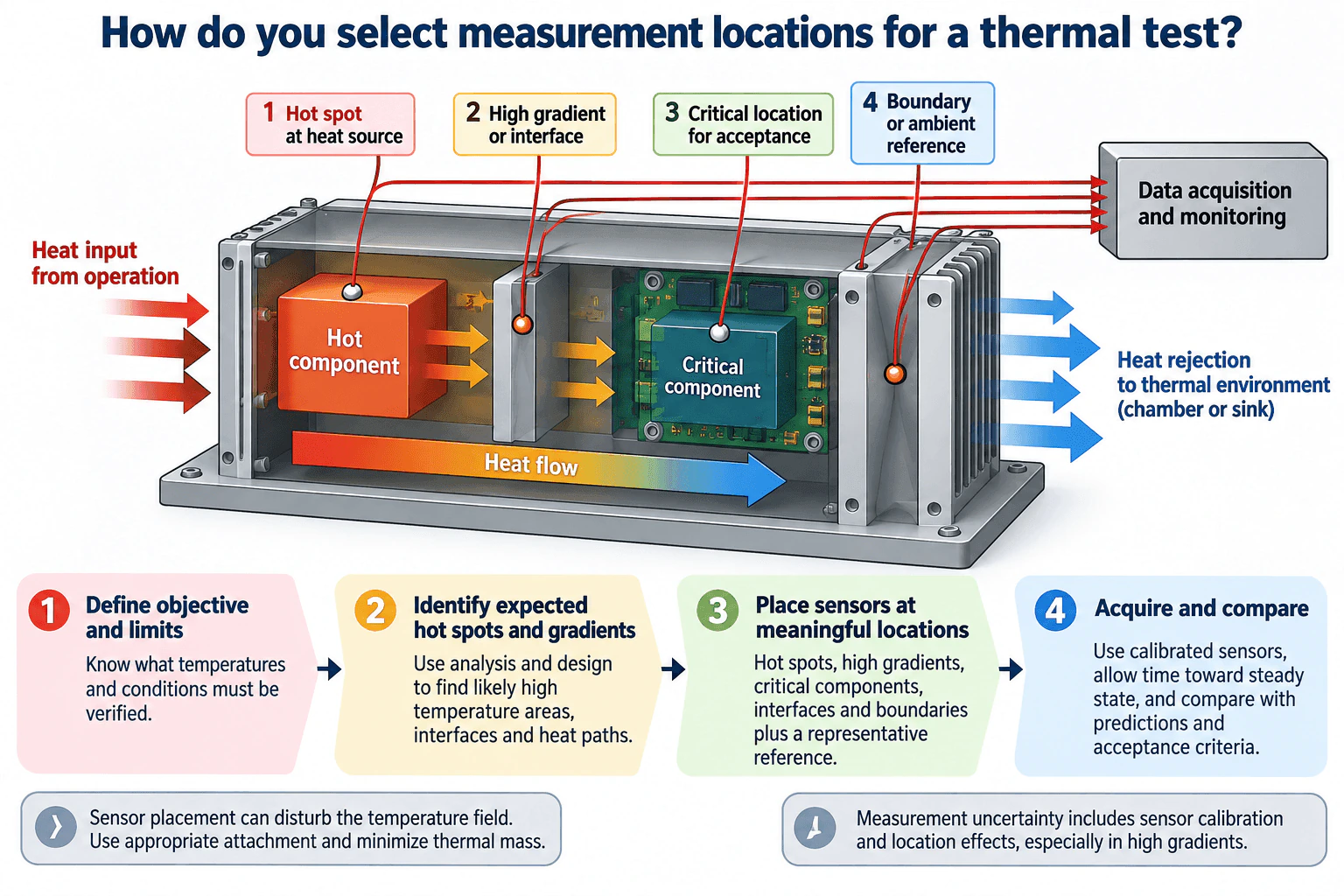
I start by defining the test objective and the temperatures or conditions that must be verified. Then I use the expected heat path and thermal analysis to identify likely hot spots, high gradient regions, critical components, important interfaces, and representative boundary or ambient locations. I place calibrated sensors only where each measurement answers a specific test question, while minimizing disturbance from the sensor, attachment, and wiring. Finally, I acquire data under representative conditions and compare the measurements with acceptance criteria and independent predictions while accounting for measurement and location uncertainty.
Detailed Explanation
Measurement locations should come from the test objective and expected thermal behavior, not from evenly spacing sensors across the hardware. Each location should answer a specific question about a hot spot, thermal gradient, critical component, interface, boundary condition, or model prediction.
Useful Questions to Ask the Interviewer
Is the main objective acceptance, qualification, thermal balance, or model correlation?
Which components, interfaces, or temperature limits are critical?
Which operating cases and environmental boundary conditions must be represented?
How to Explain It in an Interview
First, I define the objective, physical boundary, operating conditions, and measurable acceptance criteria. Acceptance testing, qualification testing, and model correlation have different purposes, so I would not treat agreement from one test as validation of every operating condition.
Next, I follow the expected heat path from the heat source toward the thermal environment. I use design information and thermal analysis to identify likely hot spots, regions with high temperature gradients, important interfaces, and critical components. Those become the primary measurement locations.
I also place a representative boundary or ambient sensor. That reference is important because the measured component temperature depends on both internal heat input and the surrounding thermal environment. The diagram therefore includes four key location types: a hot spot at the heat source, a high gradient or interface location, a critical location used for acceptance, and a boundary or ambient reference.
Sensor type and installation also matter. Thermocouples and RTDs are common contact measurements, while infrared thermography can provide spatial temperature information when surface and viewing conditions are suitable. Contact sensors can disturb the local temperature through attachment, thermal mass, and wiring, so I minimize those effects and use calibrated instrumentation.
The measurements are routed to the data acquisition system. For a steady state test, I allow the hardware to approach the required thermal condition before comparing results. For a transient test, I select locations and acquisition settings that capture the required temperature response.
Finally, I compare measurements with acceptance criteria and independent predictions at equivalent physical locations and boundary conditions. I include calibration uncertainty and location uncertainty, especially where gradients are steep. If the purpose is model correlation, a good match increases confidence for the tested condition, but it does not prove the model is valid for all loads, environments, or operating cases.
Why Interviewers Ask This
Interviewers want to see whether you can translate a thermal test objective into defensible measurement locations that capture hot spots, important gradients, critical component temperatures, interfaces, and representative boundary conditions while accounting for sensor disturbance, calibration, uncertainty, and comparison with independent thermal predictions.
Common interview mistakes
Common mistakes include placing sensors only where they are physically convenient, missing expected hot spots or high gradient interfaces, omitting a representative boundary or ambient reference, attaching sensors in a way that changes the local temperature, using uncalibrated instrumentation, comparing measurements with model locations that are not physically equivalent, and treating agreement from one operating condition as validation of every condition.
Interview tip
Explain the selection logic in the same order as the heat path shown in the test setup: define what must be verified, identify hot spots and gradients, instrument critical components and interfaces, add a representative boundary measurement, then compare calibrated measurements with criteria and predictions while accounting for uncertainty.
Interviewer may ask next
How would you validate that your selected measurement locations are sufficient?
I would check that every critical requirement and important thermal path has an associated measurement or independent observation. I would confirm that the heat source, important interfaces, critical components, and representative boundary conditions are covered. I would also compare the measured temperature pattern with independent predictions, review repeatability and uncertainty, and add or relocate measurements if unexpected gradients or unexplained heat balance differences appear.
How would your sensor placement change if you expected a very steep temperature gradient?
I would place additional measurements on both sides of the gradient so the temperature change is resolved instead of represented by one point. I would pay close attention to exact sensor position, attachment, thermal mass, wiring, and calibration because small location errors can produce larger temperature errors in a steep gradient. I would also make sure any model comparison uses equivalent physical locations.
More questions load as you scroll
Disclaimer: This interview guide is for educational and informational purposes only. It is designed to help readers prepare, but it does not guarantee any interview result, hiring decision, offer, or outcome. Interview questions, hiring criteria, and preferred answers can vary by employer, interviewer, industry, location, and time. All answers, examples, and explanations in this guide are suggested examples for interview preparation, not definitive answers or instructions for professional practice. They are based on research and judgment, are provided without warranties of any kind, and should be adapted to the question, role, and applicable laws and professional requirements. Diagrams are simplified illustrations intended to highlight the main concepts and their relationships; actual situations, systems, and practices may be more complex. Alternative approaches may be equally valid or better suited to a particular question, context, or interviewer. To the fullest extent permitted by applicable law, the contributors and publisher are not liable for decisions made, actions taken, or losses incurred based on this guide.
State Laws and Professional Responsibilities: Laws and requirements governing an occupation vary by state and jurisdiction. You are responsible for checking the current laws, licensing requirements, and scope-of-practice rules that apply to your location and role, and for ensuring that your answers and actions comply with them. Adapt examples in this guide to those requirements. This guide is not legal advice.
Content Accuracy and Verification: To the fullest extent permitted by applicable law, we do not represent or warrant that interview guides, questions, answers, examples, or diagrams are accurate, complete, current, error-free, or suitable for any particular purpose. You are responsible for independently reviewing and verifying the information before relying on it.