189 DevOps Engineer Interview Questions & Answers

105 top • 14 Amazon • 12 Apple • 15 Google • 9 Meta • 14 Microsoft • 8 Netflix • 12 NVIDIA

DevOps Engineer icon

Questions with Detailed ExplanationsWith Detailed Explanations

(Last Updated: September 1, 2026)

11. How would you design production release governance with separation of duties?DevOpsHard

Question Details

A regulated service must promote one already-tested artifact from staging to production. Design protected source and release branches, immutable artifact identity, automated evidence, quality gates, independent approval, least-privilege deployment execution, emergency access, audit history, and rollback. Explain how the flow prevents an approver or deployer from silently rebuilding or substituting the release.

Short Interview Answer (30-60 seconds)

I would build the artifact once in CI, store it immutably, and identify it by its exact digest. Staging and production must use that same digest. Protected branches control source changes. Automated tests, scans, SBOM data, provenance, signatures, and build records create evidence tied to the digest. An independent release manager reviews that evidence and approves promotion. A separate deployment identity can fetch and deploy only the approved digest with least privilege. It cannot rebuild the application, modify source, change the approval, or substitute another artifact. Every approval, deployment, emergency action, and rollback is recorded in tamper evident audit history.

Detailed Explanation

The goal is to move one tested release from staging into production without allowing anyone to secretly change it. Different people receive different responsibilities. One person can change the product, another person decides whether the release is allowed, and another person performs the deployment. The exact item being released is recorded so everyone can prove what moved. Checks happen before approval. Important actions are recorded. Special emergency access is temporary and reviewed. If the release causes a problem, the team can return to the previously approved version.

Useful Questions to Ask the Interviewer
  1. Which regulatory or audit requirements must this release process satisfy?
  2. Must every production release have a human approval?
  3. What recovery time is expected if production validation fails?
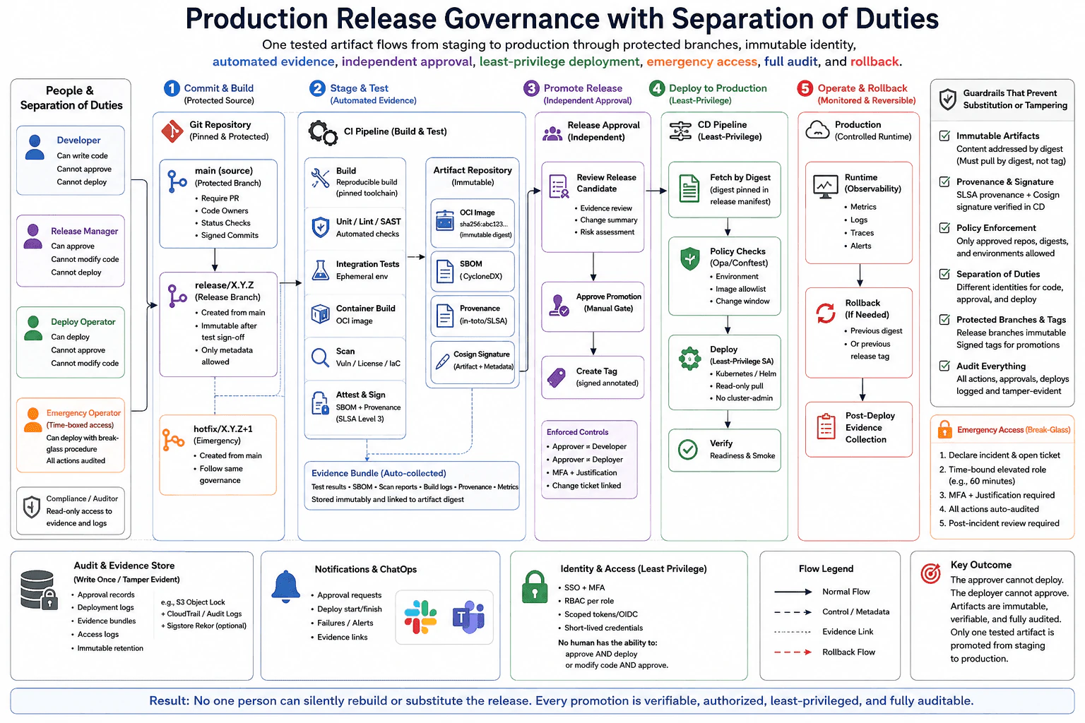
How would you design production release governance with separation of duties? diagram
How to Explain It in an Interview

I would start with protected Git branches. Developers can change code through reviewed pull requests, but they cannot approve or deploy production releases. The main source branch requires review, ownership rules, status checks, and signed commits. A protected release branch is created from approved main branch history. After testing and sign off, it becomes immutable except for controlled release metadata.

CI performs the build using a pinned toolchain. It runs unit tests, linting, static security checks, integration tests, vulnerability checks, license checks, and infrastructure policy checks. CI then creates the OCI image, SBOM, provenance statement, and artifact signature. The artifact repository stores the image immutably by digest. Automated evidence such as test results, scan reports, build logs, provenance, and metrics is stored immutably and linked to that digest.

Staging deploys the exact digest. After staging validation, an independent release manager reviews the release candidate, evidence, change summary, risk, and change ticket. The approver is not the developer or deployer. MFA and justification are required. Approval creates a signed release tag or release record that points to the approved artifact.

The CD pipeline uses a separate least privilege identity. It fetches the artifact by digest from the release manifest. Policy checks validate the target environment, image allowlist, and change window. The deployment role can pull the approved image and deploy through Kubernetes or Helm, but it has no cluster administrator rights and cannot modify source, approval records, or the artifact. Readiness and smoke checks verify the deployment.

Production observability collects metrics, logs, traces, and alerts. If needed, rollback redeploys the previous approved digest or previous approved release tag. Approval records, deployment logs, evidence bundles, access logs, and rollback events are written to a tamper evident audit store. Emergency access requires an incident ticket, a time bound elevated role, MFA, justification, automatic auditing, and a required review after the incident. This prevents an approver or deployer from silently rebuilding or substituting the release because approval and deployment are both bound to the same immutable artifact identity.

Why Interviewers Ask This

Interviewers ask this question to test whether a candidate can design a controlled production release process for a regulated service. They want to see clear separation between people who change code, people who approve a release, and people who execute deployment. They also evaluate knowledge of protected branches, immutable artifact identity, automated evidence, quality gates, least privilege access, emergency controls, audit history, and rollback.

Common interview mistakes

Common mistakes include rebuilding the application during production deployment, promoting a mutable image tag instead of an immutable digest, allowing the approver to modify code or trigger a new build, allowing the deployer to approve the release, and giving the deployment identity broad administrator access. Other mistakes include storing evidence without linking it to the artifact digest, letting release branches change after sign off, skipping signature or provenance verification, allowing an unapproved image outside the allowlist, providing permanent emergency administrator access, and calling rollback safe without keeping the previous approved artifact available.

Interview tip

Explain one artifact identity from start to finish. First say who can change code, who can approve, and who can deploy. Then explain that CI builds once and that staging, approval, production deployment, audit evidence, and rollback all reference the same immutable digest. Finish with least privilege, emergency access, monitoring, and tamper evident audit history. This makes the separation of duties easy for the interviewer to verify.
Interviewer may ask next
What happens if production deployment fails after the independent approval has already been recorded?

The existing approval remains evidence that a specific artifact was authorized, but the deployment failure must not trigger a silent rebuild. The CD system records the failed deployment and validation evidence. If rollback is required, it redeploys the previous approved digest or previous approved release tag. If the team needs a corrected build, CI creates a new immutable artifact with a new digest. That new artifact must pass the same tests, evidence collection, quality gates, independent approval, and promotion process.

How would you handle an urgent production incident when the normal release approval process is too slow?

I would use controlled break glass access rather than bypassing governance without a record. The operator first declares an incident and opens a ticket. A time bound elevated role is granted with MFA and justification. The operator performs only the minimum recovery action needed, such as redeploying a known good approved digest. Every action is automatically audited, and a review is required after the incident. The tradeoff is faster recovery in exchange for temporarily broader access, so the role must remain narrow, short lived, and fully traceable.

12. What is the cloud shared responsibility model, and how does responsibility change across IaaS, PaaS, and SaaS?Cloud InfrastructureEasy

Question Details

A team is moving the same business capability from self-managed virtual machines to a managed application platform and then to a software-as-a-service product. Identify which security and operational responsibilities stay with the customer, which move to the cloud provider, and which remain shared at each service-model boundary. Include data, identity, application configuration, operating systems, physical infrastructure, and compliance evidence.

Short Interview Answer (30-60 seconds)

At a high level, the shared responsibility model explains which cloud duties belong to the customer and which belong to the provider. The main challenge is that this boundary moves from IaaS to PaaS to SaaS. I would compare customer duties, provider duties, and shared duties across the same layers. The provider manages more as we move toward SaaS, while data and identity remain customer responsibilities. The trade-off is less operational work for the customer, but also less direct control.

Detailed Explanation

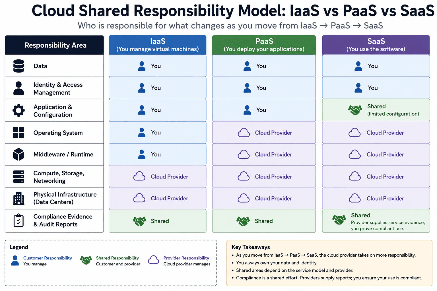
The question asks who is responsible for protecting and operating each part of a cloud service. The difficult part is that responsibility changes when the team moves from virtual machines to a managed application platform and then to SaaS. The customer gives more operational work to the cloud provider at each step. However, some duties still stay with the customer. The diagram compares the same areas across IaaS, PaaS, and SaaS. It shows customer responsibility, provider responsibility, and shared responsibility, including compliance evidence.

Useful Questions to Ask the Interviewer
  1. Are we using a provider-neutral shared responsibility model?
  2. Should I explain both security and operational responsibilities?
  3. Should compliance evidence be discussed separately from compliance duties?
What is the cloud shared responsibility model, and how does responsibility change across IaaS, PaaS, and SaaS? diagram
How to Explain It in an Interview
1. Start with the responsibility boundary

I would explain that cloud responsibility is not simply customer or provider. The boundary changes with the service model. In IaaS, the customer manages more of the software stack. In PaaS, the provider takes over more platform work. In SaaS, the provider manages even more of the service. This gives us a simple way to compare all three models.

2. Explain what stays with the customer

The customer remains responsible for business data in all three models shown. Identity and access management also stays with the customer. This includes deciding which users should have access and what permissions they receive. Moving to SaaS does not remove these duties. A provider can protect the service it operates, but the customer still controls who should access its data.

3. Show how application configuration changes

In IaaS, the customer manages the application and its configuration. The diagram shows the same customer responsibility in PaaS. In SaaS, this area becomes shared. The provider operates the software, while the customer controls the limited settings the SaaS product exposes. This means the customer can configure its use of the product without managing the software platform underneath it.

4. Show which technical layers move to the provider

For IaaS, the customer manages the operating system and the middleware or runtime. The provider manages compute, storage, networking, and the physical data centers. With PaaS, the operating system and middleware or runtime move to the provider. Those layers remain provider responsibilities in SaaS. Compute, storage, networking, and physical infrastructure are provider responsibilities in all three columns. This is why PaaS and SaaS reduce infrastructure work for the customer.

5. Explain compliance as shared work

Compliance evidence and audit work are shared across IaaS, PaaS, and SaaS. The provider can supply evidence about the service it operates, such as audit reports. The customer must still prove that its own use follows the required rules. The SaaS column makes this boundary explicit: the provider supplies service evidence, while the customer proves compliant use. The benefit of moving toward SaaS is less operational work. The downside is less direct control over provider-managed layers.

Practical Complexity & Trade-offs

The benefit is that the customer has less infrastructure work as the service moves from IaaS to PaaS to SaaS. The provider takes over the operating system, runtime, compute, storage, networking, and physical infrastructure at different boundaries. The downside is less direct control over those provider-managed layers. Data and identity still remain customer responsibilities in the diagram. Application configuration becomes shared in SaaS because the customer controls only the settings the product exposes. Compliance also remains shared. The provider supplies evidence about its service, while the customer must prove that its own configuration and use follow the required rules.

Why Interviewers Ask This

Interviewers ask this to see whether you understand where customer responsibility ends and provider responsibility begins. They want more than memorized definitions of IaaS, PaaS, and SaaS. A strong answer shows that you can follow how security and operational duties move across service models. It also shows whether you understand that data, identity, application configuration, infrastructure, and compliance can have different responsibility boundaries.

Interviewer may ask next
What changes if the team moves from IaaS to PaaS but still needs strong control over application configuration?

I would keep the same responsibility boundary shown in the diagram. Moving from IaaS to PaaS changes who manages the operating system and the middleware or runtime. Those duties move from the customer to the cloud provider. The application and its configuration still remain customer responsibilities in this design.

That means the team can continue controlling its application settings while avoiding operating-system patching and runtime maintenance. Data and identity also remain with the customer. Compute, storage, networking, and physical infrastructure continue to be provider responsibilities.

Compliance remains shared. The provider supplies evidence for the platform it operates, while the customer proves that its application, data handling, identity setup, and use of the platform meet the required rules.

The main downside is reduced control over the platform below the application. If the team needs operating-system changes or runtime behavior that the managed platform does not allow, PaaS may be more restrictive than IaaS.

How would you explain compliance responsibility when the team moves all the way to SaaS?

Compliance would still be shared even though the SaaS provider manages most of the technical layers shown in the diagram. The provider manages the operating system, middleware or runtime, compute, storage, networking, and physical infrastructure. The provider also supplies evidence about the service it operates.

The customer still has important duties. Business data and identity remain customer responsibilities. Application configuration is shared because the customer controls the limited settings exposed by the SaaS product, while the provider operates the service itself.

The customer must also prove that its own use follows the required rules. A provider audit report can show that the service has certain controls. It does not prove that the customer assigned the correct permissions or configured the product correctly.

The main downside is that the customer depends more on provider controls and provider evidence because it cannot directly manage or inspect the lower technical layers.

13. How would you lay out a three-tier application inside an AWS VPC?Cloud InfrastructureEasy

Question Details

Place internet-facing entry points, application servers, and a database into appropriate public or private subnets. Explain route tables, internet and outbound access, security-group boundaries, and which tiers may accept connections from each other.

Short Interview Answer (30-60 seconds)

At a high level, I would separate the application into public, application, and database tiers. The main challenge is allowing only the traffic each tier needs while keeping private systems off the public Internet. Users reach the Application Load Balancer in public subnets. The load balancer sends requests to application servers in private subnets, which connect to the database in isolated private subnets. NAT gateways give only the application tier outbound Internet access. The trade-off is more networking setup for stronger isolation.

Detailed Explanation

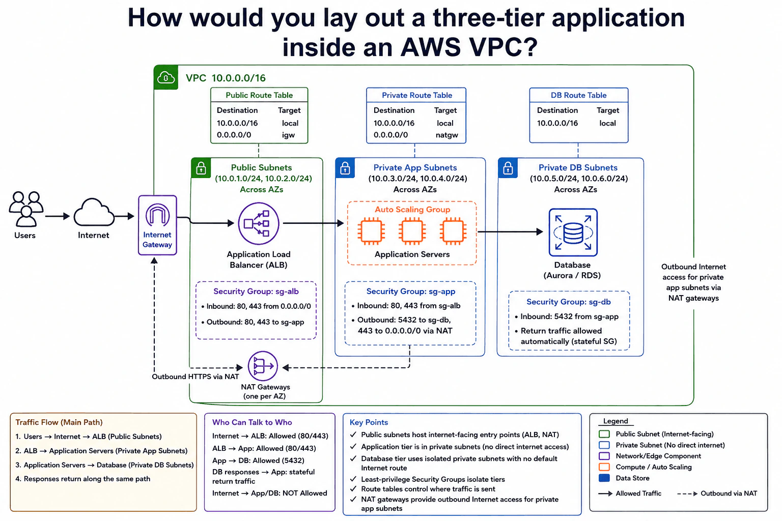
The goal is to place each part of the application where it can do its job without exposing more systems than necessary. Users need a public way to enter the application, but the application servers and database should not be directly reachable from the Internet. The design therefore separates the entry point, application work, and stored data. It also controls which parts may start connections to each other. The application tier gets controlled outbound Internet access, while the database stays isolated with no default Internet route.

Useful Questions to Ask the Interviewer
  1. Should the application servers need outbound Internet access for updates or external APIs?
  2. Should the database have any Internet access, or should it stay fully isolated?
  3. Do we need the application spread across multiple Availability Zones for higher availability?
How would you lay out a three-tier application inside an AWS VPC? diagram
How to Explain It in an Interview
1. Start with the three network tiers

I would start by separating the VPC into public, private application, and private database subnets. The VPC in the diagram is 10.0.0.0/16. Each tier has separate subnet ranges across Availability Zones.

The public subnets contain the Internet-facing Application Load Balancer and NAT gateways. The application servers stay in Private App Subnets. The database stays in isolated Private DB Subnets.

2. Explain how user traffic enters

Users first reach the Internet-facing Application Load Balancer. Its public subnets use a Public Route Table with 0.0.0.0/0 pointing to the Internet Gateway.

The load balancer security group, sg-alb, accepts ports 80 and 443 from 0.0.0.0/0. It sends allowed application traffic to sg-app. Internet users cannot directly connect to the application servers or database.

3. Follow the request through the application tier

The Application Load Balancer sends requests to the Application Servers in the Private App Subnets. Their security group, sg-app, accepts ports 80 and 443 only from sg-alb.

When the application needs data, it connects to sg-db on port 5432. The main request path is therefore Users to Internet, Internet to ALB, ALB to Application Servers, and Application Servers to Database. Responses return through the established connections.

4. Explain outbound Internet access

The application servers do not have direct Internet access. Their Private Route Table sends 0.0.0.0/0 traffic to NAT gateways in the Public Subnets.

The NAT gateways then use the public network path through the Internet Gateway. This lets the private application tier make outbound HTTPS connections without allowing Internet users to start connections directly to those servers.

The database is more isolated. Its DB Route Table contains only the local 10.0.0.0/16 route. It has no default route to the Internet or a NAT gateway.

5. Finish with security boundaries and the trade-off

The database security group, sg-db, accepts port 5432 only from sg-app. Security groups are stateful. This means return traffic for an allowed connection is automatically permitted without adding a separate response rule.

The benefit is strong separation between tiers. The downside is extra routing, subnet, NAT gateway, and security-group configuration. These controls take more work to manage, but they greatly reduce unnecessary Internet exposure.

Practical Complexity & Trade-offs

The benefit is strong network isolation. Only the Application Load Balancer is exposed to Internet users. Application servers stay private, and the database has no default Internet route. Security groups limit which tier may start a connection to the next tier. NAT gateways let private application servers make outbound Internet connections without making those servers public. The downside is more setup and more network pieces to manage. Route tables, NAT gateways, subnet placement, and security-group rules must all work together. We accept this extra complexity because it reduces unnecessary Internet exposure and keeps the database especially isolated.

Why Interviewers Ask This

Interviewers ask this question to see whether you understand basic cloud network boundaries, not whether you memorized AWS service names. They want to know if you can separate public and private systems, route traffic correctly, control connections with security groups, and keep a database away from direct Internet access. They also want to see whether you can explain the complete request path and the security trade-offs clearly.

Interviewer may ask next
What would you change if the application servers no longer needed any outbound Internet access?

I would keep the same three-tier layout, but I would remove the application tier's default route to the NAT gateways. The Application Load Balancer would still receive Internet traffic and send requests to the private Application Servers. Those servers could still connect to the Database over the local VPC network.

The main change is in the Private Route Table. It would no longer need 0.0.0.0/0 pointing to a NAT gateway. The Application Servers would then have no general Internet path, similar to the isolated database tier.

The security-group relationships would stay the same. sg-app would still accept application traffic from sg-alb. sg-db would still accept port 5432 from sg-app.

The benefit is even less Internet exposure and no need for outbound NAT from the application tier. The downside is that the application could not directly call external Internet APIs or download updates through that route.

What happens if someone tries to connect directly from the Internet to an application server or the database?

The connection should not be accepted by either private tier. The Application Servers and Database are in private subnets. The intended Internet entry point is the Application Load Balancer in the Public Subnets.

The security groups add another boundary. sg-app accepts ports 80 and 443 from sg-alb, not directly from Internet users. sg-db accepts port 5432 from sg-app, not from the Internet or the load balancer.

The Database has an additional routing boundary. Its DB Route Table contains only the local VPC route and has no default Internet route. The Application Servers can make outbound connections through NAT gateways, but NAT does not make them Internet-facing or allow unsolicited inbound Internet connections.

The benefit is strong tier isolation. The downside is that administration and troubleshooting must also use an approved private access path rather than direct Internet access.

14. How should an Azure workload access a secret without storing credentials?Cloud InfrastructureEasy

Question Details

A virtual machine or application service must read one secret from Azure Key Vault. Design the identity and authorization path using a managed identity, distinguish system-assigned from user-assigned identity, and define the smallest access boundary required.

Short Interview Answer (30-60 seconds)

At a high level, the workload should read its secret without storing any login credentials. The main challenge is proving which workload is calling while giving it only the access it needs. I would explain this in three steps: managed identity, token issuance, and Key Vault access. The workload gets a short-lived token from Microsoft Entra ID and uses it to read the secret. System-assigned identity fits one resource, while user-assigned identity can be reused across resources.

Detailed Explanation

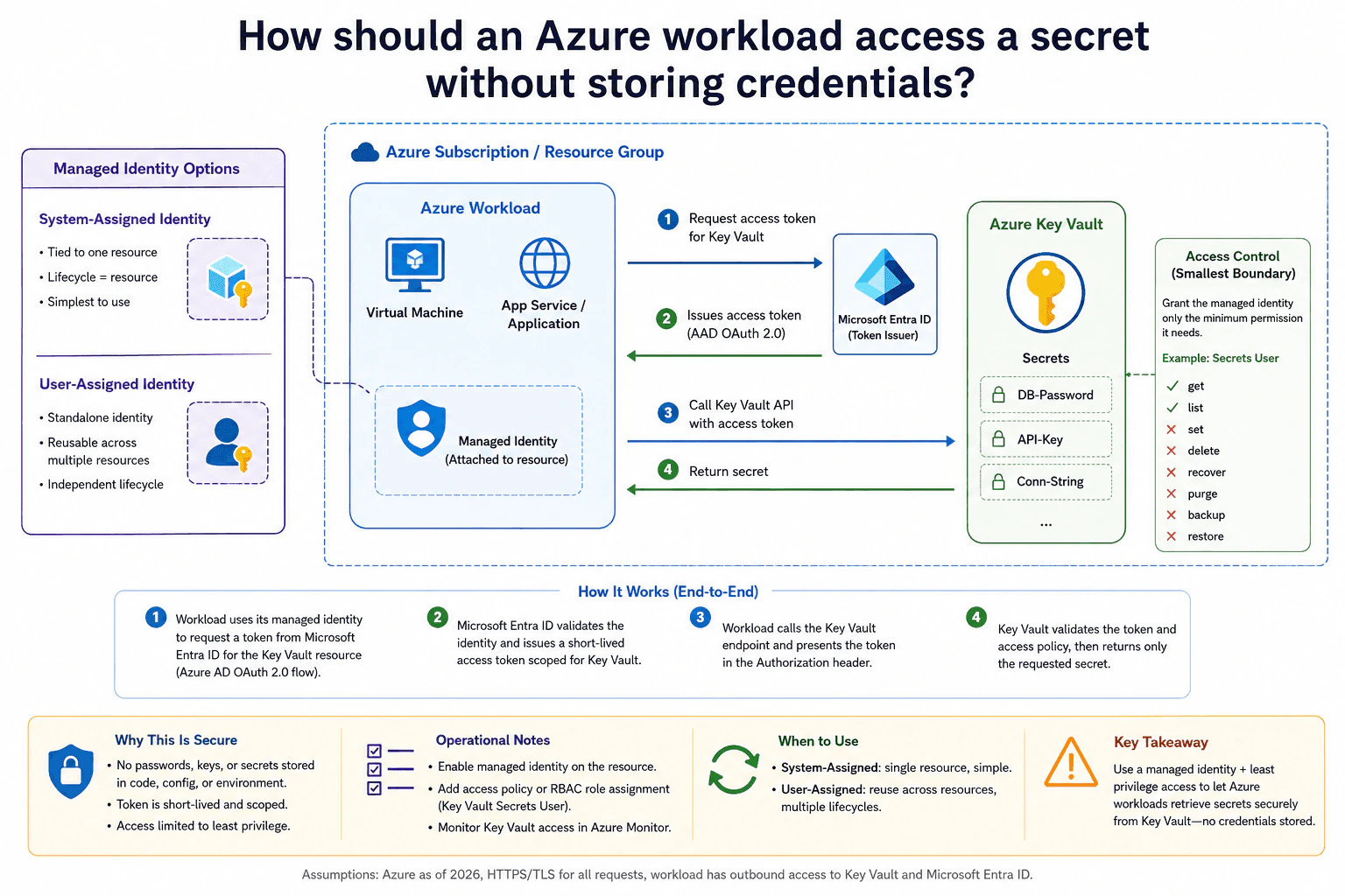
The goal is to let an Azure workload read a protected secret without saving a password, client secret, or access key inside the application. The main challenge is proving that the workload is trusted while limiting what it can read. The diagram solves this with a managed identity attached to a Virtual Machine or App Service. Microsoft Entra ID verifies that identity and provides a short-lived access token. The workload presents that token to Azure Key Vault, which checks authorization before returning the requested secret over HTTPS/TLS.

Useful Questions to Ask the Interviewer
  1. Is this identity used by only one Virtual Machine or App Service?
  2. Does the same identity need to be reused across several Azure resources?
  3. Does the workload need only one secret, or several secrets in the vault?
  4. Are we using Azure RBAC or a Key Vault access policy for authorization?
How should an Azure workload access a secret without storing credentials? diagram
How to Explain It in an Interview
1. Start with the managed identity

I would remove stored application credentials and enable a Managed Identity on the Azure workload. The workload can be a Virtual Machine or an App Service, as shown in the diagram.

A system-assigned identity is tied to one Azure resource. Its lifecycle follows that resource, which makes it simple for a single workload. A user-assigned identity is a separate Azure resource. It has its own lifecycle and can be attached to more than one workload.

2. Request a short-lived access token

When the workload needs the secret, it uses its managed identity to obtain an access token for Azure Key Vault. Microsoft Entra ID validates the managed identity and issues the token.

The token is short-lived. This means the application does not need a permanent password, client secret, or key for authentication. Azure manages the identity credentials behind the managed identity.

3. Call Azure Key Vault with the token

The workload calls the Azure Key Vault API and presents the access token. Key Vault validates the token and then checks what that managed identity is authorized to do.

If the identity has permission, Key Vault returns the requested secret over HTTPS/TLS. The application therefore retrieves the secret at runtime instead of storing it in source code, configuration files, or environment credentials.

4. Keep the access boundary as small as possible

I would give the managed identity only the secret-reading access that the workload actually needs. The diagram shows Key Vault Secrets User as the Azure RBAC example. With an access policy, I would grant Get and add List only when the application really needs it.

I would scope authorization as narrowly as practical. If the workload needs one secret, I would avoid broad management roles such as Owner or Contributor. The workload should be able to read the required secret, not manage the vault.

5. Choose the identity type and monitor access

For one workload with the same lifecycle as its Azure resource, I would normally choose a system-assigned identity. If several resources intentionally need the same identity, I would choose a user-assigned identity.

The benefit is that there are no application credentials to store or rotate. I would also enable Key Vault diagnostic logging and monitor access through Azure Monitor. That makes failed or unusual secret access visible without changing the main request path.

Practical Complexity & Trade-offs

The benefit is that the application does not store passwords, client secrets, or access keys. Azure manages the workload identity, and Microsoft Entra ID gives it short-lived tokens when needed. The main choice is the identity type. A system-assigned identity is simple because it belongs to one resource, but its lifecycle follows that resource. A user-assigned identity can be reused across several resources, but it must be managed separately. The other trade-off is access scope. Very small permissions are safer, but the workload must still receive every permission required for its real secret-reading path.

Why Interviewers Ask This

Interviewers ask this to test your judgment about cloud identity and least privilege. They want to see whether you can avoid stored credentials, explain the authentication and authorization path clearly, and choose between system-assigned and user-assigned identities. They also want to know whether you can limit Key Vault access to only what the workload needs instead of granting broad Azure permissions.

Interviewer may ask next
What would you change if several Azure workloads needed to use the same managed identity?

I would keep the same token and Key Vault flow, but I would use a user-assigned managed identity. A system-assigned identity belongs to one Azure resource, so it is not the best fit when several workloads intentionally need the same identity.

The user-assigned identity exists separately from the Virtual Machines or App Services. I can attach that identity to each workload that should use it. Each workload then uses the managed identity to obtain a short-lived Key Vault access token from Microsoft Entra ID. It presents that token to Azure Key Vault, and Key Vault still checks the same limited authorization rules before returning a secret.

The security rule does not change. I would still give the identity only the secret-reading permissions it needs. The downside is that sharing one identity creates a larger access boundary. Every workload using that identity can receive the permissions granted to it, so I would share it only when that common access is intentional.

What happens if the managed identity does not have permission to read the Key Vault secret?

The workload should not receive the secret. Authentication and Key Vault authorization are separate checks, so having a valid managed identity does not automatically give access to every secret.

The workload can obtain an access token through its managed identity. When it calls Azure Key Vault, Key Vault validates that token and checks the identity's permissions. If the required secret-reading permission is missing, Key Vault rejects the request instead of returning the secret.

I would investigate the failure through Key Vault diagnostic logs and Azure Monitor, which are the operational tools shown in the diagram. Then I would add only the missing permission. For example, I would not solve a read failure by granting Owner or Contributor. I would keep the smallest practical boundary and allow only the required secret access. The downside of tight permissions is that a configuration mistake can block the application, but that is safer than granting unnecessary control.

15. How would you make a web application highly available across AWS Availability Zones?Cloud InfrastructureEasy

Question Details

Design a regional architecture for stateless web instances that can survive the loss of one Availability Zone. Cover subnet placement, load balancing, health checks, automatic replacement, shared data dependencies, and how traffic stops reaching unhealthy capacity.

Short Interview Answer (30-60 seconds)

At a high level, I would keep the web application running even if one Availability Zone fails. The main challenge is avoiding one server or one zone becoming a failure point. I would explain the request path, the stateless web tier, and failure recovery. Route 53 and optional CloudFront lead to a multi-AZ Application Load Balancer. It sends traffic only to healthy EC2 instances across two zones. Auto Scaling replaces failed instances, while shared application data stays outside the web servers.

Detailed Explanation

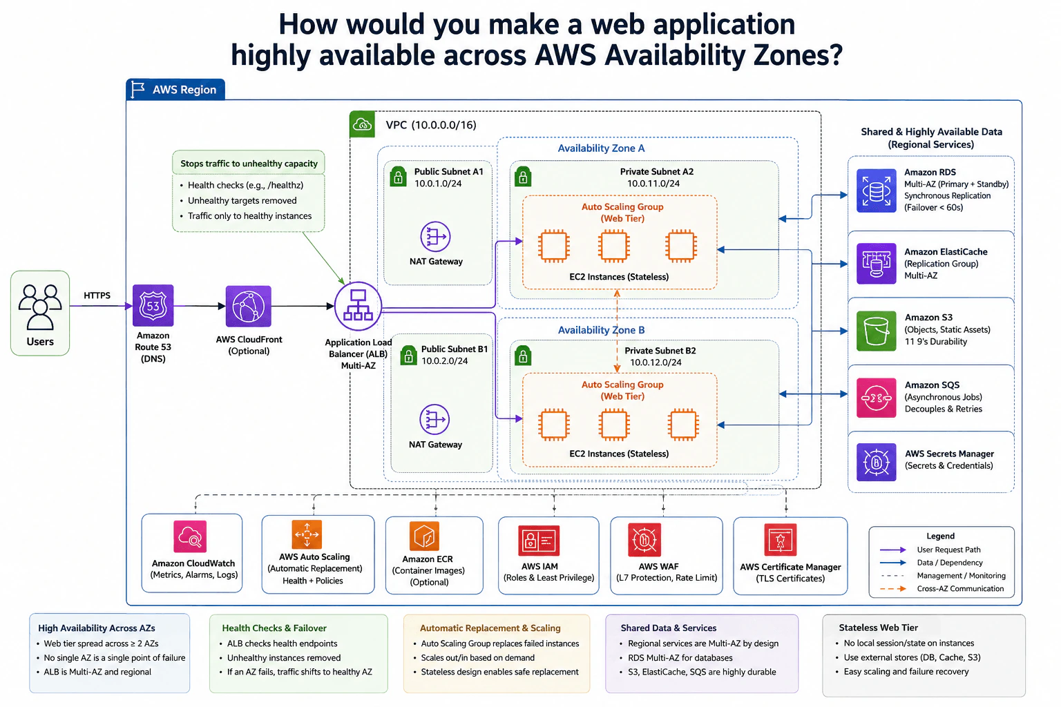
The goal is to keep the web application available when part of one AWS Region fails. An Availability Zone can lose its compute or network capacity, but users should still reach the application through another zone. The diagram handles this by spreading stateless web servers across two Availability Zones. A load balancer checks server health and stops using unhealthy targets. Auto Scaling replaces failed servers. Shared application data is kept outside those EC2 instances. I would explain the normal request path first, then shared data, and finally failure recovery.

Useful Questions to Ask the Interviewer
  1. How quickly should the application recover from an Availability Zone failure?
  2. Does the current web tier store user sessions or files locally?
  3. Which shared data services are required by the application?
  4. Should CloudFront be used in front of the load balancer?
How would you make a web application highly available across AWS Availability Zones? diagram
How to Explain It in an Interview
1. Spread the web tier across two Availability Zones

I would start by removing the Availability Zone as a single failure point. The VPC spans Availability Zone A and Availability Zone B. Each zone has a public subnet and a private subnet. The stateless EC2 web instances run in the private subnets. Each zone also has a NAT Gateway in its public subnet for outbound access from private resources.

2. Follow the normal request path

Users send HTTPS requests through Amazon Route 53. The diagram optionally places AWS CloudFront before the Application Load Balancer. The Application Load Balancer is multi-AZ and sends requests to healthy EC2 targets. The web instances are stateless, which means important user or application state is not stored only on one server. This allows any healthy instance to handle a request.

3. Remove unhealthy capacity automatically

The Application Load Balancer checks a health endpoint such as /healthz. If an EC2 instance fails the health checks, that target is marked unhealthy. The load balancer stops sending new requests to it. Traffic continues to healthy instances. AWS Auto Scaling manages health and replacement policies. It launches replacement capacity when an instance fails. Once a replacement is healthy, it can receive traffic again. If one entire zone fails, healthy targets in the other zone can continue serving requests.

4. Keep shared data outside the web servers

The web tier stays stateless because shared data uses separate services. Amazon RDS is shown as Multi-AZ with a primary and standby. Amazon ElastiCache is shown as a Multi-AZ replication group. Amazon S3 stores objects and static files. Amazon SQS stores background jobs. AWS Secrets Manager stores secrets and credentials. A failed EC2 instance can therefore be replaced without losing the application's shared state.

5. Add operational and security controls

Amazon CloudWatch provides metrics, alarms, and logs. AWS IAM provides roles and least-privilege access. AWS WAF is shown for layer-seven protection and rate limiting. AWS Certificate Manager provides TLS certificates. Amazon ECR is an optional source for container images. These controls support the application without putting important state on one web server.

The main trade-off is cost and operational work. Multi-AZ capacity, separate NAT Gateways, redundant data services, health checks, monitoring, and replacement policies cost more than a simple single-zone design. We accept that extra work because one server or one Availability Zone should not stop the whole application.

Practical Complexity & Trade-offs

The benefit is better availability. A failed EC2 instance can be removed from traffic and replaced automatically. If one Availability Zone fails, healthy instances in the other zone can continue serving users. Keeping the web tier stateless also makes scaling and replacement easier. The downside is higher cost and more setup. We run resources across multiple zones and use shared services such as RDS Multi-AZ, ElastiCache, S3, and SQS. Separate NAT Gateways also add cost. Health checks, monitoring, security rules, and Auto Scaling policies must be configured correctly. This design is more complex than using one zone, but it avoids important single points of failure.

Why Interviewers Ask This

Interviewers ask this to see whether you understand cloud failure boundaries and practical high availability. They want to know if you can spread compute across Availability Zones, keep web servers stateless, use load-balancer health checks correctly, and replace failed capacity automatically. They also want to see whether you protect shared data, avoid single points of failure, and explain the extra cost and complexity clearly.

Interviewer may ask next
What would change if the application currently stores user sessions on the local EC2 instances?

I would keep the same multi-AZ architecture, but I would move session state away from the individual EC2 instances. Local session state makes a user depend on one specific server. If that server fails or Auto Scaling replaces it, another healthy server may not have the user's session.

The diagram already shows Amazon ElastiCache as a shared Multi-AZ service. If it fits the application's session needs, I would store session data there instead of only in local memory or local files. The EC2 web tier would then remain stateless. Any healthy instance behind the Application Load Balancer could handle the user's next request.

This change also makes scaling easier because instances can be added or removed without moving local session data. The downside is that session handling now depends on the shared cache. That service must therefore be sized, monitored, and configured for Multi-AZ availability.

What happens if an entire Availability Zone becomes unavailable?

The design already prepares for that failure by running the stateless web tier in two Availability Zones. If one zone becomes unavailable, the Application Load Balancer stops using unhealthy targets from that zone. New requests can continue going to healthy EC2 instances in the remaining zone.

AWS Auto Scaling continues managing the available capacity. Because the web servers are stateless, users are not tied to the failed instances. Shared dependencies are also outside the local web servers. The diagram shows RDS Multi-AZ, ElastiCache Multi-AZ, Amazon S3, Amazon SQS, and AWS Secrets Manager for shared application needs.

Amazon CloudWatch metrics and alarms help operators see the failure and reduced capacity. The remaining zone still needs enough healthy capacity for the incoming traffic. The main downside is that available compute capacity is temporarily lower. Keeping enough spare capacity for a zone failure also increases normal operating cost.

16. How would you expose an Azure platform service privately to a virtual network?Cloud InfrastructureMedium

Question Details

A workload in a private subnet must reach a managed Azure service without traversing the public internet. Design the private endpoint, subnet and network-policy choices, private DNS resolution, authorization, and validation that the public endpoint is not used.

Short Interview Answer (30-60 seconds)

At a high level, the goal is to let a private workload reach Azure Storage without using the public internet. The main challenge is making the normal Storage name resolve to a private IP and blocking any public fallback. I would explain the design through DNS resolution, the Private Endpoint traffic path, and authorization. Private DNS returns 10.0.2.5, HTTPS goes through Private Link, and Microsoft Entra ID with data-plane RBAC controls access. The trade-off is extra DNS and subnet configuration.

Detailed Explanation

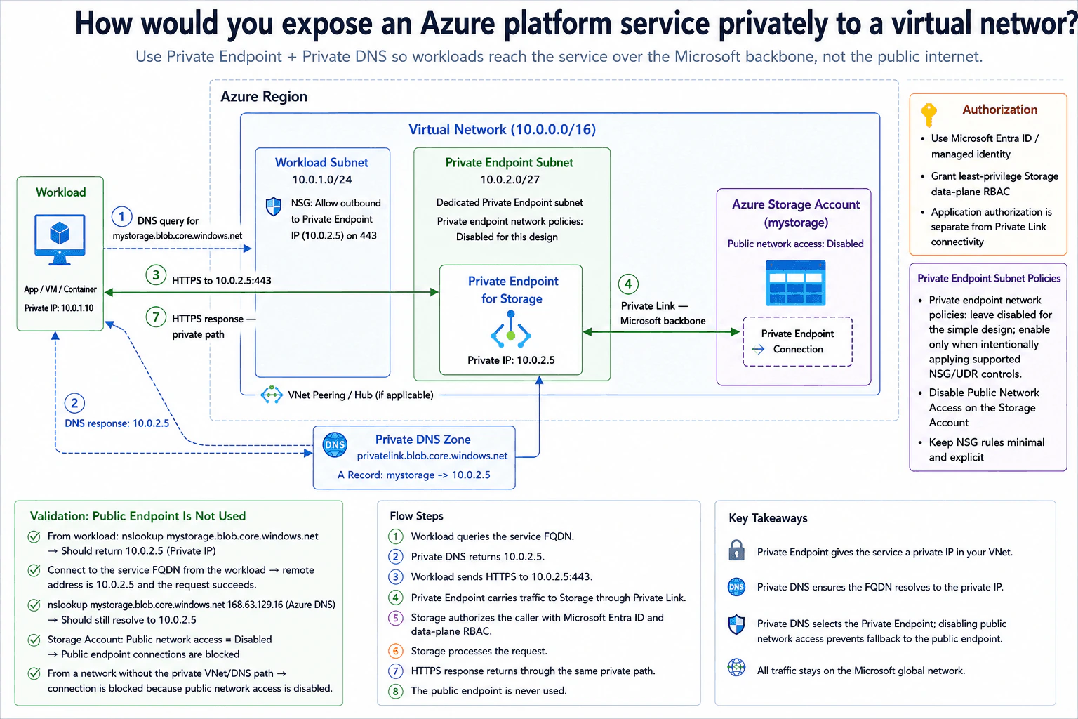
The goal is to let a workload inside a private subnet use an Azure Storage Account without sending traffic through the public internet. The hard part is making the normal Storage service name lead to a private address instead of the public endpoint. We also need to control what the workload can do after it connects. Finally, we need tests that prove the private path is really being used. The diagram solves these needs with Private DNS, a Private Endpoint, Private Link, Microsoft Entra ID, data-plane RBAC, and disabled public network access.

Useful Questions to Ask the Interviewer
  1. Should public network access on the Azure Storage Account be completely disabled?
  2. Will workloads from peered VNets or a hub also need this private path?
  3. Should the workload subnet restrict outbound traffic to the Private Endpoint on port 443?
How would you expose an Azure platform service privately to a virtual network? diagram
How to Explain It in an Interview
1. Start with private DNS

I would start with DNS because the application should keep using the normal Storage FQDN. The workload queries mystorage.blob.core.windows.net. The Private DNS Zone is privatelink.blob.core.windows.net, and its record maps mystorage to 10.0.2.5.

The workload receives 10.0.2.5 as the private destination. That IP belongs to the Private Endpoint inside the VNet. This makes the application choose the private path instead of a public address.

2. Send HTTPS to the Private Endpoint

Next, the workload sends HTTPS traffic to 10.0.2.5:443. The workload is in subnet 10.0.1.0/24. The Private Endpoint is in the dedicated 10.0.2.0/27 subnet.

The workload subnet allows outbound traffic to the Private Endpoint on port 443. For this design, private endpoint network policies are disabled on the Private Endpoint subnet. They can be enabled when supported NSG or route controls are intentionally required.

3. Reach Storage through Private Link

The Private Endpoint carries the request to the Azure Storage Account through Private Link. This keeps the service traffic on the Microsoft network instead of sending it over the public internet. The Storage Account has Public network access: Disabled.

Both controls matter. Private DNS selects the Private Endpoint address. Disabling public network access prevents a public endpoint from becoming a fallback path.

4. Authorize the workload

Private networking decides how the workload reaches Storage. It does not decide what the workload may do. The Storage Account separately authorizes the caller using Microsoft Entra ID and Storage data-plane RBAC.

A managed identity can represent the workload. I would give it only the Storage permissions it needs. After Storage processes the request, the HTTPS response returns through the same private path.

5. Validate the private path

Finally, I would prove the design works. From the workload, nslookup mystorage.blob.core.windows.net should return 10.0.2.5. A lookup using Azure DNS at 168.63.129.16 should also return the private address from inside the VNet.

I would connect to the normal service FQDN and confirm the connection uses 10.0.2.5. The request should succeed. Then I would test from a network without the private VNet and DNS path. That connection should be blocked because public network access is disabled.

Practical Complexity & Trade-offs

The benefit is that the workload keeps using the normal Storage name while its traffic goes to a private IP. Public network access can stay disabled, so there is no public fallback path. Network access and application permissions are also handled separately. The downside is more setup. Private DNS must resolve correctly, the Private Endpoint needs the right subnet configuration, and the workload must be allowed to reach port 443. If peered VNets or a hub need access, their routing and DNS path must also work. A DNS mistake can stop access even when Storage and the Private Endpoint are healthy.

Why Interviewers Ask This

The interviewer wants to see whether you understand that private cloud access needs several pieces working together. Creating a Private Endpoint alone is not enough. You need correct DNS, subnet choices, authorization, and public access controls. They also want to see whether you can prove which network path an application uses instead of simply assuming the design is private.

Interviewer may ask next
How would the design change if workloads in a peered VNet or hub network also needed to reach the same Storage Account privately?

I would keep the same Storage Account and Private Endpoint. The main change would be extending network reachability and private DNS resolution to the additional workload network.

The diagram already shows VNet peering or a hub as an optional path. The new workload must be able to reach the Private Endpoint address, 10.0.2.5, through that network connection. Its DNS setup must also use the Private DNS Zone for privatelink.blob.core.windows.net. When it looks up mystorage.blob.core.windows.net, it should still receive 10.0.2.5.

I would then check the workload-side NSG and routes. HTTPS traffic must be able to reach the Private Endpoint on port 443. The Storage Account would still authorize the caller with Microsoft Entra ID and data-plane RBAC. Public network access would remain disabled.

The downside is extra DNS and routing work across networks. VNet peering alone does not guarantee that private name resolution is configured correctly.

How would you prove during troubleshooting that an application is not accidentally using the Storage Account public endpoint?

I would check DNS first, then verify the real connection path. From the workload, I would run nslookup mystorage.blob.core.windows.net. The result should be the Private Endpoint address, 10.0.2.5.

I would also query Azure DNS at 168.63.129.16 from inside the VNet. The Storage FQDN should still lead to 10.0.2.5. Next, I would connect to the normal service FQDN and confirm the connection uses that private address. The HTTPS request should succeed through the Private Endpoint and Private Link.

I would also verify that the Storage Account shows Public network access: Disabled. Finally, I would try the service from a network that does not have the private VNet and DNS path. That connection should be blocked.

The main lesson is that DNS alone is not enough proof. I want both correct name resolution and a successful private connection, plus a failed public-path test.

17. How would you combine AWS Elastic Load Balancing and Auto Scaling for variable traffic?Cloud InfrastructureMedium

Question Details

Design the request path and scaling loop for a stateless service whose demand rises and falls throughout the day. Define target registration and health, scaling signals, warm-up behavior, minimum and maximum capacity, connection draining, and protection against rapid scale oscillation.

Short Interview Answer (30-60 seconds)

At a high level, I would use the Application Load Balancer to spread changing traffic across healthy stateless EC2 instances. The main challenge is scaling capacity without reacting too aggressively to short traffic changes. I would explain the request path, target health, and the Auto Scaling feedback loop. CloudWatch metrics drive target tracking. New instances warm up before influencing scaling. Scale-in uses connection draining. Minimum and maximum capacity, warm-up, cooldown behavior, and target-tracking safeguards reduce rapid scaling changes.

Detailed Explanation

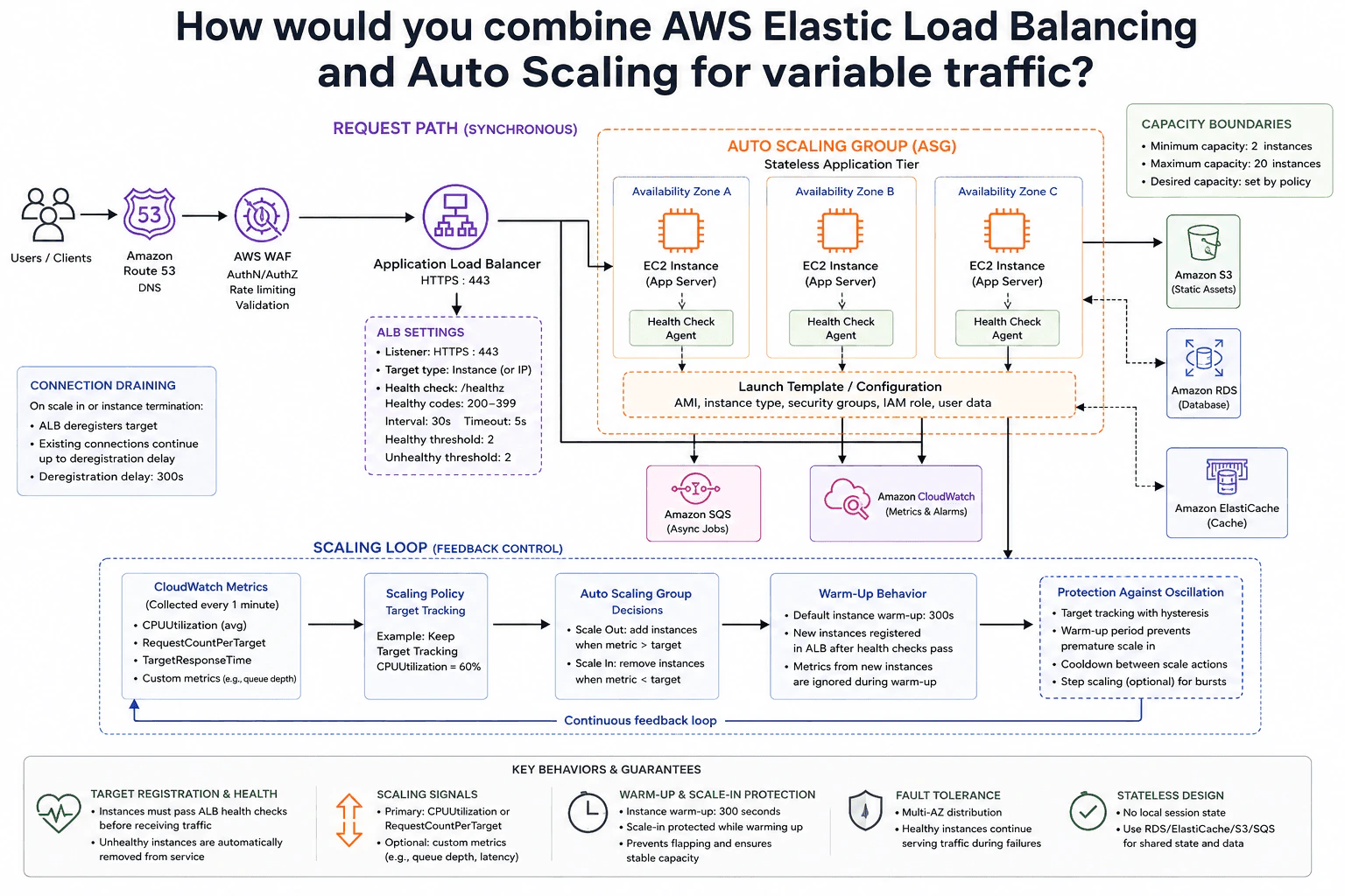
The goal is to keep a stateless application responsive while traffic rises and falls during the day. The hard part is matching capacity to demand without adding and removing instances too quickly. The diagram handles this with two connected flows. The request path sends traffic through an Application Load Balancer to healthy EC2 instances. The scaling loop watches CloudWatch metrics and changes the Auto Scaling Group. Health checks, warm-up time, capacity limits, and connection draining make those changes safer.

Useful Questions to Ask the Interviewer
  1. Which metric should be the main scaling signal, such as CPU or requests per target?
  2. How quickly can traffic increase during the busiest period?
  3. What minimum and maximum capacity should we allow?
  4. How long does a new instance normally need before it is ready?
How would you combine AWS Elastic Load Balancing and Auto Scaling for variable traffic? diagram
How to Explain It in an Interview
1. Explain the normal request path

I would start with how a normal request reaches the application. Users resolve the service through Amazon Route 53. Traffic then passes through AWS WAF and reaches the Application Load Balancer over HTTPS on port 443.

The diagram places authentication, authorization, rate limiting, and validation near AWS WAF. In practice, WAF handles web filtering and rate limiting, while application authentication and authorization normally need a separate identity or application control. The ALB then sends the request to a healthy registered target.

2. Register and route only healthy targets

The service runs on EC2 application servers across three Availability Zones. Each server is stateless, so a request can go to any healthy instance. The application returns its response through the ALB to the client.

The diagram shows a health check using /health. Healthy HTTP codes are 200 through 399. The interval is 30 seconds, the timeout is 5 seconds, and both healthy and unhealthy thresholds are two checks. A new target receives traffic only after it passes health checks. An unhealthy target is removed from service.

3. Drive scaling from CloudWatch metrics

Amazon CloudWatch provides the feedback signals. The diagram shows average CPU utilization, RequestCountPerTarget, TargetResponseTime, and custom metrics such as queue depth.

A target tracking policy compares the selected metric with a target value. The example keeps average CPU near 60%. When demand stays above the target, the Auto Scaling Group adds instances. When demand falls, it can remove instances. Desired capacity always stays between the configured minimum and maximum.

4. Control capacity and instance warm-up

The Auto Scaling Group uses a Launch Template or configuration containing the AMI, instance type, security groups, IAM role, and user data. The diagram sets minimum capacity to two instances and maximum capacity to twenty.

New instances use a 300-second warm-up period. They register with the ALB after health checks pass. Their metrics are ignored during warm-up. This prevents a new instance from causing another scaling decision before it has settled.

5. Make scale-in safe and avoid rapid oscillation

During scale-in, the ALB deregisters the target before termination. Existing connections can continue during the 300-second deregistration delay. This connection-draining period gives active requests time to finish.

Target tracking, warm-up behavior, cooldown between scale actions, and scale-in protection reduce rapid up-and-down scaling. Step scaling is shown as an optional choice for bursts. Because the service is stateless, shared data stays outside the EC2 instances. The diagram shows Amazon RDS, Amazon ElastiCache, Amazon S3, and Amazon SQS for shared data, caching, static assets, and asynchronous jobs.

Practical Complexity & Trade-offs

The benefit is that capacity follows traffic instead of staying fixed all day. The ALB also keeps requests away from unhealthy targets. Health checks and warm-up stop new instances from receiving traffic too early. The downside is that scaling is not instant. A new EC2 instance needs time to start and become healthy. Connection draining also makes scale-in slower because active requests should finish first. Cooldown behavior and target tracking reduce rapid scaling changes, but they can delay the next adjustment. Minimum capacity costs money during quiet periods, while maximum capacity prevents the group from growing without a limit.

Why Interviewers Ask This

Interviewers ask this to see whether you understand the difference between distributing traffic and changing capacity. They want to know whether you can choose useful scaling signals, register only healthy targets, handle warm-up correctly, and remove capacity safely. A strong answer also shows that you understand minimum and maximum limits, connection draining, and how to avoid rapid scaling changes without claiming that scaling happens instantly.

Interviewer may ask next
What would you change if traffic increased much faster than new EC2 instances could warm up?

I would keep the same ALB and Auto Scaling Group design, but I would make scale-out react earlier to demand. The diagram already shows several possible signals. I could use RequestCountPerTarget or a custom metric such as queue depth instead of waiting only for CPU utilization to rise.

I would also choose a minimum capacity that gives the service some spare room for normal bursts. For a much larger burst, the diagram shows optional step scaling. That can add more instances when the metric moves far beyond its normal target.

The existing warm-up rule should stay. New instances still need to pass ALB health checks before receiving traffic, and their metrics should be ignored during the warm-up period.

The main downside is cost. Keeping extra capacity or scaling out more aggressively means some instances may remain unused during quieter periods.

How would you make scale-in safer when some requests take a long time to finish?

I would keep the same Auto Scaling Group and ALB, but I would tune the connection-draining period around the real request duration. When scale-in removes an instance, the ALB first deregisters that target. It stops receiving new requests while existing connections are allowed to finish.

The diagram uses a 300-second deregistration delay. If valid requests can run longer than that, I would consider increasing the delay. I would also keep the warm-up and scale-in protection shown in the diagram so recently started instances are not removed too quickly.

The target-tracking and cooldown behavior should remain because they help stop repeated scale-out and scale-in decisions around the same demand level.

The downside is slower scale-in. Instances can remain alive while requests drain, so the service may keep extra capacity and cost for a little longer.

18. How would you connect many AWS VPCs and an on-premises network through a central hub?Cloud InfrastructureMedium

Question Details

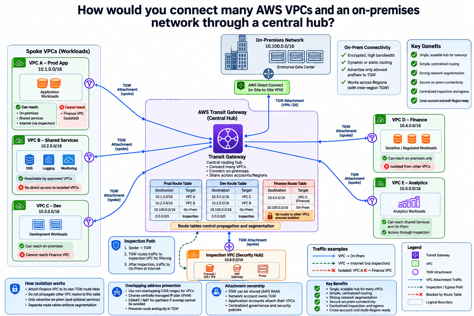
Design a hub-and-spoke network using AWS Transit Gateway. Cover route propagation and segmentation, attachment ownership, overlapping-address prevention, inspection paths, on-premises connectivity, and how one spoke is prevented from reaching another when isolation is required.

Short Interview Answer (30-60 seconds)

At a high level, I would use AWS Transit Gateway as the central hub for the VPCs and the on-premises network. The main challenge is controlling reachability without creating a full mesh. I would explain the design in three parts: attachments, segmented routing, and inspection. Each VPC attaches to the hub, route tables expose only approved networks, and selected traffic passes through the Inspection VPC. The benefit is simpler central control, but routing policies must be managed carefully.

Detailed Explanation

The goal is to connect many separate cloud networks and one on-premises network through a central place. The hard part is deciding which networks should be allowed to communicate. Some workloads need shared services, on-premises systems, or internet access. Other workloads, such as Finance, must stay isolated from other spokes. The diagram solves this by using one central hub, separate spoke connections, controlled routing rules, and an inspection path for selected traffic. This keeps connectivity simple while still giving the network team strong control over who can reach what.

Useful Questions to Ask the Interviewer
  1. Which VPCs should be allowed to communicate with each other?
  2. Which VPCs must remain isolated?
  3. Should on-premises use AWS Direct Connect, Site-to-Site VPN, or both?
  4. Which traffic must pass through the Inspection VPC?
  5. Are the spoke VPCs owned by different AWS accounts?
How would you connect many AWS VPCs and an on-premises network through a central hub? diagram
How to Explain It in an Interview
1. Use AWS Transit Gateway as the central hub

I would start by saying that every spoke connects to AWS Transit Gateway instead of connecting directly to every other VPC. The diagram shows Prod, Shared Services, Dev, Finance, and Analytics as separate spoke VPCs. This avoids a large full-mesh network and gives us one central routing point.

2. Control reachability with segmented route tables

The next part is routing. Transit Gateway route tables decide which destination networks each attachment can reach. I would propagate only the routes that each segment needs. Prod can reach Shared Services and on-premises systems, while Dev can reach on-premises but not Finance. Analytics can reach Shared Services and on-premises. This selective routing prevents the Transit Gateway from becoming an unrestricted full mesh.

3. Isolate sensitive spokes

Finance is placed in its own routing segment. Its route table does not contain routes to other spoke VPCs. Other spokes also do not receive the Finance route. This means sharing the same Transit Gateway does not automatically allow spoke-to-spoke communication. Separate route tables enforce the isolation policy.

4. Connect on-premises and inspect selected traffic

The on-premises network connects through AWS Direct Connect or Site-to-Site VPN, as shown in the diagram. Only approved prefixes should be advertised toward the hub. For sensitive or internet-bound traffic, Transit Gateway routes traffic through the Inspection VPC. That VPC contains firewall and IDS/IPS controls, plus NAT Gateway and proxy functions shown in the diagram. After inspection, traffic continues to its approved destination.

5. Manage ownership and address space carefully

For multiple AWS accounts, the Transit Gateway can be shared with AWS RAM. Application accounts attach their own VPCs while the hub and routing policy stay centrally governed. CIDR ranges should be unique across VPCs and on-premises networks. If overlap with a partner cannot be avoided, the diagram shows NAT or CGNAT as a possible translation boundary. The main trade-off is easier central management in exchange for careful route, ownership, and address planning.

Practical Complexity & Trade-offs

The benefit is that one Transit Gateway replaces many direct VPC connections. This makes the network easier to grow and gives the team one place to control routing. Separate route tables also make isolation easier. The downside is that a routing mistake can allow traffic that should be blocked or stop traffic that should work. Central inspection also adds another path that must be planned and monitored. Address ranges need coordination because overlapping CIDRs can create routing ambiguity. We accept this extra planning because the design gives much better control than a large mesh of separate network connections.

Why Interviewers Ask This

Interviewers ask this to see whether you can design more than basic VPC connectivity. They want to know if you understand central routing, route segmentation, spoke isolation, on-premises connectivity, inspection paths, multi-account ownership, and CIDR planning. They are also testing your judgment. A good answer should explain not only how networks connect, but also how you stop unwanted communication and keep the design manageable as more VPCs are added.

Interviewer may ask next
How would you keep the Finance VPC isolated while still allowing it to reach on-premises systems?

I would keep Finance attached to the same AWS Transit Gateway, but place it in its own routing segment. Its Transit Gateway route table would contain only the approved on-premises routes and any other destinations that Finance is explicitly allowed to use. It would not contain routes to Prod, Dev, Shared Services, or Analytics.

I would also avoid propagating the Finance CIDR into the route tables used by those other spokes. That blocks the reverse direction as well. The important point is that two VPCs can share one Transit Gateway without automatically being able to reach each other.

If Finance traffic needs inspection, I would route that approved path through the Inspection VPC before it continues to on-premises systems. The downside is more routing policy to maintain. Every allowed path must be added deliberately and tested so future route changes do not accidentally weaken the isolation.

What would you do if a partner network has a CIDR range that overlaps one of your VPCs?

I would first avoid the overlap if the address plan can still be changed. The diagram treats unique, non-overlapping CIDRs as the normal design because Transit Gateway needs clear destination routes. I would coordinate VPC and on-premises address ranges before adding new networks.

If a partner network already exists and its addresses cannot be changed, I would place a translation boundary in the path. The diagram shows NAT or CGNAT for this case. That presents translated addresses that do not conflict with the VPC ranges used behind the Transit Gateway.

I would still keep the same hub-and-spoke architecture and expose only the translated, approved prefixes to the relevant routing segment. The downside is added operational complexity. Address translation makes troubleshooting harder because the address seen on one side is different from the original address on the other side.

19. How would you build resilient hybrid connectivity to AWS?Cloud InfrastructureHard

Question Details

An on-premises datacenter needs private, predictable access to several AWS VPCs. Design AWS Direct Connect as the primary path with an encrypted VPN backup, including routing, redundancy at devices and locations, failure detection, route preference, DNS, and failover testing.

Short Interview Answer (30-60 seconds)

At a high level, I would give the datacenter two independent ways to reach AWS. Direct Connect is the normal path because it is private and predictable. Site-to-Site VPN is the encrypted backup. I would explain the design in three parts: redundant Direct Connect, BGP-controlled VPN failover, and shared routing through Transit Gateway to several VPCs. DNS stays unchanged during failover. The main trade-off is extra circuits, routing policy, monitoring, and testing in exchange for better resilience.

Detailed Explanation

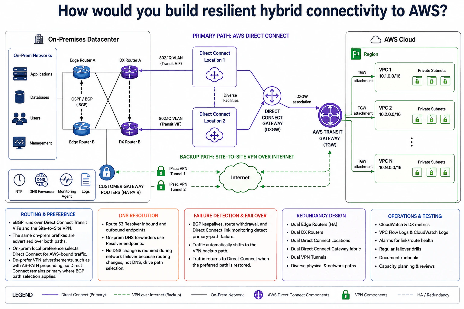
The goal is to let systems in the on-premises datacenter reach several AWS VPCs through a private, predictable primary path and a secure backup path. The hard part is keeping traffic available when a router, circuit, Direct Connect location, or primary route fails. The diagram solves this with two Direct Connect locations, two on-premises router pairs, an AWS Direct Connect Gateway, AWS Transit Gateway, and a Site-to-Site VPN backup. BGP chooses the preferred route. DNS stays the same during failover. Regular monitoring and planned failover drills prove the design works.

Useful Questions to Ask the Interviewer
  1. How many VPCs and AWS Regions must be reached?
  2. What failover time is acceptable?
  3. Which on-premises and VPC prefixes must be exchanged?
  4. What traffic volume must the VPN carry during a Direct Connect outage?
  5. How often can we run planned failover tests?
How would you build resilient hybrid connectivity to AWS? diagram
How to Explain It in an Interview
1. Build redundancy inside the datacenter

I would start by removing single device failures on premises. The diagram has Edge Router A and B, plus DX Router A and B. Their cross-connected layout gives more than one path through the datacenter.

OSPF and BGP handle internal routing between these routers. The Customer Gateway Routers form an HA pair for the backup VPN path. NTP, the DNS Forwarder, the Monitoring Agent, and Logs support daily operations.

2. Make Direct Connect the normal path

Normal traffic uses AWS Direct Connect. The design has Direct Connect Location 1 and Location 2, giving location diversity.

Each connection uses an 802.1Q Transit VIF. A Transit VIF is the Direct Connect virtual interface used to reach Transit Gateway through a Direct Connect Gateway. Both Direct Connect locations feed the same Direct Connect Gateway. That gateway has a DXGW association to AWS Transit Gateway.

3. Use Transit Gateway as the AWS routing hub

AWS Transit Gateway is the central AWS routing point. VPC 1, VPC 2, and the other VPCs connect through separate TGW attachments.

This keeps the hybrid design simple as more VPCs are added. The datacenter does not need a separate Direct Connect design for every VPC.

4. Keep Site-to-Site VPN ready as backup

The backup path is an encrypted Site-to-Site VPN over the Internet. The diagram shows two parallel IPsec VPN tunnels from the Customer Gateway Routers to AWS Transit Gateway.

BGP runs over both the Direct Connect Transit VIFs and the VPN. On-premises local preference makes Direct Connect the first choice for AWS-bound traffic. For AWS-to-on-premises traffic, VPN advertisements can be made less attractive with AS-PATH prepending where BGP path selection applies.

5. Detect failure, keep DNS stable, and test recovery

BGP keepalives, route withdrawal, and Direct Connect link monitoring detect primary-path failure. If Direct Connect routes disappear, traffic moves to the VPN. When the preferred Direct Connect path returns, traffic moves back.

Route 53 Resolver inbound and outbound endpoints support hybrid DNS. On-premises DNS forwarders use those Resolver endpoints. Failover changes routing, not DNS, so applications do not need a DNS change.

CloudWatch and Direct Connect metrics, VPC Flow Logs, CloudWatch Logs, alarms, and on-premises monitoring help operators see failures. I would run regular failover drills, verify application and DNS access, and document the runbook. The trade-off is more cost and operational work for much stronger resilience.

Practical Complexity & Trade-offs

The benefit is that a single router, circuit, or Direct Connect location failure does not have to disconnect the datacenter from AWS. Two Direct Connect locations protect the main path, while two VPN tunnels provide an encrypted backup. Transit Gateway also gives several VPCs one shared AWS routing hub. The downside is more cost and more network work. The team must manage several routers, BGP policies, Direct Connect links, VPN tunnels, alarms, and tests. A bad routing policy could send traffic over the backup path unexpectedly. We accept this added complexity because it gives the network more ways to survive failures.

Why Interviewers Ask This

Interviewers ask this to see whether you can design for real network failures instead of drawing one happy path. They want to test your understanding of redundancy, BGP route preference, encrypted backup connectivity, DNS, monitoring, and failover testing. They also want to see whether you can explain why Direct Connect stays primary and how traffic safely moves to VPN when that path fails.

Interviewer may ask next
What would happen if one entire Direct Connect location failed during business hours?

I would keep the same basic design because it already has two diverse Direct Connect locations. When one location fails, BGP routes learned through that path are withdrawn. The second Direct Connect location can continue carrying traffic if it is healthy.

The remaining Direct Connect route should still be preferred over the Site-to-Site VPN. On the on-premises side, local preference keeps Direct Connect preferred for AWS-bound traffic. For traffic coming from AWS, the VPN path remains less attractive through the BGP policy shown in the design.

CloudWatch and Direct Connect metrics should raise an alarm for the failed path. I would also check VPC Flow Logs, route health, and application access.

If both Direct Connect paths fail, the two IPsec VPN tunnels provide the backup route through AWS Transit Gateway. The downside is that the Internet-based VPN path may be less predictable than Direct Connect.

How would you prove that the VPN backup really works before a real Direct Connect outage?

I would run a planned failover drill using the same architecture. During a controlled maintenance window, I would remove or disable the preferred Direct Connect path. Then I would watch BGP withdraw those routes and confirm that traffic moves to the Site-to-Site VPN.

I would test application access from the datacenter to VPC 1, VPC 2, and the other TGW attachments. I would also test DNS through the Route 53 Resolver endpoints. DNS should keep working because failover changes the network route, not the DNS design.

During the drill, I would watch CloudWatch, Direct Connect metrics, VPC Flow Logs, CloudWatch Logs, alarms, and on-premises monitoring. After restoring Direct Connect, I would confirm that traffic returns to the preferred path.

The downside is that realistic failover tests can affect live traffic, so they need a documented runbook and careful scheduling.

20. How would you design an Azure enterprise landing zone?Cloud InfrastructureHard

Question Details

Create a foundation for multiple subscriptions and teams. Include management-group hierarchy, subscription boundaries, centralized identity, policy assignment, network topology, shared services, logging, security operations, cost ownership, and a controlled path for teams to provision resources.

Short Interview Answer (30-60 seconds)

At a high level, the goal is to give many Azure teams a safe foundation without slowing them down. The main challenge is balancing central control with team self-service. I would explain the design in three parts: identity and governance, subscription and network boundaries, then operations and provisioning. Management groups apply common guardrails, hub-and-spoke networking centralizes connectivity, and shared monitoring, security, and cost controls cover every workload. Teams provision through an automated path. The trade-off is more shared-platform dependency.

Detailed Explanation

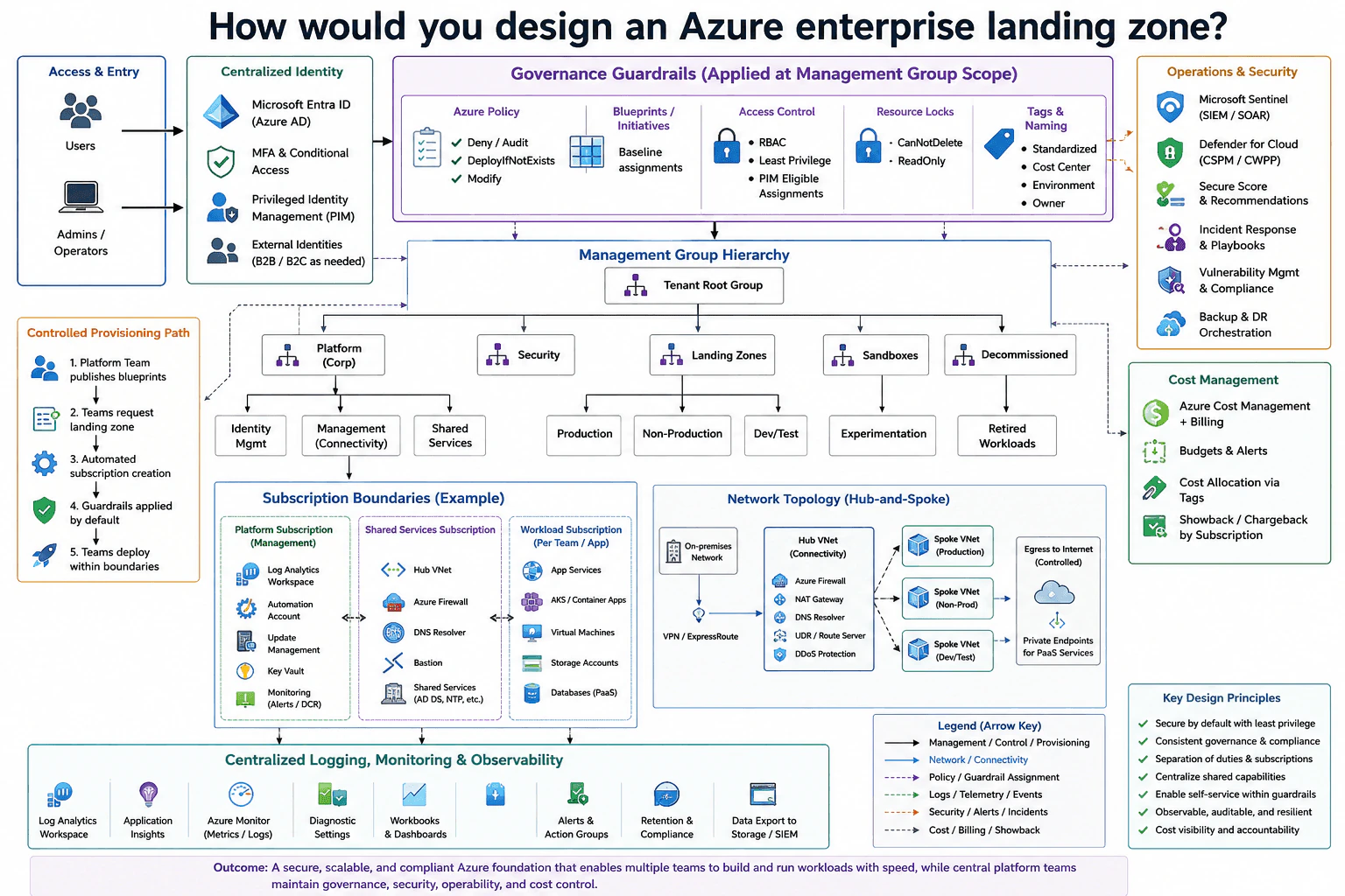
The goal is to give many teams a common Azure foundation where they can build safely without creating a different setup for every project. The difficult part is balancing team freedom with company-wide control. Identity, security, networking, monitoring, and cost ownership must stay consistent across many subscriptions. The diagram solves this by putting shared rules above the subscriptions, separating platform services from workloads, centralizing important operations, and giving teams a controlled path to request and deploy resources.

Useful Questions to Ask the Interviewer
  1. How much freedom should each application team have?
  2. Should production and non-production always use separate subscriptions?
  3. Which shared services must the central platform team operate?
  4. Do workloads need private connectivity to on-premises systems?
  5. How should costs be divided between teams and applications?
How would you design an Azure enterprise landing zone? diagram
How to Explain It in an Interview
1. Start with centralized identity and governance

I would start with Microsoft Entra ID, shown as Azure AD in the diagram. Users and administrators authenticate through this central identity system. MFA and Conditional Access add stronger sign-in checks. Privileged Identity Management, or PIM, gives administrators temporary privileged access. External identities support B2B or B2C access when needed.

Above the subscriptions, Azure Policy provides common guardrails. The diagram shows deny, audit, DeployIfNotExists, and modify policies. It also shows baseline initiatives, RBAC with least privilege, PIM-eligible assignments, resource locks, naming rules, and tags for owner, environment, and cost center.

2. Organize subscriptions with management groups

The Tenant Root Group sits at the top. Under it, the design separates Platform, Security, Landing Zones, Sandboxes, and Decommissioned areas.

Platform contains Identity Management, Management or Connectivity, and Shared Services. Landing Zones contain Production, Non-Production, and Dev/Test. Sandboxes contain experimentation. Decommissioned contains retired workloads. This structure gives each subscription a clear purpose while allowing common policies to be applied to groups of subscriptions.

3. Separate shared services from workload subscriptions

The Platform Subscription for management contains Log Analytics Workspace, Automation Account, Update Management, Key Vault, and monitoring. The Shared Services Subscription contains the Hub VNet, Azure Firewall, DNS Resolver, Bastion, and shared infrastructure such as directory, DNS, and NTP services.

Each team or application gets a Workload Subscription. It may contain App Services, AKS or Container Apps, virtual machines, storage accounts, and managed databases. This creates clear ownership and limits how one workload can affect another.

4. Use a hub-and-spoke network

The Hub VNet provides central connectivity. It contains Azure Firewall, NAT Gateway, DNS Resolver, user-defined routing, and DDoS Protection. Production, Non-Production, and Dev/Test use separate Spoke VNets.

The hub connects to on-premises networks through VPN or ExpressRoute. Internet egress follows the controlled central path. Private Endpoints give workloads private access to supported Azure platform services.

5. Centralize operations, security, cost, and provisioning

Diagnostic Settings feed centralized observability. The diagram includes Log Analytics, Application Insights, Azure Monitor, Workbooks, Alerts and Action Groups, retention and compliance, and data export to storage or a SIEM.

Microsoft Sentinel supports SIEM and SOAR security operations. Defender for Cloud adds security posture and workload protection. Secure Score, recommendations, vulnerability management, compliance, incident-response playbooks, and backup or disaster-recovery orchestration support the operations team.

Cost Management and Billing provides budgets, alerts, tag-based cost allocation, and showback or chargeback by subscription.

For provisioning, the Platform Team publishes approved blueprints. Teams request a landing zone. Automation creates the subscription, applies the required guardrails, and then teams deploy resources inside those boundaries.

Practical Complexity & Trade-offs

The benefit is that teams get the same security, networking, monitoring, and cost controls without rebuilding them for every project. Management groups also make common rules easier to apply across many subscriptions. The downside is that shared services become important dependencies. A problem in central networking, identity, or monitoring can affect several teams. Hub-and-spoke networking also adds routing and firewall work. Strong policies may slow a team when it needs an exception. Cost tags and ownership rules need discipline. We accept these costs because the design gives teams useful self-service while keeping company-wide control and visibility.

Why Interviewers Ask This

Interviewers ask this question to see whether you can organize a large Azure environment, not just deploy individual resources. They want to test how you separate central responsibilities from team ownership. They also look for good judgment around identity, governance, subscription boundaries, networking, shared services, monitoring, security operations, cost ownership, and automation. A strong answer shows that you can give teams freedom without losing control.

Interviewer may ask next
How would you change this landing zone if teams need much more self-service and should not wait for the platform team for normal deployments?

I would keep the same management-group, identity, subscription, network, monitoring, and security structure. I would change the controlled provisioning path so more approved work can happen automatically.

The Platform Team would still publish the approved blueprints and baseline rules. Teams would request a landing zone through the same controlled process. Automation would create the subscription and apply the required Azure Policy assignments, RBAC, tags, networking settings, monitoring settings, and cost controls.

After that, teams could deploy approved resources directly inside their Workload Subscriptions. Production, Non-Production, and Dev/Test would still remain separate. Shared connectivity would still use the Hub VNet. Central logging, Sentinel, Defender for Cloud, and Cost Management would continue to cover those subscriptions.

The downside is that the automation becomes more important. A bad blueprint, policy, or provisioning change could affect many teams. The platform team therefore needs careful review and testing of those shared definitions.

What would you do if a workload must privately reach an on-premises system and should avoid normal public internet paths?

I would keep the workload inside its existing Spoke VNet and use the central connectivity path already shown in the diagram. Traffic would move from the spoke into the Hub VNet and then reach the on-premises network through VPN or ExpressRoute.

The central connectivity team would continue to manage Azure Firewall, DNS Resolver, user-defined routing, NAT Gateway, and the hub connection. This avoids giving every workload team its own separate connection to the corporate network.

For supported Azure platform services, the workload could use Private Endpoints. These provide private network access to those services instead of relying on their normal public endpoint.

The same Diagnostic Settings, Log Analytics, Azure Monitor, Sentinel, and Defender for Cloud controls would remain in place so operations and security teams keep visibility.

The downside is greater dependence on the Hub VNet. A routing, firewall, DNS, VPN, or ExpressRoute problem can affect several connected workloads.

More questions load as you scroll

Disclaimer: This interview guide is for educational and informational purposes only. It is designed to help readers prepare, but it does not guarantee any interview result, hiring decision, offer, or outcome. Interview questions, hiring criteria, and preferred answers can vary by employer, interviewer, industry, location, and time. The examples and explanations reflect the authors' research and judgment, are provided without warranties of any kind, and should not be treated as the only correct approach. Diagrams are simplified illustrations intended to highlight the main components and their interactions; actual systems and implementations may be more complex. Alternative approaches may be equally valid or better suited to a particular question, context, or interviewer. To the fullest extent permitted by applicable law, the author, contributors, and publisher are not liable for decisions made, actions taken, or losses incurred based on this guide.

Content Accuracy and Verification: To the fullest extent permitted by applicable law, we do not represent or warrant that interview guides, questions, answers, examples, or diagrams are accurate, complete, current, error-free, or suitable for any particular purpose. You are responsible for independently reviewing and verifying the information before relying on it.